Close
0%
0%

Portable Sound Visualization AR Device

A portable AR device that superimposes an image showing the location of a sound source on an image captured by a camera.

Similar projects worth following
This device is a very simple portable AR device that allows people who are completely deaf or have difficulty localizing the direction of sound due to hearing impairment in one ear to visually perceive the presence of sound and the position of the sound source.

The microphone array attached to the front of the device is equipped with seven MEMS microphones, which estimate the direction of the sound source by utilizing the slight time difference it takes for the sound to reach each microphone.

By converting the direction of the sound source into a color map and combining it with the image captured by an image sensor, the device generates a real-time AR image that displays the position of the sound source in the real world on the display located on the back of the device.

The device is made by combining commercially available boards and development boards and can be relatively easily assembled even by those without specialized knowledge.

Overview:

Microphone arrays that use multiple microphones are widely used, for example, in smart speakers to detect the direction of the speaker. In recent years, inexpensive microphone array boards that incorporate MEMS microphones onto PCBs have also been released. The device we created combines a commercial microphone array with a high-performance microcontroller, and is an AR device that can display real-time estimated sound source positions on video images.

The mechanism for estimating the sound source location:

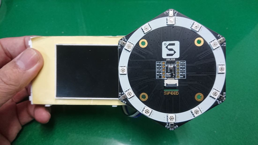
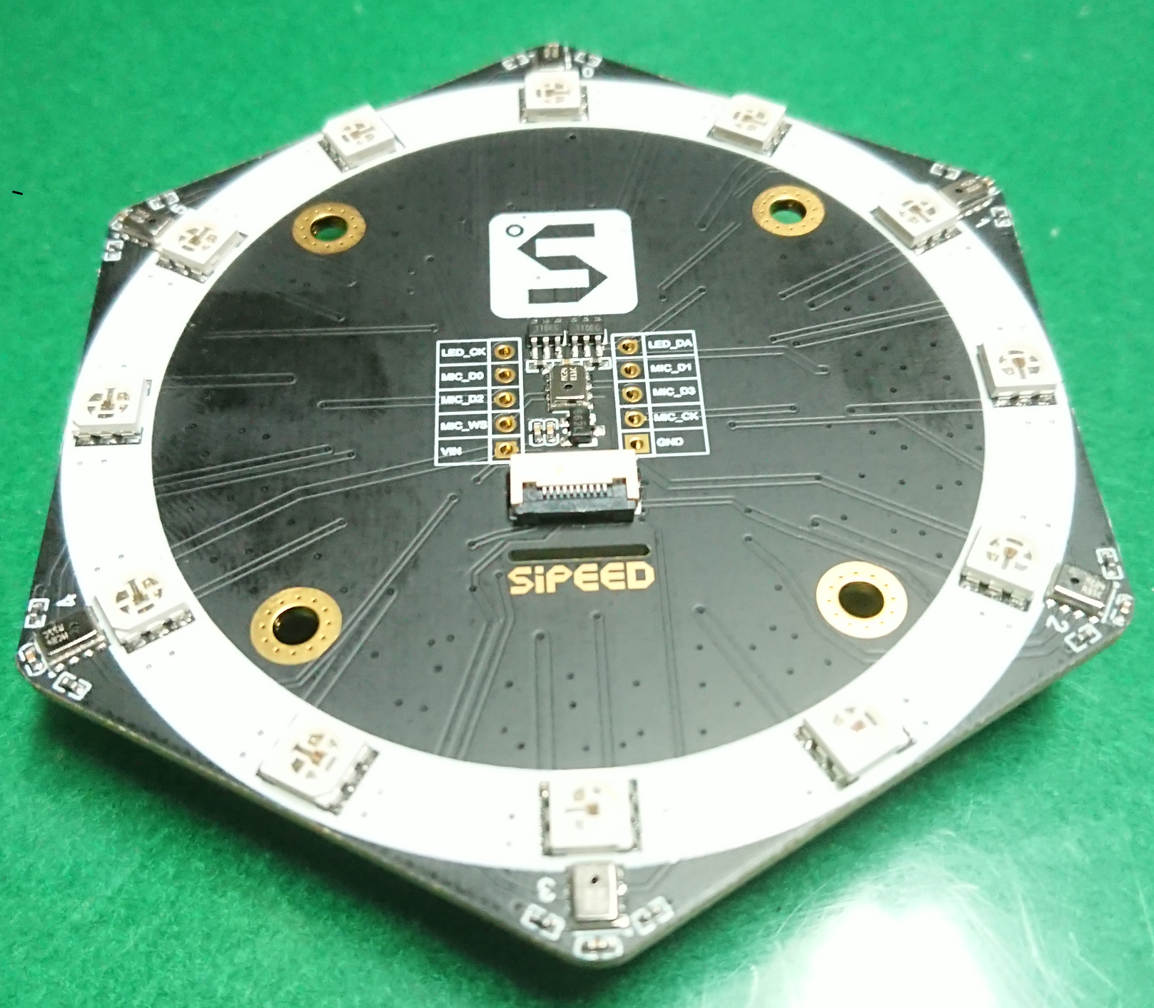
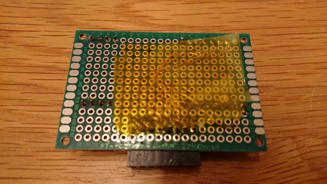
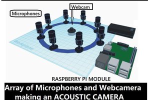
Microphone arrays are geometrically arranged on a plane. Sounds emitted from the source propagate through the air and reach the microphone array. 

When the sound reaches the microphone array vertically to the PCB where the microphone array is mounted, the timing for the sound wave to reach each microphone is almost the same. On the other hand, when the sound wave arrives from a direction with a certain tilt angle relative to the microphone array, there is a time difference between when each microphone detects the sound. 

By detecting and analyzing this time difference, it is possible to estimate from which direction the sound came.

Functions:

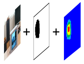
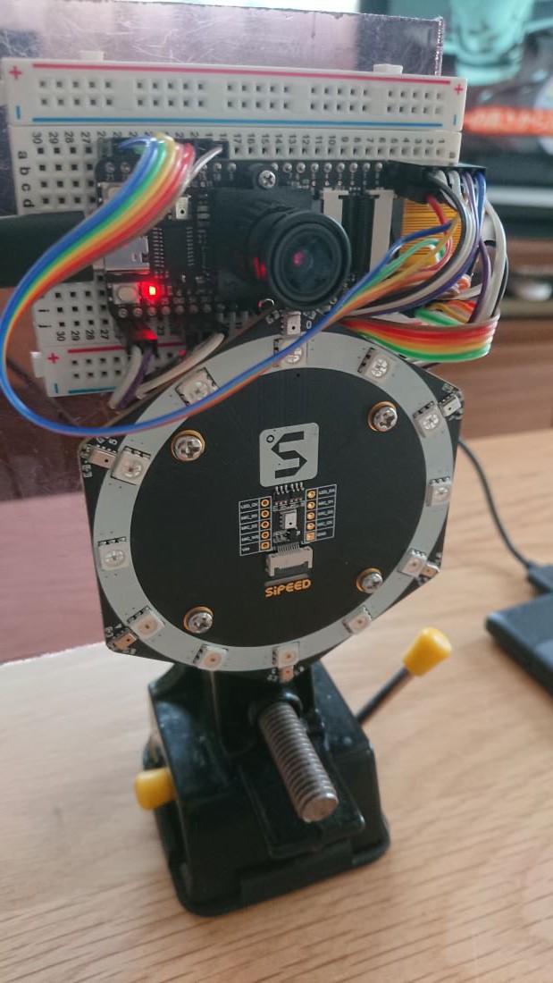
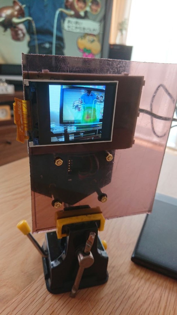
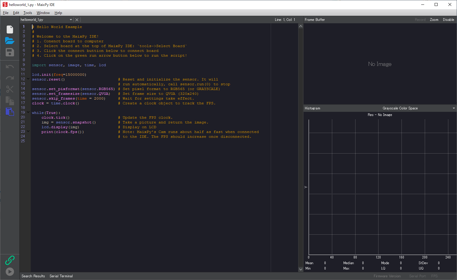
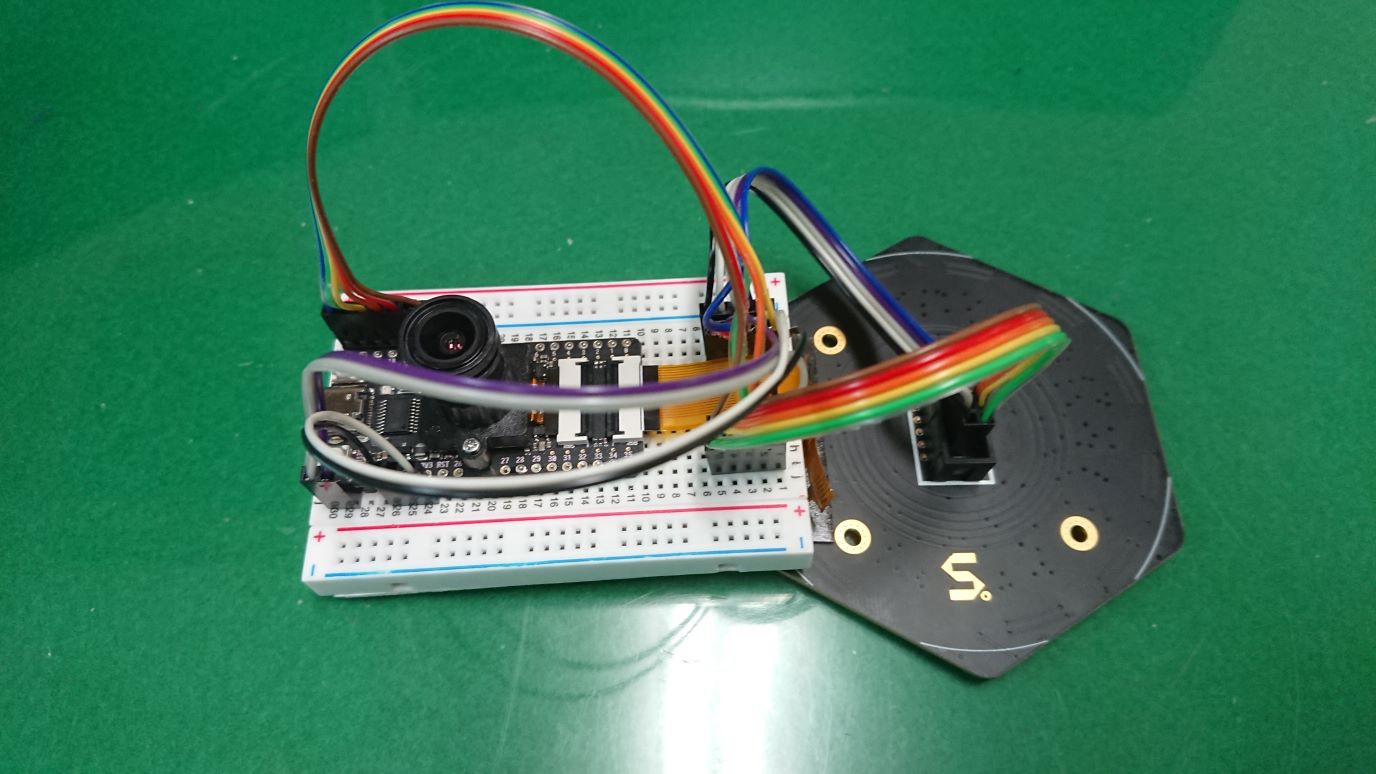
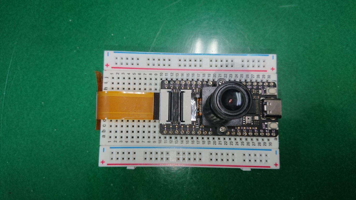
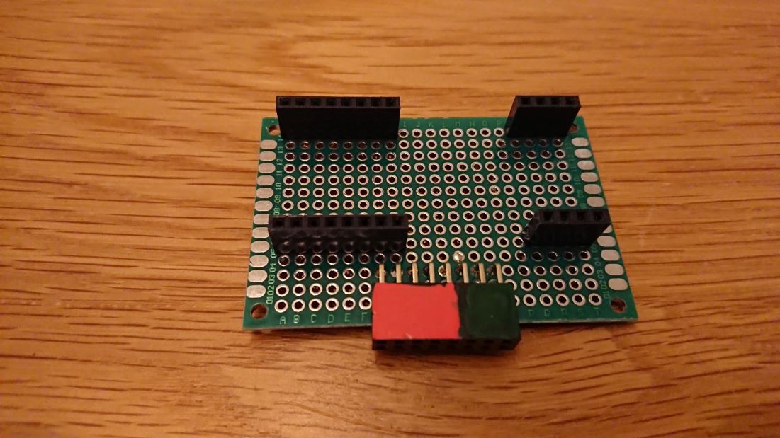
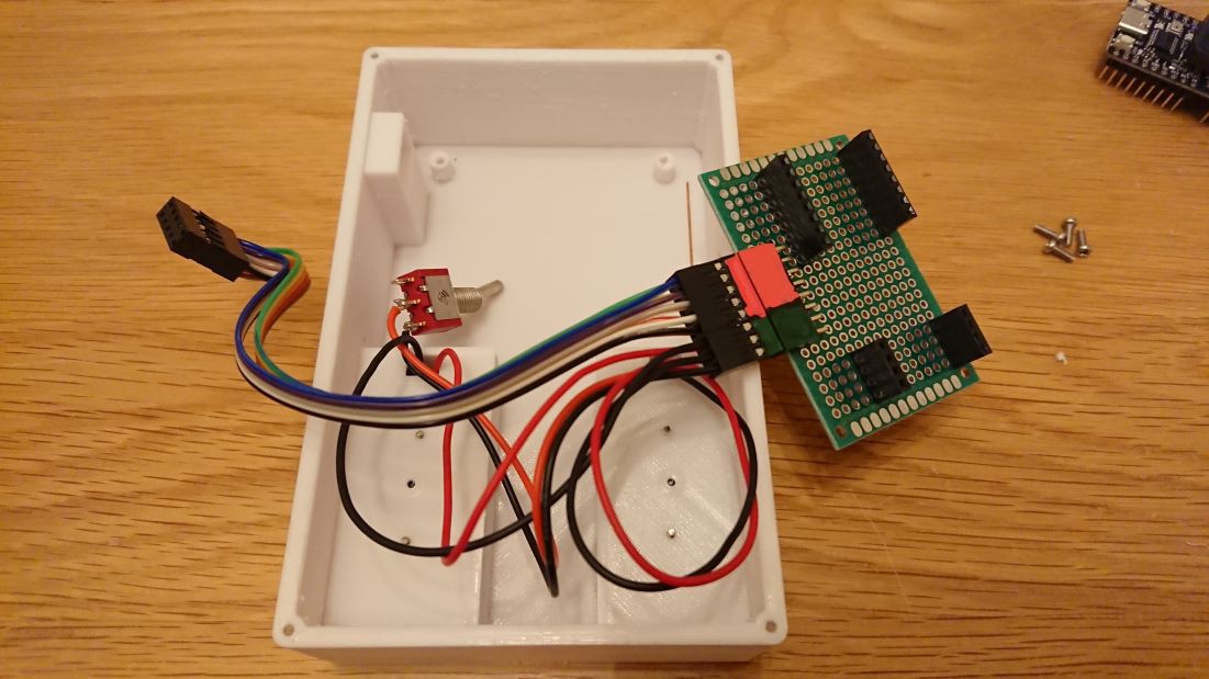
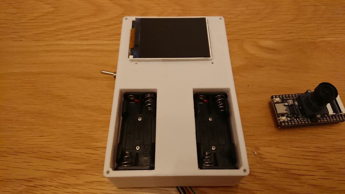
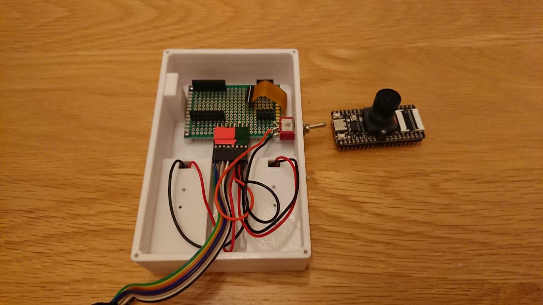
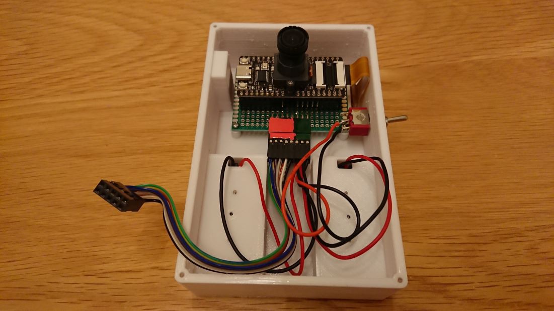
This device is equipped with a camera, a microphone array, and a microcontroller that can also be used for edge AI. 

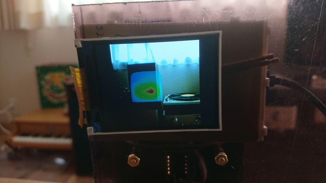
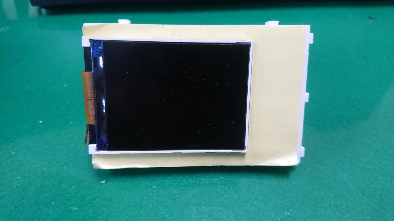
The microcontroller analyzes the sound information obtained from the microphone array and converts it into a color map, which is then overlaid on the image data captured by the camera and displayed on the back display in real-time. 

Since the color map of the estimated sound source position and the field of view (FoV) of the camera are significantly different, the camera lens is replaced with a wide-angle lens and the color map is cropped to adjust the display image.

Application:

This project can be used to visually confirm the location of sound sources for people who are deaf or hard of hearing. 

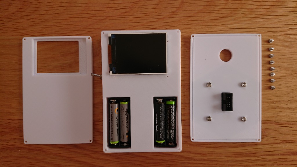
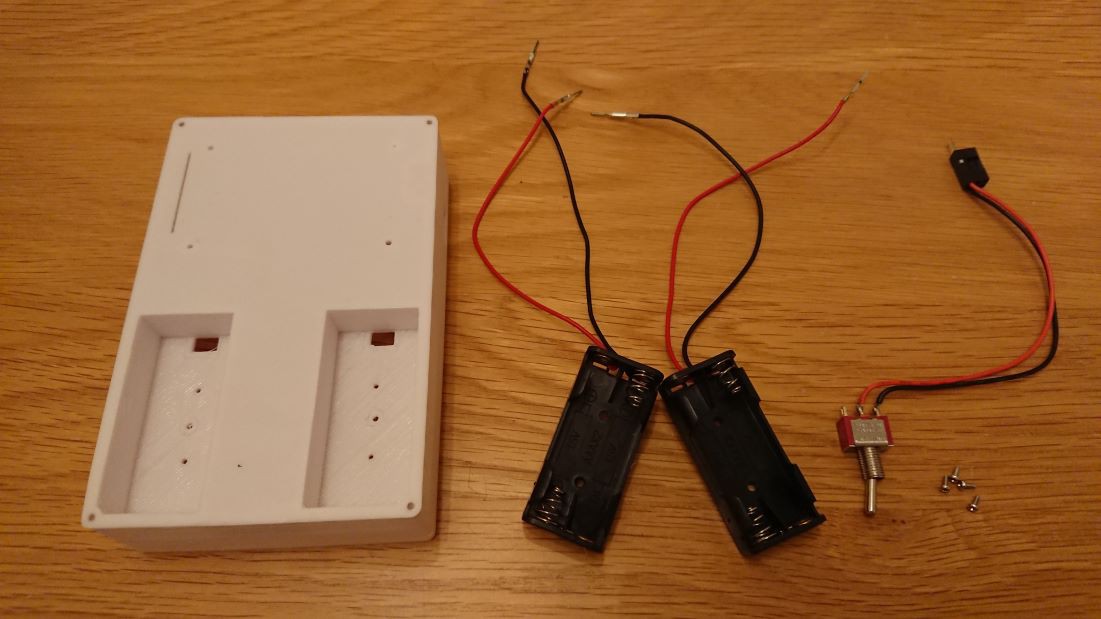
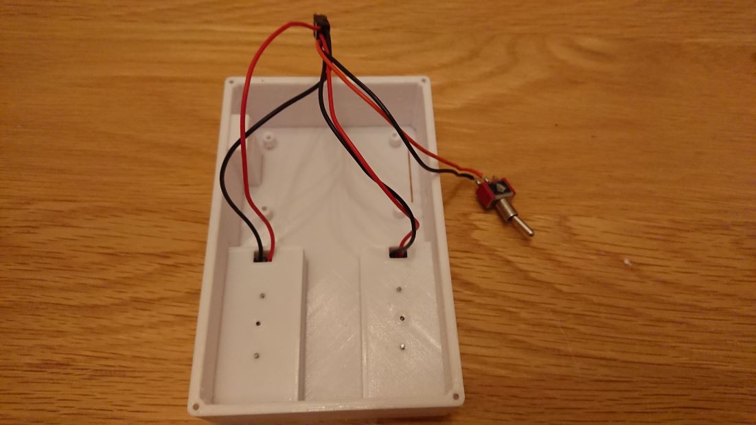
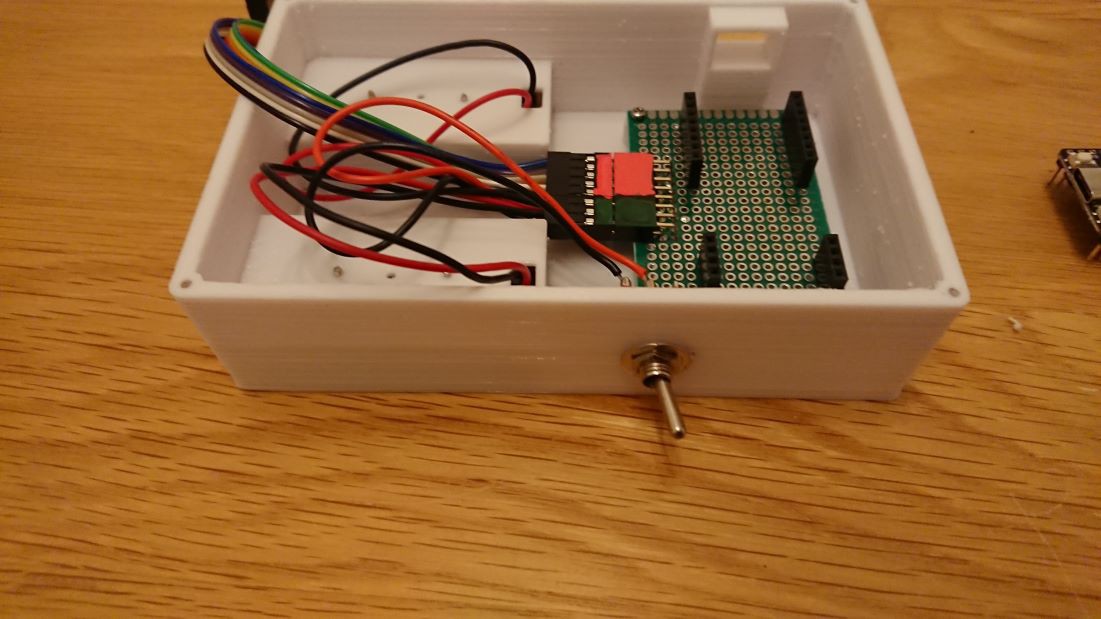
It is useful not only for people who are completely deaf, but also for those who have lost hearing in one ear and cannot detect the direction of sound. It was developed as a portable device powered by four Ni-H batteries of size AAA. 

In addition, it can also be used for cicada catching by people with normal hearing. With this device, the sound of cicadas can be visualized, so even children who are not good at catching cicadas can always find the location of the cicadas that are chirping.

The device was renamed to "Semi-tori Meijin" in Japanese, which means "Cicada-catching Master", because it makes catching cicadas so easy.

x-python - 2.78 kB - 06/19/2023 at 08:26

Download

Standard Tesselated Geometry - 158.87 kB - 05/10/2023 at 23:25

Download

Standard Tesselated Geometry - 69.42 kB - 05/10/2023 at 23:25

Download

Standard Tesselated Geometry - 41.88 kB - 05/10/2023 at 23:25

Download

  • 1 × Sipeed Maix Bit Maix Bit is a microcontroller board for edge AI from Sipeed. When purchasing, there are several packages to choose from, but the Maix should come with an image sensor and LCD.
  • 1 × Sipeed 6 + 1 Mic Array Mic Array is also available from Sipeed.
  • 1 × M12 mount F2.0 1.8mm lens
  • 2 × 2 AAA Battery holder
  • 1 × Toggle switch SPST alternate

View all 9 components

  • Built the Enclosure

    AIRPOCKET05/30/2023 at 03:21 0 comments

    I have verified the operation of the microcontroller and microphone array and have produced an enclosure.

    The enclosure has an additional AAA battery case for drive and a toggle switch for power.

    system image

    I made only one board to connect the wires and secure the microcontroller board.

  • Overlay camera image and sound image

    AIRPOCKET05/25/2023 at 05:14 0 comments

    In the previous tests, we were able to obtain the sound image. Next, we will capture a camera image and try to combine it with the sound image, and output it to the display.

    When combining the sound image and the camera image, it is important to align the field of view (FoV) of both images and bring the shooting axes as close together as possible. Ideally, the camera should be positioned at the center of the microphone array. 

    However, in this case, we will place the two sensors as close together as possible and make adjustments. Since the exact center of the field of view may be slightly offset, it is recommended to tilt the placement slightly so that the center of the field of view intersects at the desired distance from the target.

    Here, the camera and microphone array were tested on a polycarbonate board to which the camera and microphone array were fixed for testing.

    When you combine the images obtained from the camera and the microphone array, it will look like the following. The sound image is enlarged to a suitable size and then cropped to align with the camera image. The code can be written very simply using MicroPython's OpenMV.

    TV audio visualization example.

    You can also visualize the music playing from the audio speakers.

  • Microphone Array Test

    AIRPOCKET05/16/2023 at 03:46 0 comments

    Now, let's get back to the microphone array test. First, just for testing purposes, we'll connect the MaixBit and the microphone array using a breadboard and jumper wires.    


    I wrote some test code that converts the sound information obtained by the microphone array into a heatmap of the sound source location and displays it on the display.

    You can confirm that the location of the heatmap is moving according to the location of the chime.


  • Rewriting the firmware

    AIRPOCKET05/12/2023 at 13:22 0 comments

    It's Friday night, so I'll make some progress. I wanted to write the latest version of the firmware, but since I'm using a new PC, the USB serial communication device driver was not installed. Since MaixBit uses CH552, I need to install the driver on my PC following the instructions on this page.

    https://wiki.sipeed.com/soft/maixpy/en/get_started/install_driver/bit.html

    The method for rewriting the firmware is explained on this page.

    https://wiki.sipeed.com/soft/maixpy/en/get_started/upgrade_maixpy_firmware.html

    Also, while it is not directly related to this project, following the tutorial will allow you to easily try face detection using yolo with edge processing.

    https://github.com/knorth55/maixbit_tutorials

    If you have not experienced a demonstration of Edge AI using microcontrollers before, this is a great opportunity to try it out. I highly recommend giving it a go.


  • about MaixPy

    AIRPOCKET05/11/2023 at 22:54 0 comments

    For the development environment of this device, we used MaixPy, which is a MicroPython-based platform. Before starting development, we checked the documentation page.

    https://wiki.sipeed.com/soft/maixpy/en/index.html

    The basic usage is similar to MicroPython, but it includes APIs specific to the K210 chip, such as FPIOA, KPU, and FFT. KPU is a very useful API for performing operations related to edge AI, while FFT is used for performing FFT calculations. Additionally, since OpenMV can be used, it is very easy to perform image processing. We also used OpenMV for this project.

    Furthermore, APIs for controlling sensor modules developed by Sipeed  are also provided.

  • about Maix Bit

    AIRPOCKET05/10/2023 at 23:44 0 comments

    Before starting the program, let's do a little research on the hardware.

    Official information about Maix Bit can be found here.

    https://wiki.sipeed.com/soft/maixpy/en/develop_kit_board/maix_bit.html

    https://dl.sipeed.com/shareURL/MAIX/HDK/Sipeed-Maix-Bit


    The main specifications are as shown in the table.

    ProjectDescription
    CPUDual-core 64bit RISC-V / 400MHz (double precision FPU integration)
    Memory8MiB 64bit on-chip SRAM
    Strage16MiB Flash, support micro SDXC expansion storage (max 128GB)
    Screen2.4 inch TFT, screen resolution: 320*240
    Camera200W pixels (actual use 30W), 0V2640 model M12 camera
    TF card slotMultimedia resource expansion, support large-capacity storage

    GPIOs are arranged as follows.

    A relatively large number of GPIOs are available, and communication protocols such as SPI, I2C, and UART can be easily implemented.
    This is good news as wearable devices that convey sound direction through vibrations and other tactile feedback are also planned for the future.
    Circuit diagrams and 3D data are also available, so development can be carried out quickly.

  • Development Environment

    AIRPOCKET05/09/2023 at 06:59 0 comments

    MaixBit can be developed using MaixPy, which is a MicroPython-based language. 

    Maix IDE

    The development environment is MaixIDE, which is used to connect to the PC via USBSerial. 

    https://dl.sipeed.com/shareURL/MAIX/MaixPy/ide/v0.2.5

    Firmware

    The firmware is available on this website, and "maixpy_v0.6.2_84_g8fcd84a58_minimum.bin" version is used to avoid wasting RAM. 

    https://dl.sipeed.com/shareURL/MAIX/MaixPy/release/master/maixpy_v0.6.2_84_g8fcd84a58

    Kflash-gui

    Kflash-gui was used to write the firmware. 

    https://github.com/sipeed/kflash_gui/tree/master

    Code created with MaixPy is saved as main.py on a microSD card and loaded automatically at startup. Alternatively, it can be saved and executed in Flash memory. 

    uPyLoader

    uPyLoader was used for reading and writing to Flash memory. 

    https://github.com/BetaRavener/uPyLoader/releases

    These tools are very useful when developing K210-based boards, so it is recommended to prepare them in advance.

  • Connecting Microphone Array and Microcontroller

    AIRPOCKET05/09/2023 at 06:24 0 comments

    We will connect MaixBit and the microphone array. The correspondence between the pins to be connected and the GPIO is shown in the following table.

    MaixBitMic Array
    PIN23MIC_D0
    PIN22
    MIC_D1
    PIN21MIC_D2
    PIN20MIC_D3
    PIN19MIC_WS
    PIN18MIC_BCK
    PIN17LED_CK
    PIN15LED_DA
    3V3VIN
    GNDGND

    We connected them with a jumper cable, and it looks like the picture below.

  • Check the Micro Controller

    AIRPOCKET05/09/2023 at 05:59 0 comments

    The microcontroller used in this project is also made by Sipeed. It is called the Maix Bit and was released a few years ago. It features a high-performance SoC called Kendryte K210, which can be used for edge computing.

    AI devices evolve quickly, and boards from a few years ago may seem outdated, but I think the K210 is still a very capable device with plenty of potential for use. 

    There are several types of development boards that use the K210, including those with many GPIO pins, smaller sizes, and those with an integrated enclosure, among others. The Maix Bit is a well-balanced type that has many GPIO pins and a compact size.

    In addition to GPIO pins, the board is equipped with connectors for a camera and an LCD display. These camera and display will also be used in the device we are building this time. The display is a 320×240 pixel LCD, and the camera is an OV2640 type that uses an M12 lens mount, allowing the lens to be changed if necessary.
    Although we will not be using it this time, the board also has one MEMS microphone.

    When testing MaixBit, it is convenient to use a 400-hole breadboard as shown in the photo.

  • Check the microphone array

    AIRPOCKET05/09/2023 at 04:58 0 comments

    The microphone array used in this project is the 6+1 microphone array from Sipeed. It has a total of 7 MEMS microphones mounted at the vertices and center of a hexagon, with 3 microphones arranged along each of the 3 axes.

    There are 10 pins on the back of the array for data transmission and reception.
    In addition, there are 12 NeoPixel LEDs mounted around the perimeter of the PCB, which can be used to display the direction of the sound source using only the PCB.

View all 10 project logs

  • 1
    Installation of the Battery Box

    Attach two battery boxes containing two AAA batteries each using screws.

    Connect the power toggle switch cable, link four batteries and the switch in series, and construct a circuit that connects to the microcontroller's VCC and GND

    The cables are threaded through the holes in the enclosure and pulled into the interior of the enclosure.

    The connectors are consolidated into a 2x3 PIN QI connector. As the toggle switch interferes with the board for controller fixation, it will not be secured in place; only the wiring will be done.

  • 2
    Board Installation

    The board has been fabricated using a universal board.

    The universal board serves three purposes.

    1. Securing the Microcontroller Board

    2. Wiring the Power Supply to the Microcontroller.

  • 3. Connecting the Microphone Array Board to the Microcontroller.
  • To secure the microcontroller, arrange the pin sockets as shown in the photo.

    Under the board, there is a 2x8 PIN QI connector. The red-highlighted 2x8 PIN section is for connecting to the microphone array board, while the green 2x3 PIN is for power supply. The power supply is wired to allow the battery and switch to be connected in series to VCC and GND.

    First, insert the cables for the power line and the sensor, then secure the board inside the enclosure.

    Once the board is secured, proceed to fix the toggle switch in place.

  • 3
    Attach the Microcontroller Board.

    Attach the display to the back of the enclosure using double-sided tape. Thread the cables through the slit into the interior of the enclosure.

    Attach the microcontroller board to the fixation board.

    After attaching the microcontroller board, secure the FPC (Flexible Printed Circuit) of the display to the connector.

  • View all 5 instructions

    Enjoy this project?

    Share

    Discussions

    Matthias Schibli wrote 07/26/2023 at 11:20 point

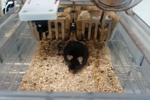
    Can you elaborate a bit on how calculating the direction of the sound source works? 
    Just skimming through the code, it looks like its only magnitude based, not looking at the phase of the signal, is that true? Sounds like a pretty big shortcut. 

      Are you sure? yes | no

    AIRPOCKET wrote 07/27/2023 at 08:38 point

    The API is used by importing a module called MIC_ARRAY.

      Are you sure? yes | no

    Similar Projects

    Does this project spark your interest?

    Become a member to follow this project and never miss any updates