 OzQube
This is just the start of the project. It will evolve!!!
0%
0%
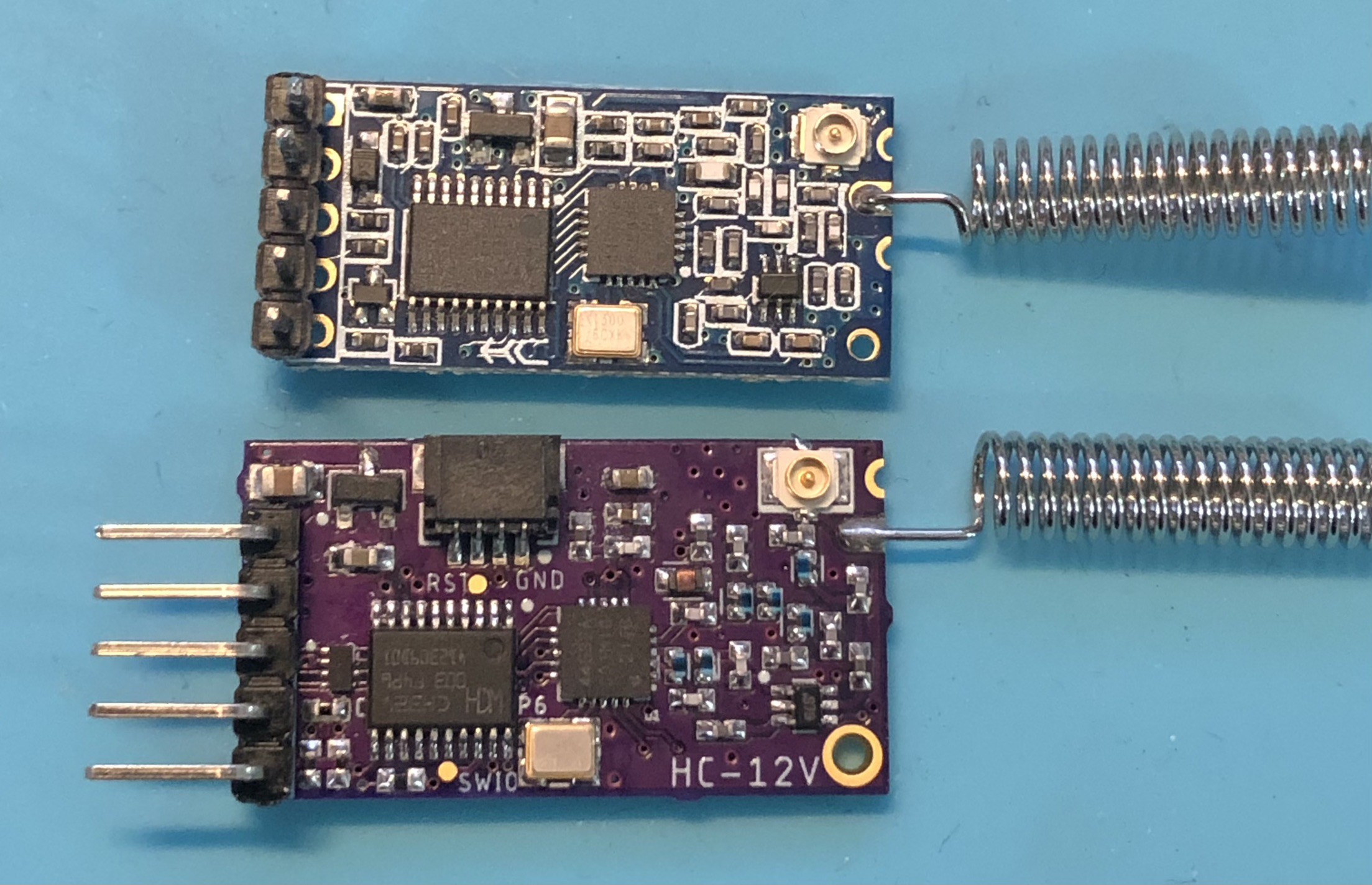
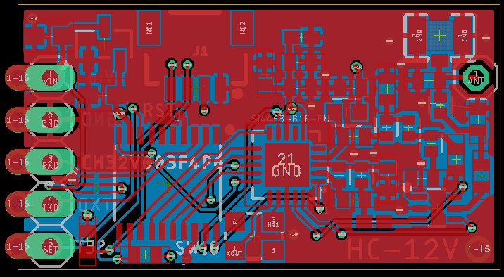
A Risc-V HC-12 433Mhz Serial Bridge
Updating the original HC-12 with a CH32V003
Become a Hackaday.io member
Already have an account? Log in.
Just one more thing
To make the experience fit your profile, pick a username and tell us what interests you.
Pick an awesome username
hackaday.io/
Your profile's URL: hackaday.io/username. Max 25 alphanumeric characters.
Pick a few interests
Projects that share your interests
People that share your interests


 Jacob Hahn
 Ryan Logsdon
 Matias N.
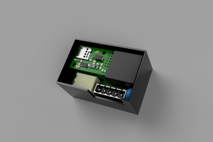
 Nicolò
in my opinion on board (feather format https://learn.adafruit.com/adafruit-feather/feather-specification ) is important power
for example step up down from 0.5V to 25V (AA, 18650 etc) and add a 5 buttons and alphanumeric screen , 5-8 chars