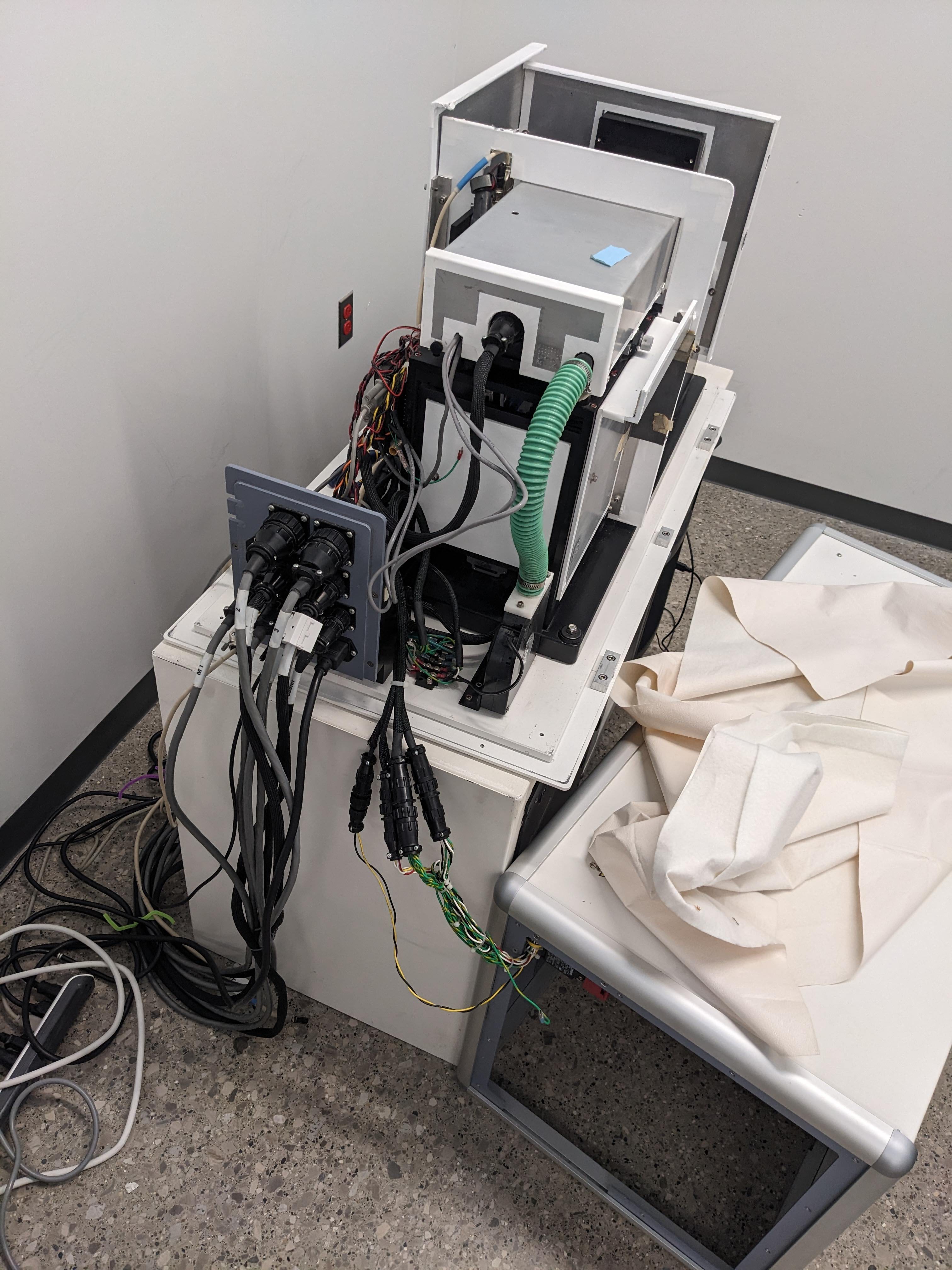
• The Short Scan, 2D images, Saving my Dying Source and other blitz misc

    Ahron Wayne11/15/2023 at 22:53 5 comments

    Okay, this will just be another schmorgasborg update as again, I haven't been doing 

    nothing, but it doesn't really fall into the neat little buckets like "changing the source" or "putting it on the truck" like in the first weeks. So:

    0: Guess who won a thing! https://scrollprize.substack.com/p/segmentation-tooling-2-winners Woohoo!


    That pays for the scanner and the source and all the other random little doodads, just about! 

    1: The super blurry scans we saw early are a thing of the past because of... the SHORT SCAN! 

    from XRayPhysics.com:

    In most lab CT, just like in the gif above, the object or source/detector rotate a full 360 degrees to scan the object. Which kind of makes sense, because that's what you would do with structured light scanning, or photogrammetry. But in reality, the minimum angle of rotation for a complete reconstruction is actually just 180 degrees! (+ fan angle). This is because, the x-rays go through the object. The projection of the object is the same 180 degrees apart (ignoring geometric magnification differences). You can see this in the reconstruction in the gif above; the reconstructed circle is complete at about the half way mark for the rotating source. 

    The rest of the 360 degrees is actually somewhat redundant! Ideally, more samples increase the signal to noise, but this is still kind of weird to me that it's the standard because by default some of the object is sampled twice and some is only sampled once. 

    The problem is that in our system, our rotary axis is super wonky in an as-yet-undetermined way. And this means that after the 180 degrees rotation, the object does not actually return to the exact same position, and the extra projections are even worse than redundant. You've got two good datasets fighting each other. I noticed this when I chose the "short scan" reconstruction method and the recon got way better, even though I was throwing away nearly half of the projections. 

    So now scans are way way better! And I can scan and make STLs of really important things like:

    Tiny resin print, professor's son's babytooth, snicker's. 

    2: I've been using the scanner for 2D images a lot! 

    Here's a picture of an old foil pokemon card! It's definitely not part of a project I've been working on for 2 years. I certainly haven't been collecting a large dataset for being able to look inside the unopened pack with simple 2D projection images. Incidentally, if you have experience with supervised convolutional neural networks for pix2pix, please reach out. 

    (guess who it is in the comments below!) 

    Or look at this starter thing? That's neat. 

    3: I came up with a scheme to extend the life of my source --- especially when taking series of 2D pictures where you would otherwise have to turn the source off, open the door, put the thing in, turn it on... the source has basically a filament light bulb inside, and just like regular visible ones the harshest thing is turning them off and on. And I was noticing that the power has gotten even lower than before. I try not to push it too far past 0.5 watts! 

    Daniel said something like "you can use the position of the tungsten shutter to know when it's safely blocking the source and have an Arduino move it to there whenever you open the door". I took this to mean, you can monitor the position of the tungsten shutter with an encoder and when it's blocking the source, change the voltage to 2.5v really quickly to make it stop rotating. 


    Hey, it works! And maybe I'll do daniel's idea eventually. Something like this is clearly what the original designers intended for when they created a tungsten shutter with an encoder attached to it. It's so much better than turning the source on and off and it REALLY works --- radiation meter sees no more than background inside the machine when...

    Read more »

  • Unwarping the Detector

    Ahron Wayne10/10/2023 at 02:00 0 comments

    There are many things that are wrong with this machine. This was one of them. I thought it would be easier to fix, but it wasn't. I also thought it would fix all of my problems, but it didn't. Anyway, I haven't been doing nothing these past few weeks --- I've been trying to unwarp the detector. What do I mean by "unwarp"?

    Well, modern flat panel X-Ray detector consists of a few main components, but for the sake of this problem there is a scintillator, which converts x-rays into visible light, and then the actual electronic detector, like a CCD, which converts the visible light into an electronic signal:

    The thing is, this detector is not so modern. Detectors weren't so much bought commercially from Viscom or whatever as they were often assembled as necessary for specific applications. This detector was engineered specifically for CT scanning by coupling a low noise (for the time) CCD to a scintillator plate... and in between those two things, a bundle of thousands of optical fibers. For more on that, see https://hackaday.io/project/191395-x-ray-ct-scanners-get-new-life/log/223337-image-offsets-ancient-scrolls-broken-shutters.

    We saw that offset correction work to make the image nice and crisp and remove the pattern and peeling, but it turns out there's also nonlinear warpage at play here --- warpage that is a major source of error unless it's corrected. Originally, it was corrected with a "BB grid" --- Item #2 of the 10 things in this image that I don't actually have: 

    So clearly, I had to make this "BB" grid. It nominally consists of 196 ~0.011 inch tungsten carbide balls spaced out 5mm (love the units), but surely I could fudge this a bit. For instance, I found out that you can get tiny lead balls for cheap for BGA soldering: 

    Now how to make a relatively precise grid? 

    Attempt #1: FDM printing didn't go so well on account of the balls are too small. 

    Attempt #2: SLA printing could produce the holes...

    ...but the process tends to warp with large flat things. 

    Attempt number THREE, I said, well, maybe I can just laser cut the dang thing out of acrylic. Actually, with a bit of tuning this worked relatively well!  

    Yes, putting 196 of these in a grid was as laborious as it sounds --- I actually rolled my finger over to get the bulk of them and then inspected and placed individually when needed. It wasn't trivial to make sure just one of the balls was in place either, and then I glued them and taped over for good measure. 

    There it is on the detector:


    And now we can see what kind of warp we're dealing with! 

    But that's.. hmm. Those balls are crooked. The detector can't be that warped. it's playing tricks with my eyes. The laser cut method is just too imprecise, and I didn't really want to introduce that kind of uncertainty to an already very uncertain calibration process, I thought. So I took the idea of Paul the Original Guy Back at EVS (again) and get a circuit board printed with JLC PCB, with the idea of using the copper pads as targets! 

    Now this --- save that aggravating misplaced pad you might spot that I had to cut out --- should work accurately, if anything would. (I also used it to determine the "mask" of useful pixels on the detector, incidentally). 

    This is the "transgen" program: 

    It's kind of cool, once you figure out the parameters that lead to a good search for the red boxes. It took a few tries. But once you do, and all the centroids are located, you get a file that now should hopefully unwarp and make things much more accurate! 

    And it does! More pats on the back! 

    I tested it by swapping the old file of a couple of recent scans. The results were, I would say, noticeable but not solving a few specific big artifacts, like rotation...

    Read more »

  • A visit to Scott's Valley: Resolving the Kevex Quest

    Ahron Wayne09/29/2023 at 03:51 0 comments

    Once upon a time, there was a company called Watkins-Johnson. It made microwave tubes and other microwave devices, mostly. But also equipment for electronic warfare, antennas, and semiconductors. Some of that equipment included technology involved in producing X-rays. And after a bit of a spinoff, that technology would become known as Kevex. 

    KEVEX. It was the place to be in the 80s and 90s if you were in the land of x-ray --- so popular that in the early 2000s it got bought by Thermo-electron corporation, becoming Thermo-Kevex tubes. And then with the merger of fisher scientific, simply Thermo-Fisher tubes. Known especially for being small and portable: In fact, that's what the PXS in the PXS-925 stands for: Portable X-Ray Source. 

    How do I know all this? I got a tour! 

    That there is John, X-Ray engineer of 19 years and very gracious host. The trip was borne out of my very long quest to obtain some basic information on the tube for our system to be able to safely drive and maybe service them and such. Now I'm not crazy enough to fly out to California just for this, but I WAS going there for work anyway, so why not stop by? 

    *(Warning: Incorrect info in the next paragraph)*

    I wish I could show you all of the AWESOME things I saw. This is not a factory where they put a couple of components together and slap a label on them. This was the real deal. They have a glassblower who makes the tubes BY HAND. (Out of a particular brand of shot glasses, I thjnk)? The cathodes come from the guy who owns Cathode.com. Gas is vacuumed out of oil, contaminants are baked out in big ovens, spot size is checked with intensifier screens. I wore a film badge. I learned a ton, I think, not that I really remember enough in detail to explain it. It was all one big x-ray factory blur, a Disney World for x-ray nerds. 

    But how about one tidbit --- how to test if, for the dead source at my friend's wood shop, whether it's the tube or the high voltage source that's bad. Stand the source up on its end, vertically, "so the oil doesn't leak out". Pull out the tube (you can do this, apparently), and then slowly, carefully, raise the high voltage up. If it still goes up, the HV is good, the tube was bad! Otherwise, the HV is bad, the tube was good! Good luck assembling it back together without air bubbles, but at least now you know! 

    Oh, and don't raise the HV too fast or you might get a room full of oil. 

    *Update with correction: John has informed me that they do NOT make the glasses out of shot glasses! It's blown there but the material is from a major supplier of scientific glass. And that the cathode.com guy is just a friend, also local and part of the unique ecosystem of businesses that made the factory possible. 

  • A Working Shutter

    Ahron Wayne09/23/2023 at 01:44 0 comments

    Finally. 

    The secret? In the end? Calling the number on the back of that motor driver. I was talking to an engineer in about 90 seconds, and he was emailing me the datasheet and user manual five minutes after that. He knew which line of motor driver product I was talking about, and keep in mind the manual says that the requirement was for Windows 95. Way to go, Shawn from Faulhaber! 

    Those are uploaded to the files list now --- honestly, the driver is incredible overkill for the main task of, like, spinning at a constant and adjustable speed. With digital control you can tell it to home, run macros, report the speed and adjust PID loops, compensate for backlash, set external triggers. And with DeviceNet address and coordinate between thousands of motors. 

    I wanted to make the thing spin at a constant and adjustable speed. And unfortunately, I couldn't get said digital RS232 to work --- maybe eventually, but with all that frustration... why not just take advantage of the analog input for speed, just in case all you want to do is make the thing spin at a constant and adjustable speed? 

    Analog input: Zero volts, spin in one direction. Five volts, spin in the other direction. 2.5 volts, stop. And then everything in between, at 10 bits of ADC. THANK YOU, SHAWN! 

  • Image offsets, ancient scrolls, broken shutters

    Ahron Wayne09/18/2023 at 01:50 2 comments

    Don't worry, I'm not planning on running the x-rays like this. The cover had to come off because it was probe-y probe-y time again, as we try to fix the shutter (seriously? Again?) which I blew up by accident a few days ago. Actually just the driver board, thankfully.  

    I've spent the last couple of days haaaaaaaaaaaaaating the shutter server, again, with a passion that burns within all of my soul. Basically, since I destroyed the replacement driver board, I wanted to at least try again to get the original to work. And why not? It's perfectly tuned for the motor already... you just CAN'T CONNECT TO IT !@$@$@$%@%@$#%#%! 

    There's the box that controls the motor, which it turns out even has an encoder. Which would mean it could be used for such very useful and safe things such as moving the tungsten shutter to cover the source when you want it to. We know the motor can be held in position and stably, thanks to some knowledge gleaned while trying to connect to the shutter server, but if we get into that we'll be here all day. Sigh.

    I don't think we had much of a warranty anyway. Daniel knew about all the stuff that was inside here, but unfortunately even he didn't spot the magic analog make it go whirr and how fast button. 

    Before the current state of machine malaise, I did some reading and experimenting with calibration, recon settings, and scan acquisition. I think the coolest .exe power I got is applying offset images. You can see in this (FULL RESOLUTION 1X1 binning!!) image, squee, that the detector over the years has sustained a bit of damage: 

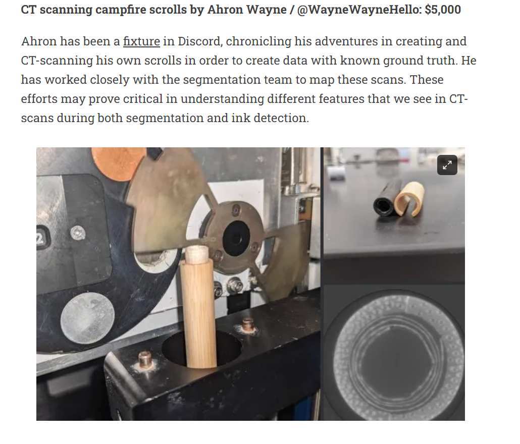
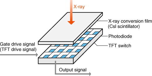
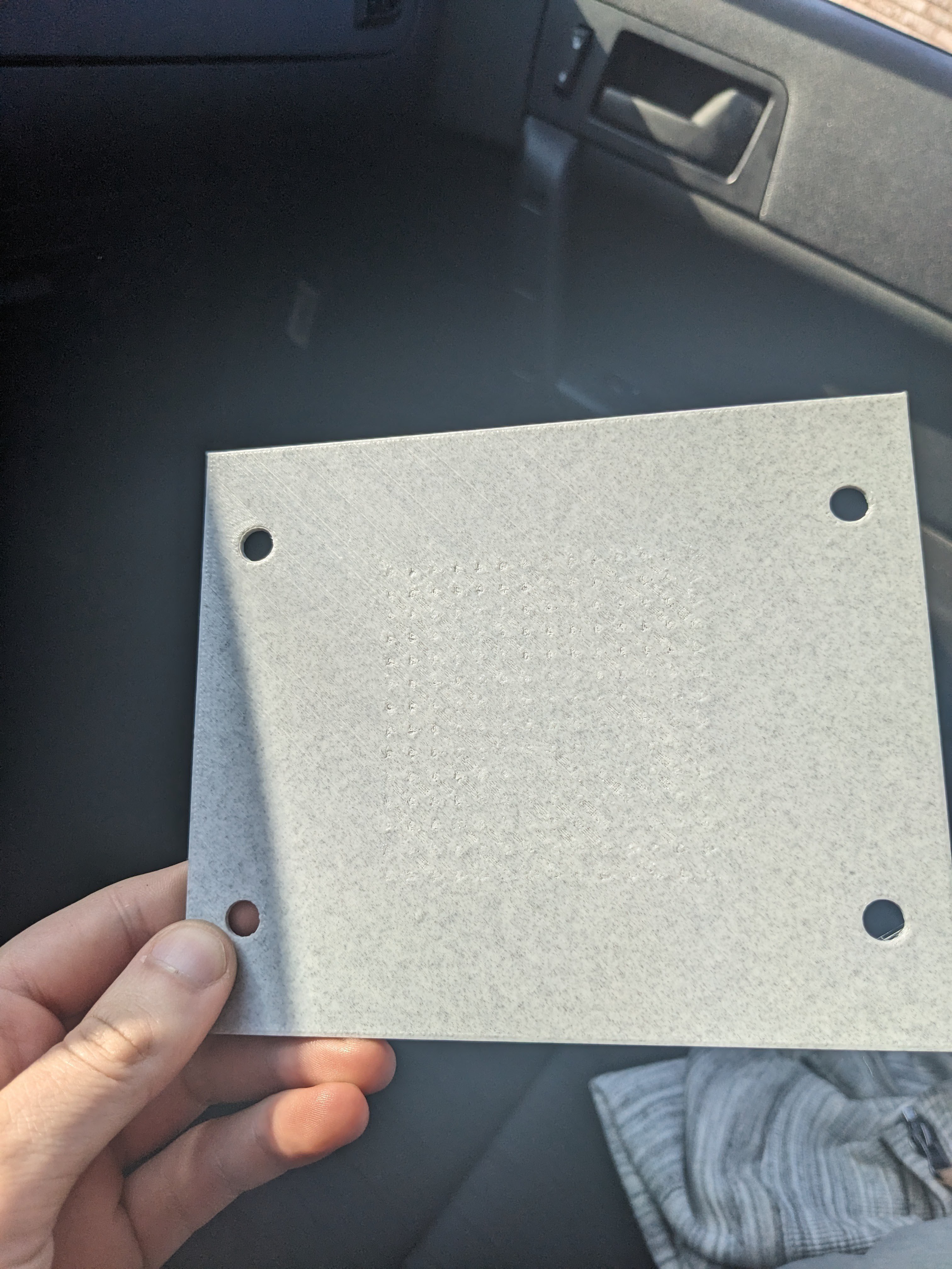
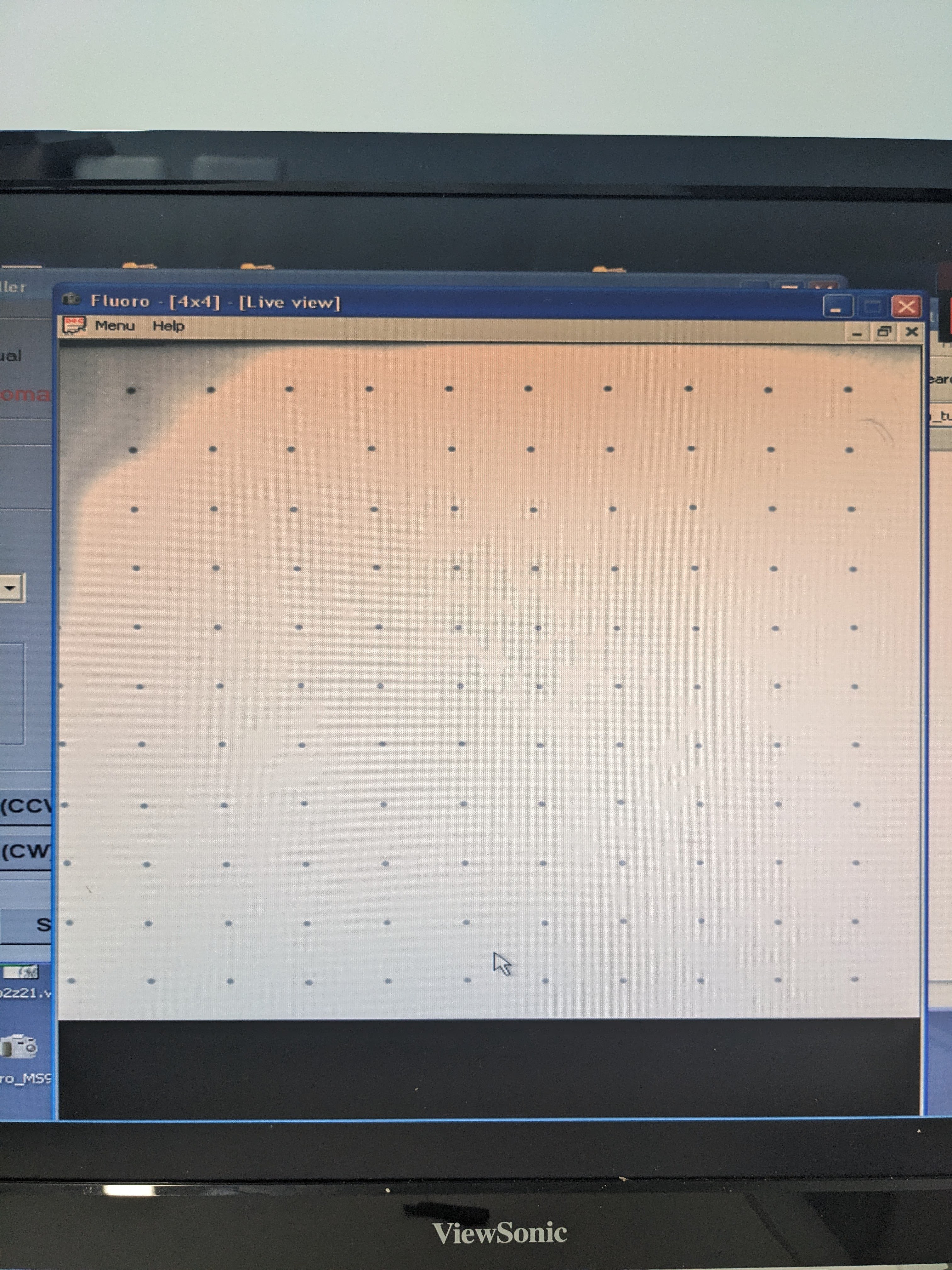
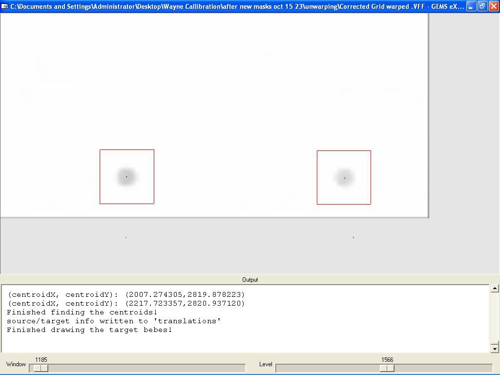
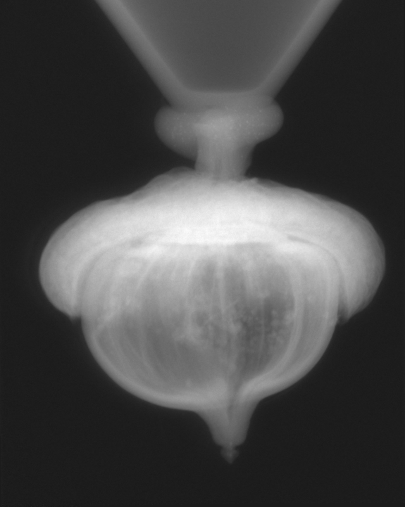
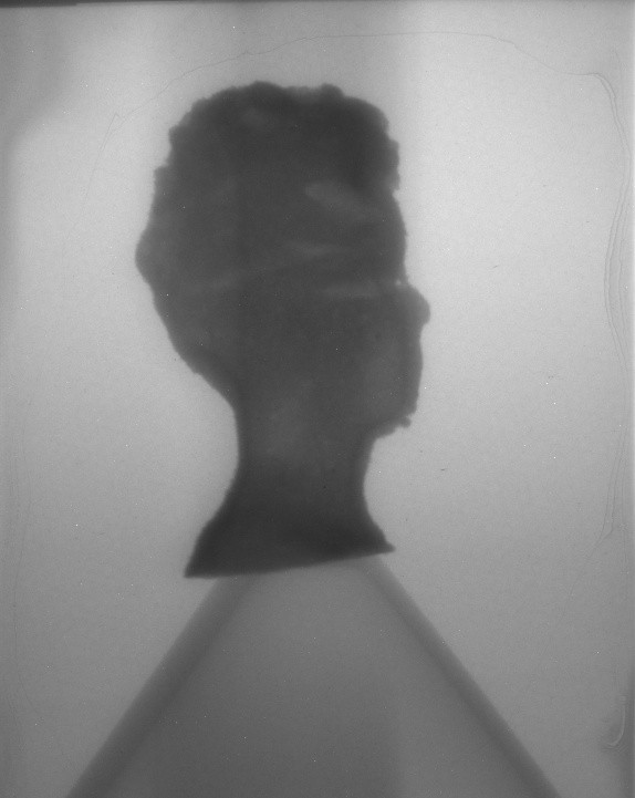
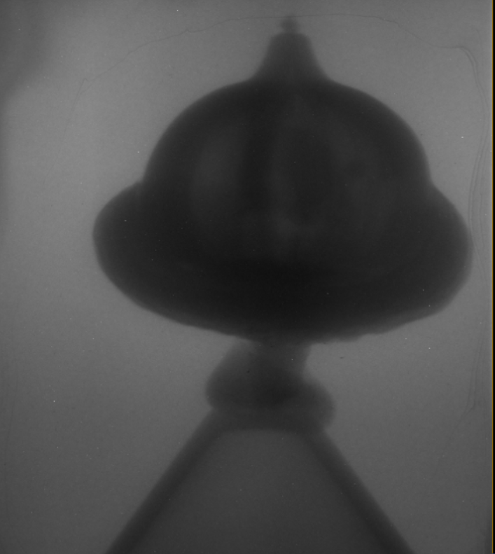
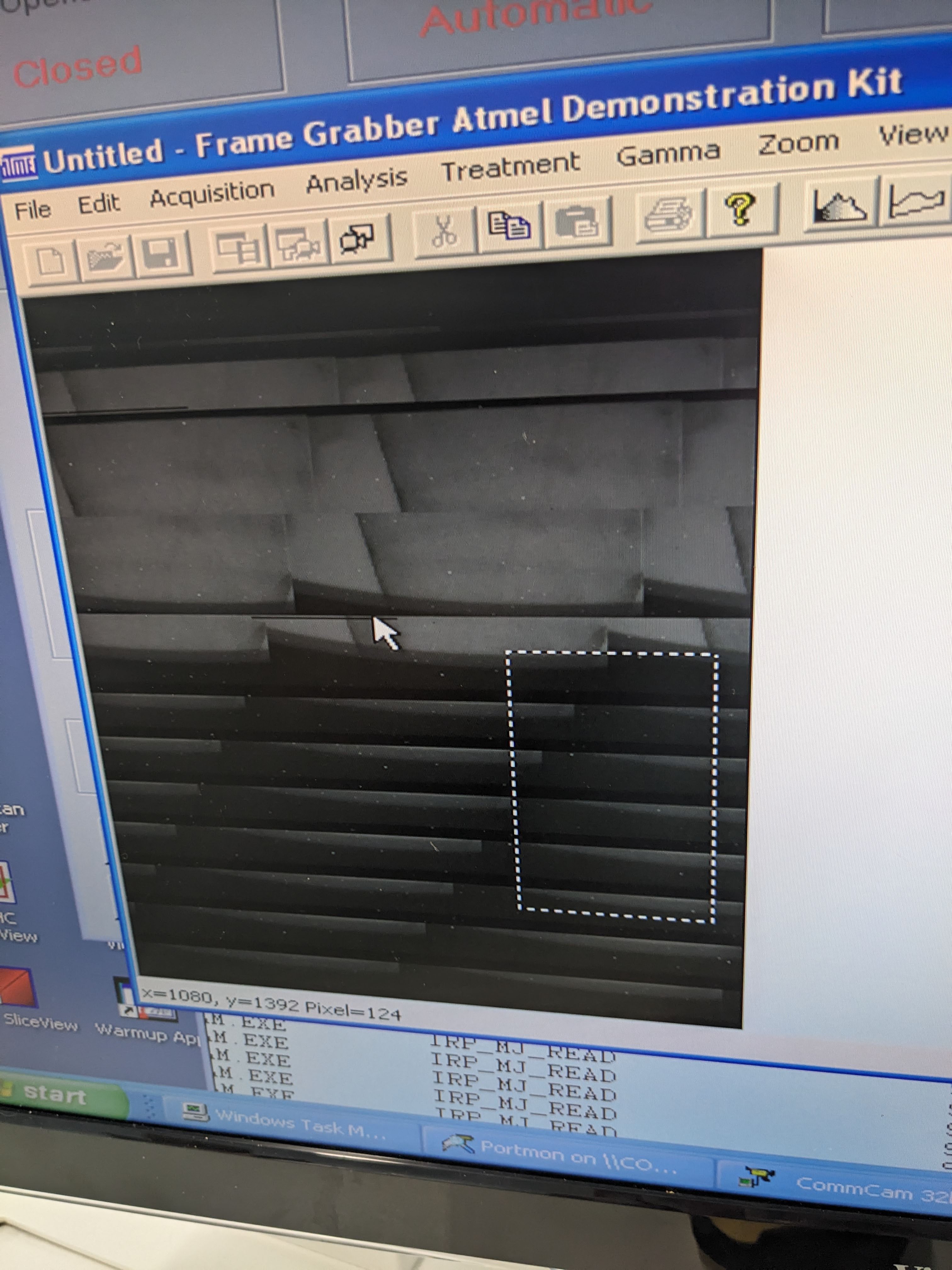
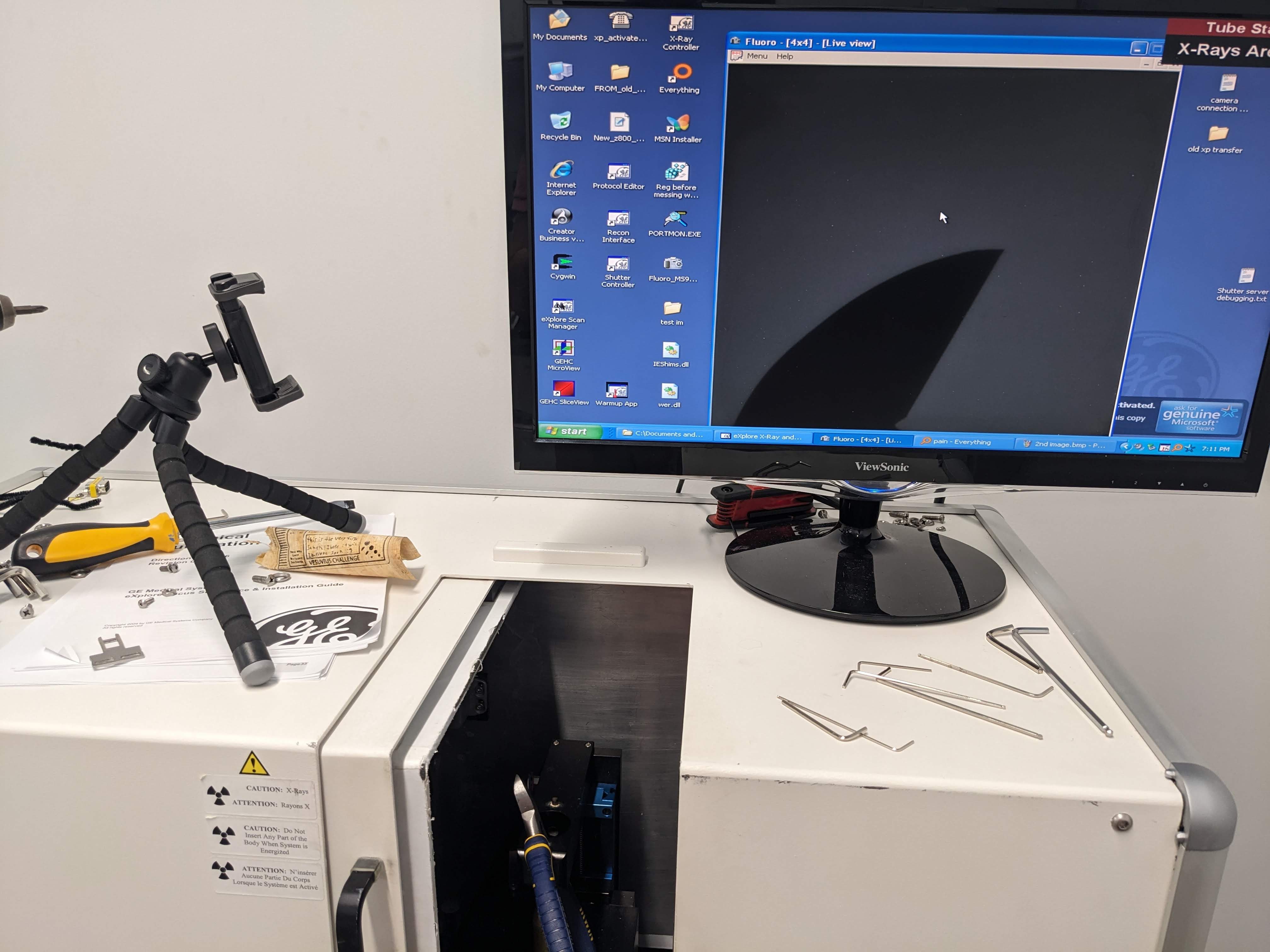
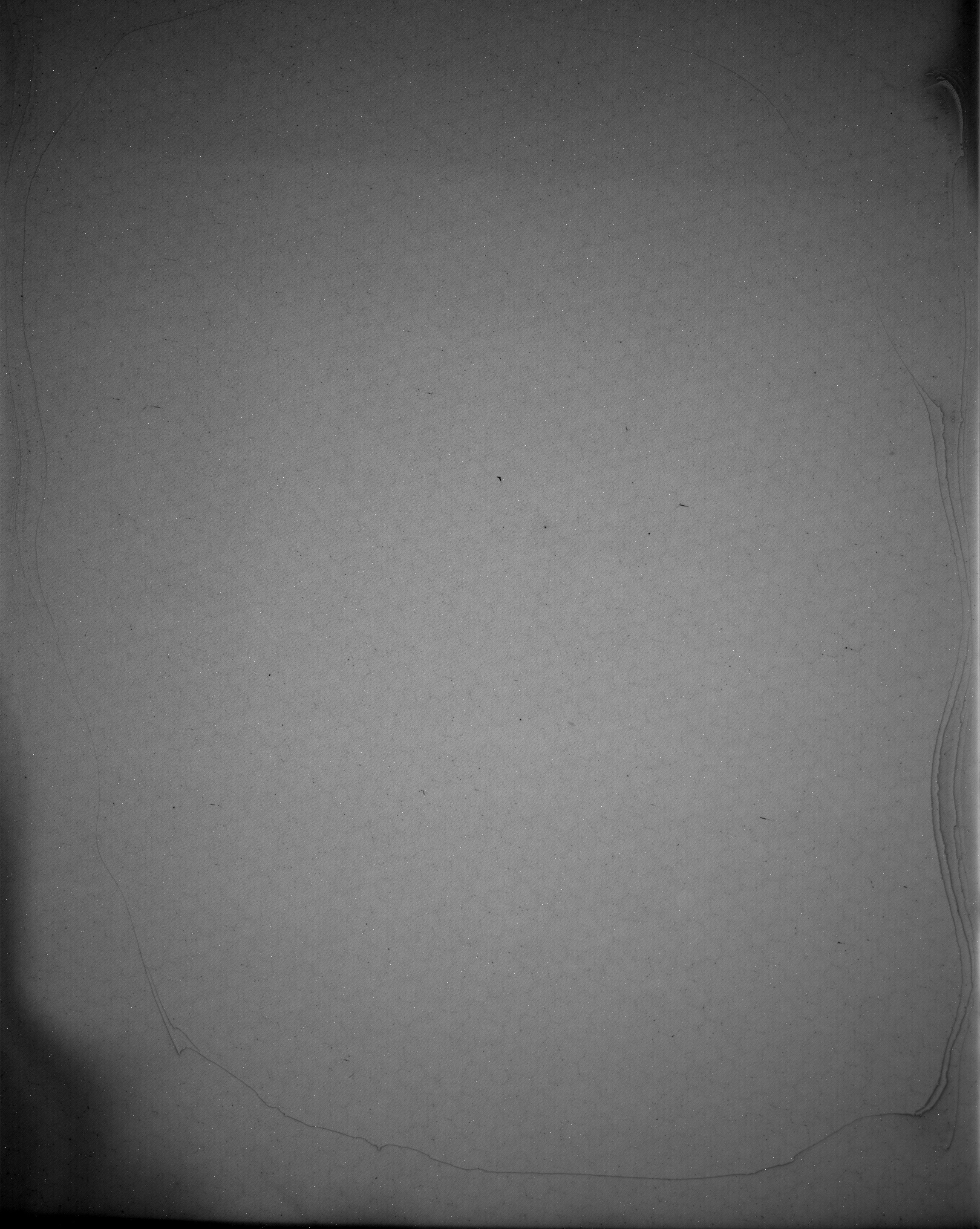
    This is still kind of an awesome image IMO. It's 1x1 binning, and the detail of the detector backing, or fiber optics, is actually pretty cool. To take a 1x1 bin image needs a long exposure time, but our shutter couldn't be ramped down that slow. So instead we just average 10 times, which results in the same SNR as a full exposure image pretty much. 
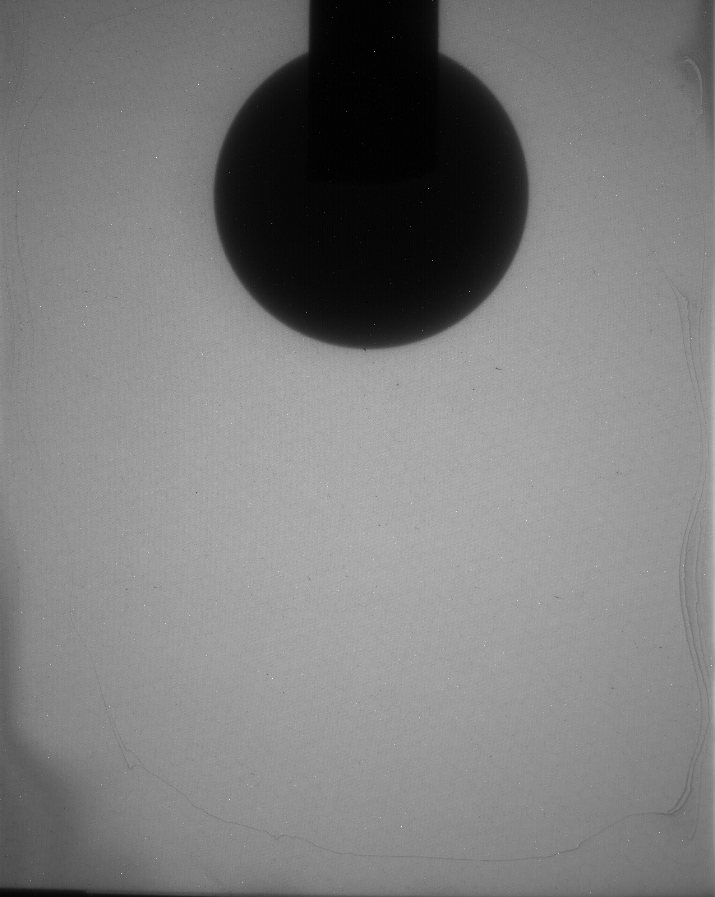
    But yeah, that pattern! And the peeling, yikes! the color is all different! It's practically dirty! What's that gonna do the scans of this round thing?

    Not much, if you just apply the blank picture of the detector as an offset image. 

    Like a cheat code for image processing. There's a lot of chasing the last little bit of quality like by taking multiple references, spaced out through the scan, but 99 percent of the benefit is from just doing it at all. Even JPEG knows how much cleaner this image is; it's only 30 percent of the size of the uncorrected one. 


    There's more, for sure! The machine had already started proving useful to an applied research task. I'm not sure if I mentioned this yet or not, but this project was born partially out of the Vesuvius Challenge, a very cool and suspiciously side-quest-y goal to read some ancient scrolls that fell into a volcano using x-rays. I've been doing experiments with carbonization to simulate scrolls, with the intent of scanning them. This is now a reality. 


    Cross section of carbonized papyrus, inside bamboo tube! 

    So here's to the future --- we're there, nearly, with just the occasional setback! To ancient scrolls! To image offsets! To a working shutter, eventually. 

  • It's officially a computed tomography scanner!

    Ahron Wayne09/04/2023 at 21:58 0 comments

    Yay! 

    Since the last post: 

    The shutter has been made less crappy using a dedicated BLDC driver for motors with hall effect sensors. It's not set up right still, but the shutter is moving slowly enough to do real exposures of about a second long. 

    So let's do a scan! 

    First we have to choose our protocol, where we define the exact parameters for the scan. Since we're sticking with 4x4 binning (or pixel ganging), we don't need that many projections or exposure time or averaging, which is perfect for us. For my initial testing, I'm using a voltage of 60 kv and a current of '30' uamps, which actually leads to about 16-20 microamps. And I'm placing the object at such a position to get a voxel size of about 50 microns. Lastly, I am, for instance, taking 200 projections --- a rule of thumb is 1 projection for each pixel in x/y the object crosses while rotating, but in practice you can still get a lot of info from less than that. The scan lasts about 7 minutes.  

    As an aside, the program is really annoying in that it won't let you run unless the X-rays have been warmed up in the last 15 minutes (to a higher voltage than I actually want to run which I don't think helps the tube). So I hack it to run anyway by just changing the system time to when it was last warmed up according to it. Yolo. 

    And to my surprise, you hit that "scan" button and it just starts going. I was worried that the the motors would be asynchronized with the shutter, but for once it seems like something with the shutter works correctly. 

    After the scan is done, it turns off the x-rays automatically (we'll see what I can do about that) and then prompts you to remove the sample for taking bright and dark field images. These are images with nothing in the way and can be used to mitigate various things like, a damaged scintillator or dead pixels. 

    Goodbye, peeling scintillator! 

    This is a huge boost to quality just with that offset difference. Like an image processing miracle in my opinion. 

    Now, after my first scan was run, I hit "recon" and nothing happened. Used to bugs and happy with the progress I had made I went home and came back the next day to sort it out. Found that there's some kind of reconstruction server as well as a command line utility; after a restart, both work, with the command line utility being more ancient and robust but slower.

    And finally... after hitting recon. It does some filtered back projection and, ta-daaaaah, we have our reconstructed scans. 

    And then there's the 3D scanning aspect of 3D, computed tomography, where in the simplest form you just pick a greyscale value threshold that forms a surface and which can be exported as an STL.

    This is just one example, but it exemplifies the kinds of scans we'll be able to do with the machine. 

    So there you have it! Exactly three months from picking up the machines to getting one working! Let's see how much we can improve it, now. 

  • The original computer solves not all of the problems

    Ahron Wayne08/31/2023 at 16:32 1 comment

    Since our last post I changed the entire computer (again, I suppose). An HP-XW8400: Found on ebay at a decent price finally, this was what was originally used by the SP after upgraded from Windows 2000 to XP. 

    I hooked everything up and... problems.

    i mean, the recon interface hadn't worked before, either, but why not? So I then re-cloned the hard drive image, to this old physical hard disk, with the idea that I would be way more careful and methodical this time. Even that process involved fixing a bunch of small bugs --- like the hard drive image (160 gb) being too big for the hard drive (160 gb). 

    So let's take a step back at our little CT nook:

    The place is a mess. Most of the screws on the panels are off, as is the extra shielding. There are tools and allen wrenches everywhere. Four hard drives, a few computers, thousands of pages of documents, the old x-ray source, and every cable you can imagine. I've taken the machine apart and put it back together again, I've connected motors to external controllers, tracked down capture cards and service engineers and now finally I have most of the original hardware, and all the original software, on an original hard drive clone.

    And now the reconstruction utility opens! And like before I can move the motors. I can fire x-rays. I can see images. Everything seems to work. Everything but the shutter server. 

    It's supposed to be on port 3. Why isn't it on port 3? Why does the registry say it's supposed to be on port 3, when that's where the x-ray and motor controller is? Why doesn't it work on ports 4-6 either, which are the only other ports that another working system has registered? Why doesn't it even try to communicate with those ports when they're open? HOW COULD IT BE ON PORT 3 IF THE X-RAY MOTOR CONTROLLER IS THERE???

    ARGHHHHHHHHHHHHHHHHHHHHHHHHHHHHHHHHHHHHHHHHHHHHHHHH 

    The funny thing is --- I figured out that with the frame capture software, there's actually settings that will let it take images without the shutter at all, which confuses me to no end --- with all that trouble, why did they even bother with it? As an example, here's a blurry phone-shot live-view video of what appears to be a parasite in my acorn. 

    Unfortunately, the triggering for the camera and all the software still requires a physically rotating shutter. If the frame grabber software were better, perhaps I would forgo the shutter entirely, but the easiest path forward still looks like using the original scan and recon software, which is annoying for other reasons like that it makes you "warm up" the x-rays all the way to 90 kv even if you only plan on doing 60 kv scans which is bad for it. 

    And so this weekend I'll try to build a better shutter controller that works with the hall effect sensors hopefully, so I can drive it slowly and take real scans. 

  • "Sunday's Shutter Server"

    Ahron Wayne08/20/2023 at 23:12 0 comments

    The motor is a Brushless DC, which can mean a lot of things. This one runs on three phases. And it uses hall effect sensors. It took a lot of reviewing brushless motors and motors in general to understand that much, and I still can't drive it properly. 

    can, however, drive it inconsistently and badly by connecting the three phases to an electronic speed controller for drones and completely ignore the hall effect sensors. The result is a slightly jerky but moooostly stable at speed rotation, though it can't be run slowly. Also it makes a scary noise sometimes. Also also also, you have to crank start it by hand like an old plane propeller (really). It'll keep going but won't start back up if the power goes out and comes back on. 

    Pretty janky part of the setup, but compared to not turning at all..? I'll properly use the hall effect sensors will allow it to be driven slowly and precisely at some point (maybe while solving a bunch of other things simultaneously --- stay tuned). But for now, it does what it needs to, and lets me way more easily take images!

    There's my head! It's 3D printed and is made of glass. 

    This is a picture of an acorn! 

    In fact I've been able to do some crude scans while rotating --- set "Fluoro" to take 100 images while using a different program to set the part rotating. In theory, I should be able to take this info and guesstimate a few parameters for a crude reconstruction. 

  • First Images: Acquired

    Ahron Wayne08/16/2023 at 02:24 0 comments

    It started with the arrival of the rare and mythical, ancient ATMEL LVDS capture card that fit the custom 50 pin connector to the camera. Thanks, Trifoil, for sending a spare! 

    After installing, I was able to open up both Comcamm (for sending serial commands to the camera) and the FGT frame grabber program (for actually reading the images. Try as I might, though, all I got were blank images and occasionally something seriously buggy. 


    I was hoping I could set it to continuous readout mode and get some images, but apparently this very old CMOS sensor is unable to read out data while receiving new signal --- and the source is not capable of ramping on and off that quickly. In other words, there needs to be a shutter (in this case one that physically blocks x-rays) for it to work properly.

     The shutter in this system is a block of 2mm thick sintered tungsten-copper (insider knowledge), attached to a geared, brushless DC motor, placed in between the source and the object and also passing through a little optical interrupt switch. The switch, motor, and control unit are then connected in a mess of wires back and forth to the camera, the machine control, and a direct connection to the computer that has never triggered. The shutter seems to be what the whole system is built around, almost --- like a little heart beat --- and nothing will work right if the shutter doesn't run.

    So you can imagine my frustration where, despite trying different cables, different ports, different rates, different operating systems, monitoring the ports, monitoring the program, and so many kinds of turn it off and on again, still getting some variation of the above error when starting the shutter controller. What else can I do? Corner the person who designed it 25 years ago? 

    Hmmm... there's an idea... 

    Anyway, there's also a native program called "Fluoro" for getting a live view of what the camera is seeing. Thankfully, it would open despite the shutter not initializing, and I was able to confirm that the camera is, in fact, communicating info with this program. By making the shutter rotate manually, I could get some images of "snow" (dark current) to pop up on the screen --- and the longer I'd let it "expose", the more snow there would be. 

    A great sign! Now... how to try with the x-rays?

    In the long-term I can just drive that motor and its possible encoder with my own electronics. But in the short term --- that is, in the past few days --- I just wanted to get an image at all. Something to prove that the system works all together, that the scintillator hadn't peeled off or the cables hadn't run out of carburetor, or something. 

    Let's just say I found a way. So say hello to my first couple of proof-of-concept images.  

    That's some rolled-up papyrus (long story) and the blade of a random tool I had lying around. And I must say, I was surprised to see them look so good and sharp! I was expecting a terribly warped image or stripy lines that would normally be corrected for in a specific machine. But looking at these, this is functional for so many things right out of the gate --- and it'll only get better as I work my way through the calibration process. 

    But hey! I'd say I deserve a bit of a victory lap! About 10 straight weekends and a bunch of evenings, and of course, help from strangers and friends alike. We're getting there.  

  • Datasheets for PXS5-925 KEVEX Thermo-electron Thermo-fisher SCIENTIFIC X-Ray Sources

    Ahron Wayne08/12/2023 at 15:11 0 comments

    These datasheets were astonishingly difficult to get, and then all of a sudden they were here. They've been uploaded to the main files, again with as many keywords as I can muster to help any weary and lost souls that may follow.

    Main takeaways:

    • It's got oil
    • 2 differences between EA and EA-RR variant are just the size of the spot (at half power: 9 microns, vs. 7 microns) and then the bigger spot size can nominally heat up slightly faster, which makes sense. Spot size is dependent on power and is bigger at 8 vs. 4 watts (so there must be focusing electronics) . The replacement is the one with the slightly bigger focal spot size, EA-RR.
    • Can control with either potentiometer or external voltage, which I knew, but now I know exactly how. Sensing is just voltage too. A few volts. 
    • The cone of illumination is approximately 40 degrees.
    • There are 2 signals: Stand-by to keep warm, and actual power. Do not turn off standby, while actual power is on! 
    • "not user servicable" 
    • Turn it up slowly 
    • Apparently some people can detect radiation by static tingle. Do not rely on this
    • It shuts off at 120 percent set power
    • If it arcs, that's bad, run the warmup again but more slowly
    • Not focused/constant below 20 kv
    • Don't run current below 5kv
    • Rated for 45 kv 180 uamps, 90 kv at 90 uamps. 
    • above 70 kv is the especially careful zone. (So 60 seems like a safe middle ground)

    So yeah! A lot of useful info. Still unknowns I'm curious about, like the actual contents of the tube, and especially potential servicability (maybe not in vacuum itself, but if there's arcing and it's out the tube...) 

    I'm back from oklahoma (with a sore throat) so this weekend will be trying the ancient LVDS capture card that just arrived. And seeing real 2D images --- possibly distorted, but hopefully nothing too serious. Assuming I can get the camera to connect at all!