ydrip
ydrip-
V2 Prototype - Source Code Release
07/02/2023 at 01:31 • 0 commentsYou can find the initial release of the ESPHome plugin for YDrip on Github today. The software is basic, but functional. It puts the device to sleep when connected to ESPHome. The wake up period is based on the number of water meter magnet revolutions i.e consumption. Leak detection is still a work in progress.
Version 2 of the hardware and enclosure can also be found on Github.
-
V2 Prototype - Power Measurements
06/30/2023 at 22:43 • 0 commentsIt can be difficult to estimate battery life for IoT devices, but it's still a good idea to take measurements during development to see if you're even in the ballpark. Commercial water meters that are used by cities last 10-20 years. Some can even use the rotation of the magnet to harvest energy. YDrip won't have that advantage due to the farther mount distance. WiFi will also be a challenge because it wasn't designed for low power, however WiFi 6 and the new ESP-C6 may help with that in the future. For now, I'm targeting months of usage on a single battery. Let's see if that's possible.
![]()
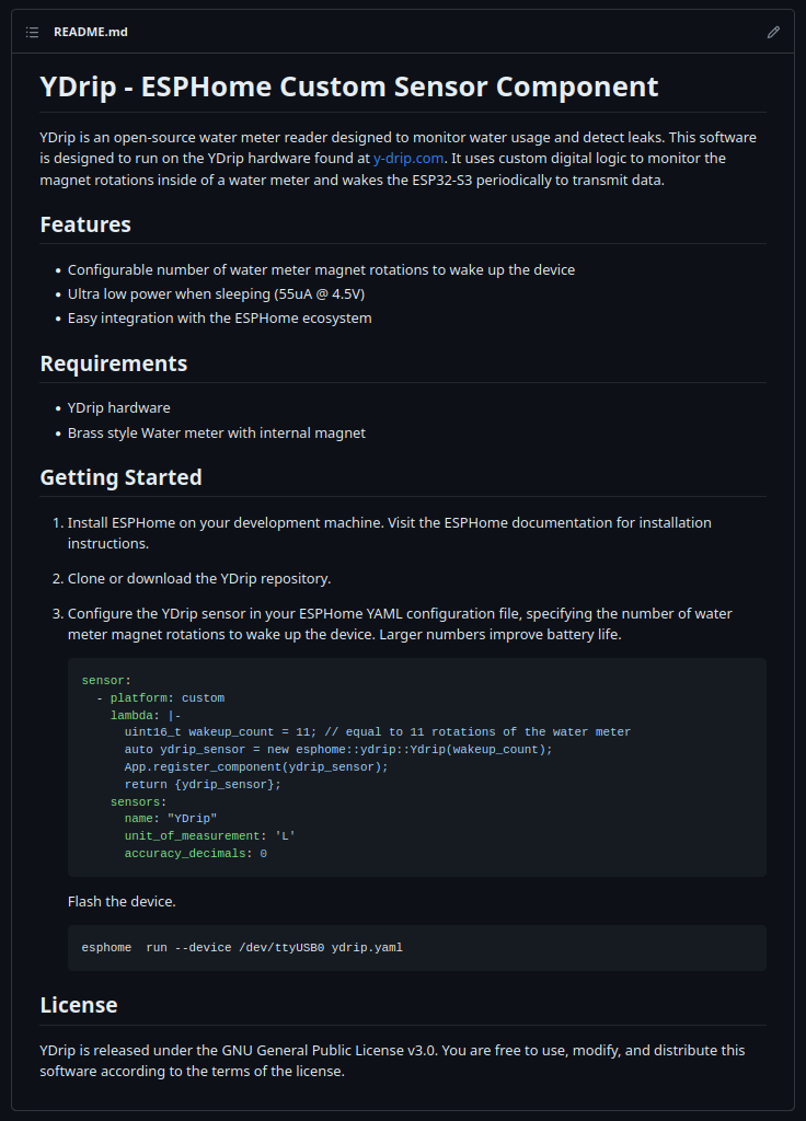
The first measurement shows the current draw (at 4.5V) while the ESP32 wakes up from sleep and transmits the water usage. Average current is 110mA over 6 seconds with fast connect enabled. This is fairly high and will limit how many times the device can update the server, but this is expected. There is lots of room to optimize here.
---------- more ----------![]()
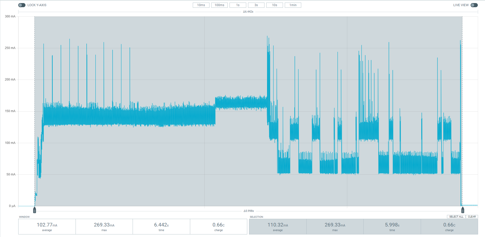
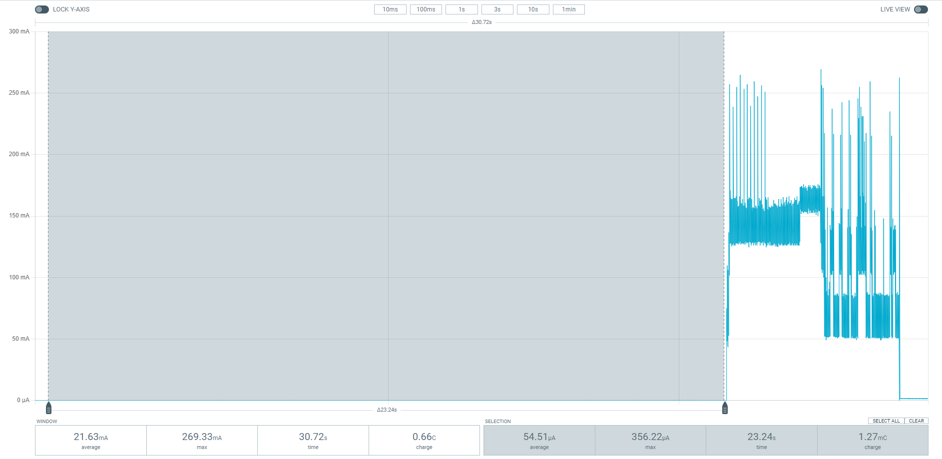
Next is a plot of the current draw while sleeping over an arbitrary length of time. Only 55uA! This is great considering YDrip is able to count magnet revolutions in this state. This value includes the ESP32 deep sleep current, 3.3v regulator quiescent current, magnetometer current and everything else. The main reason for the low current is due to the custom digital logic circuit that is duty cycling the magnetometer. A general purpose CPU would draw much more current to do the same task, which is why I chose not to use the Ultra Low Processor in the ESP32. It draw about ~300uA. I'll go into more detail on the design in a later post.Plugging these numbers into this great online battery life calculator give an estimated life of 880 days or 2.4 years. I assumed a transmit time of 30 seconds per day, which is about 5 transmissions per day. This does not affect how fast a user is notified of a leak and only reduces how real-time the water usage is.
The website author does nifty things like take the discharge curve of AA batteries into account, but real life is always more complicated. Still we're on a good track.
-
ESPHome and Home Assistant Integrations
06/24/2023 at 19:56 • 0 commentsDemonstration of ESPHome and Home Assistant integration.
-
Water Meter Test Setup
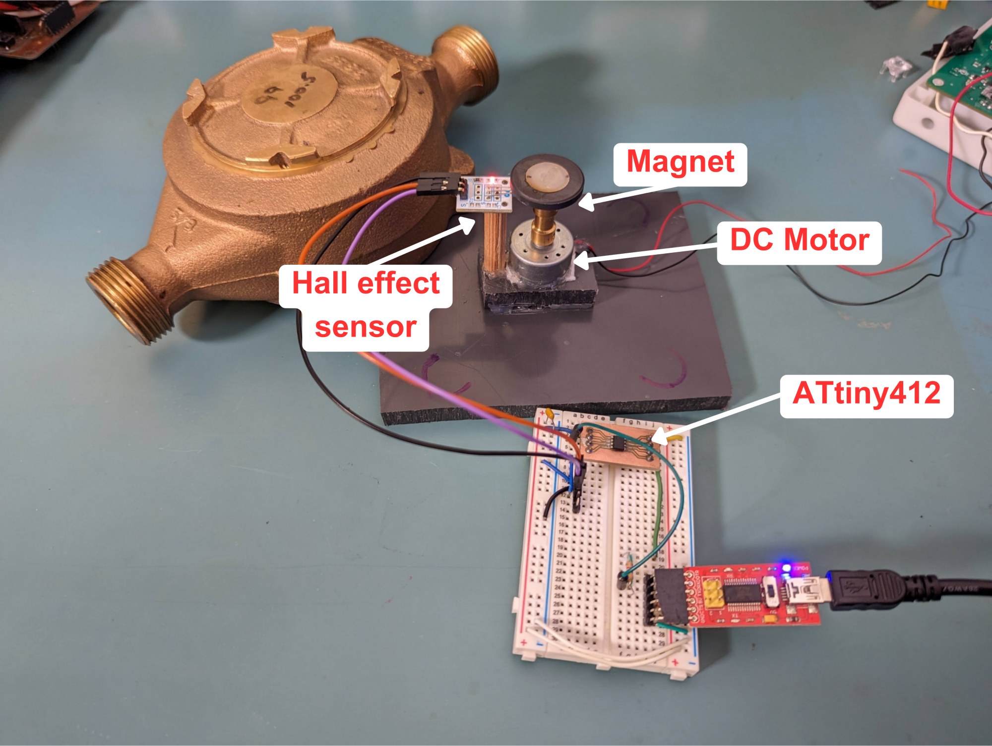
06/23/2023 at 22:54 • 0 comments![]()
This is the test jig I use for testing YDrip when I need to play with different variables like rotation speed, mounting angle and distance. It consists of a dissembled water meter magnet attached to a DC motor. The brass housing sits on top of both to simulate a real instillation. The The ATtiny412 counts the revolutions using a hall effect sensor and acts as a source of truth.
-
V2 Prototype - Battery Powered
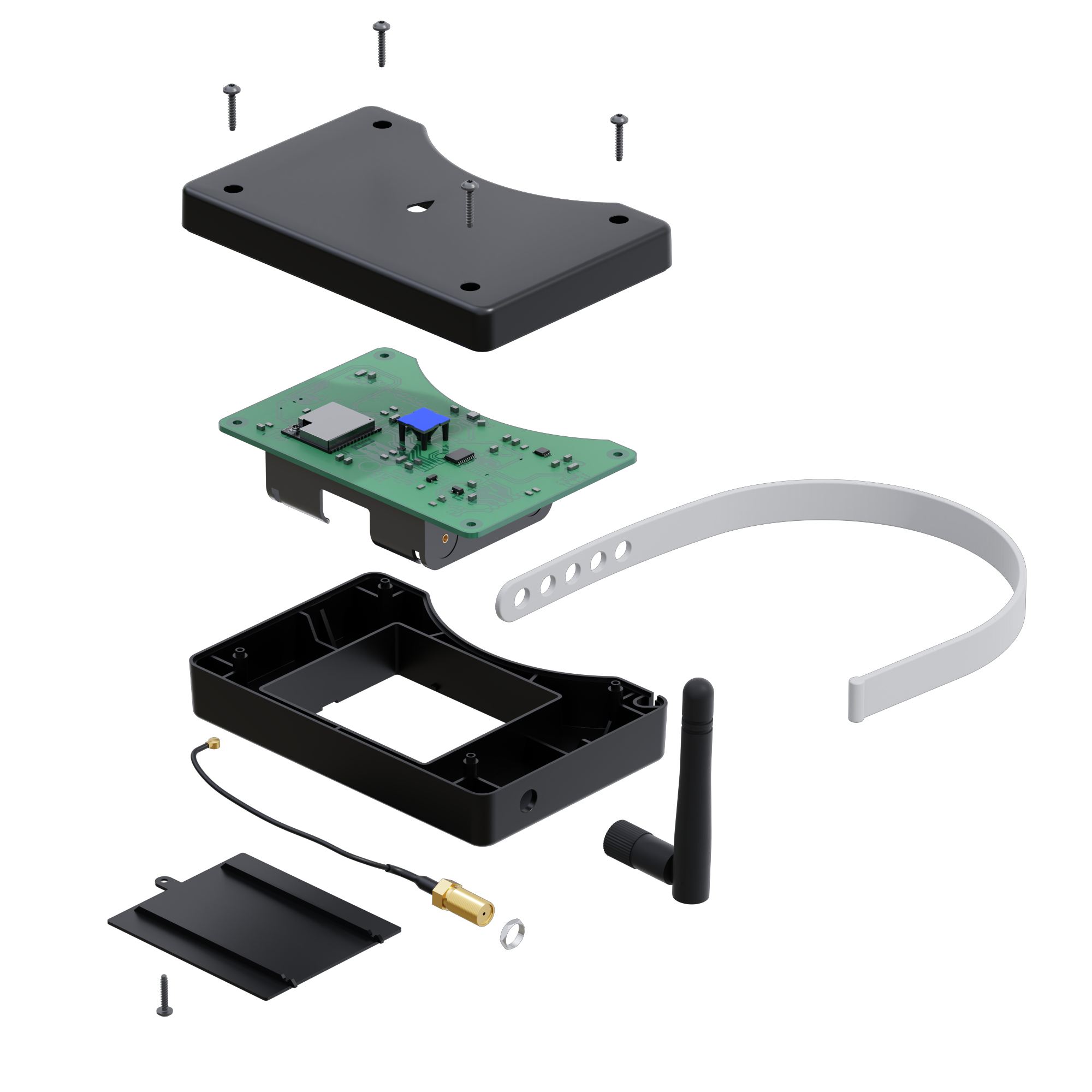
06/19/2023 at 19:12 • 0 comments![]()
The main goal for V2 was making it battery powered which turned out to be extremely difficult. First, the PCB and case was expanded to make room for three AA batteries.
Then I started replacing/adding a few components:- RT9080-33GJ5 regulator due to its low quiescent current.
- PCF8563 RTC as a low power clock source for the circuit and time keeping while the ESP is sleeping.
- ESP32-S3 replaced the discontinued S2 module
- RGB LED + lens for user feedback
- MB85RC64TA FRAM for storage
- ALT021-10E magnetometer
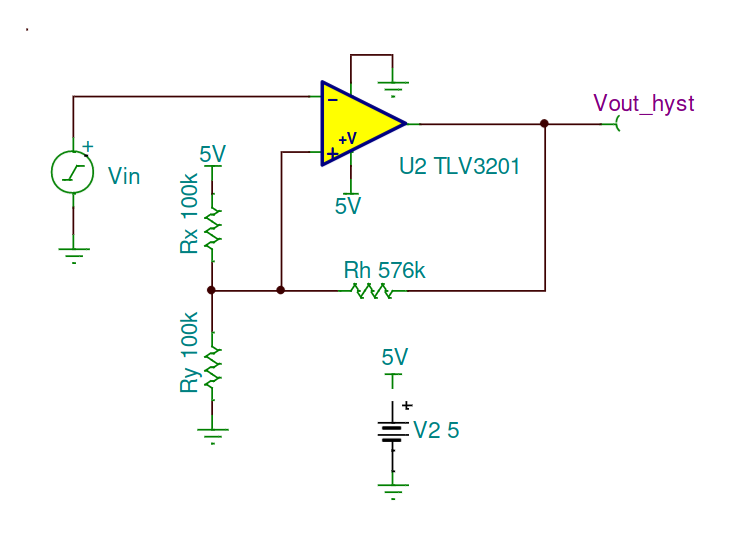
The major hurdle was finding a replacement for the LIS3MDL magnetic sensor. Having already exhausted my off the shelf sensor solutions I had to make something from scratch.---------- more ----------I started by designing a circuit using the DRV5055 hall effect sensor with an opamp and comparator to implement hysteresis. TI has a great document with some example schematics.
![]()
![]()
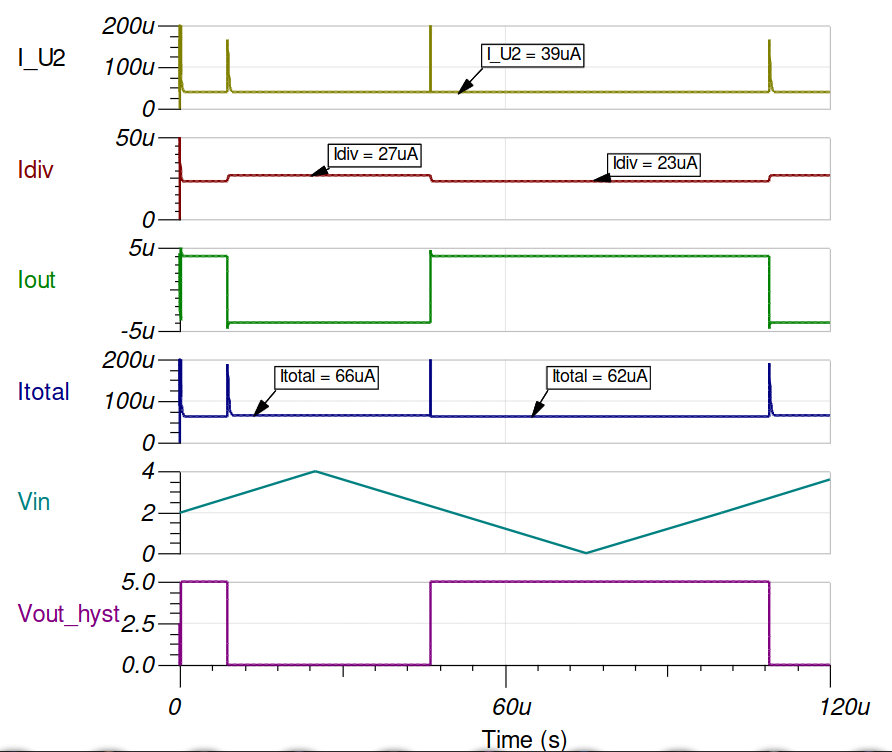
The current consumption isn't too bad at 10s of uA, but it's starting to add up.![]()
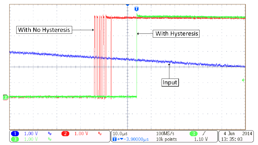
Here is an example of why you need hysteresis when counting zero crossings in an analog analog. The noise in the blue line causes the threshold to get triggered multiple times (red)
The DRV5055 consumes 10s of mA which is far too much so it's power needed to be duty cycled periodically. This would require a low power oscillator and transistor. At this point the bill of materials and circuit complexity was getting larger than I liked so I looked for another solution.
I settled on the SLG46826 by Renesas. It is a programmable mixed signal matrix. Similar to an FPGA, except much simpler in capabilities. It's designed to replace digital glue logic to save power and board space. In this case, I was able to replace the comparator, duty cycle and interrupt generation circuit with it.
That's where the state of the project is today. I realized this platform can be used as a generic data logging device for all types of sensors (e.g. power, gas, etc) so that's what I'll work on for V3. The major requirement missing for this is making the case waterproof.
-
V1 Prototype
06/19/2023 at 18:10 • 0 comments![]()
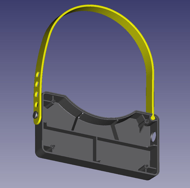
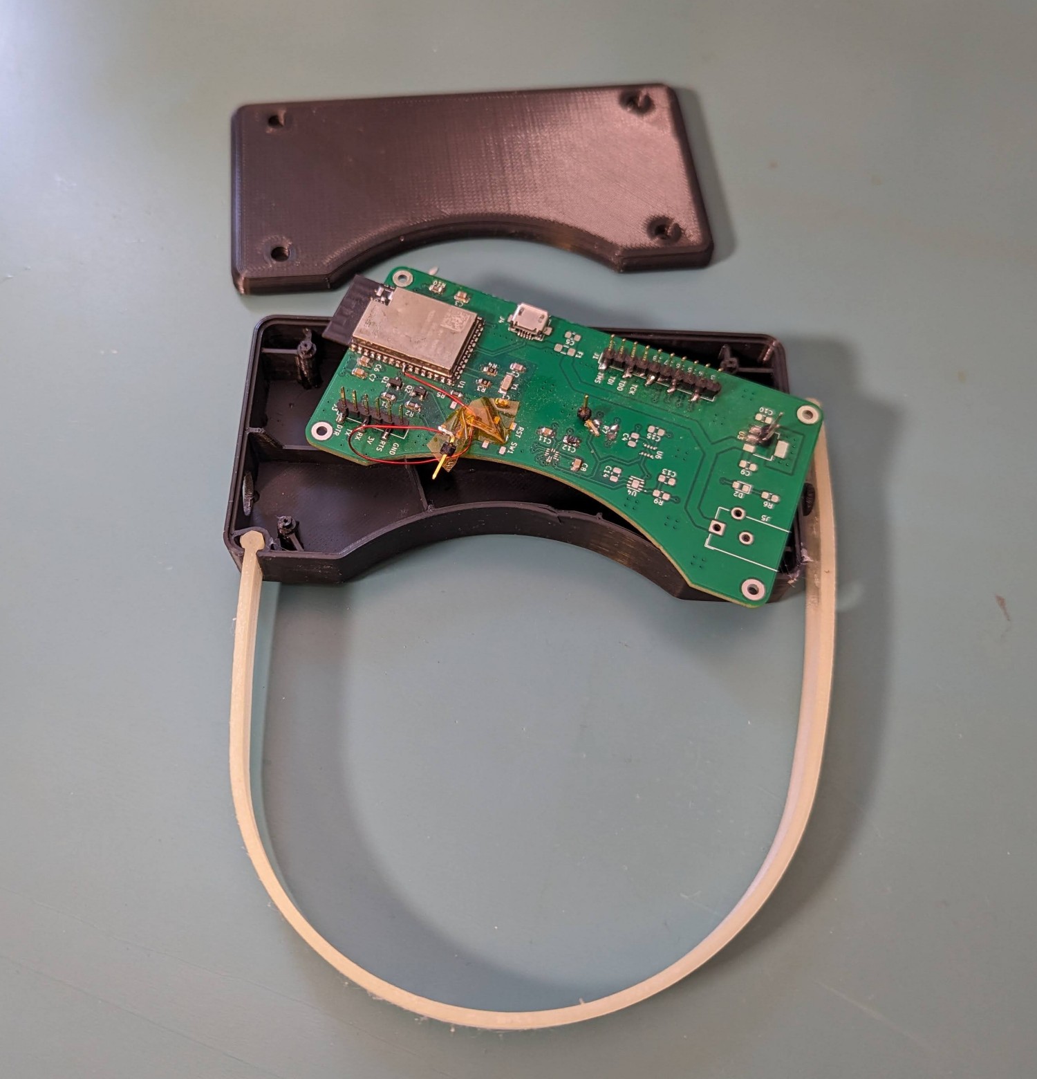
The V1 prototype attempted to neatly package up the V0 prototype. I 3D printed a case out of ABS plastic to mount it to the water meter. The strap was printed using TPU which is a flexible material.
---------- more ----------![]()
I switched to the more capable ESP32-S2 to allow me to remove the Arduino and combine all of the processing on one chip. It also allows OTA updates using ESPHome. Otherwise, the functionality was basically the same as V0. The only inconvenience with this version was the power. cable Water meters are usually installed in hard to reach areas of the house and don't always have an outlet near-by so I decided to look into making this battery powered.
There are a few problems with the current design to make it battery powered. Doing hysteresis in software uses a lot of power because of the continual sampling. The ESP32 modules have a ultra low power processor (ULP) which use ~200-300 uA when running. The LIS3MDL datasheet lists a current consumption of 40uA at 20Hz in low power mode. The power consumption goes up drastically from there once you increase the data rate. When you add it all up, I was getting close to 1mA which is too much for a battery powered device.
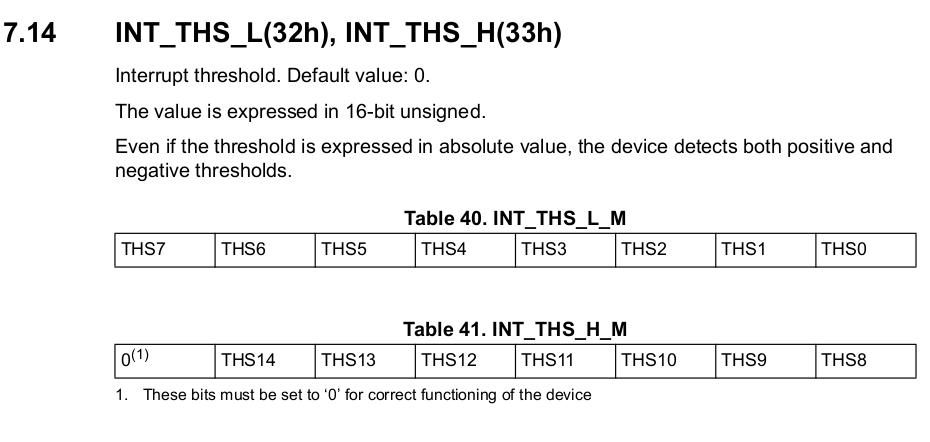
The LIS3MDL has a feature which sends interrupts above and below a threshold, but it doesn't let you set the positive and negative thresholds independently, which is required for hysteresis.
![]()
I started designing V2 after the limitations of V1 were understood. -
V0 Prototype - How a waters meter work and how to build a reader
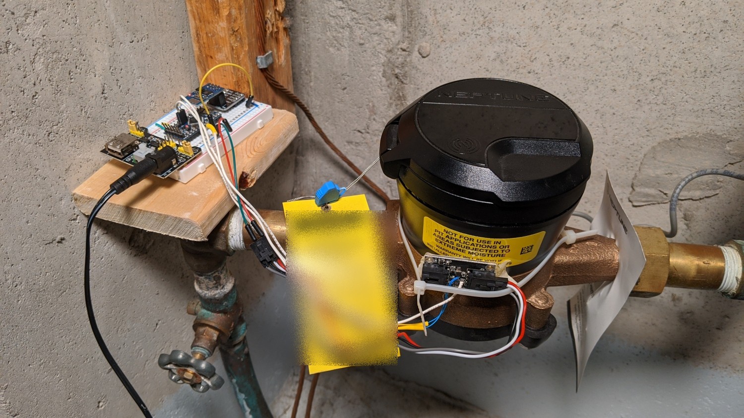
06/19/2023 at 15:43 • 0 commentsThis is the first version of the water meter reader I created after flushing hundreds of dollars down the drain due to a bad toilet. My city water meter apparently had a leak detection feature, but it didn't trigger and even if it did, I would see it since it only notifies you with a blinking LED. (My meter is in the basement). This was also around the time I started using Home Assistant and wanted a native device that didn't rely on 3rd party APIs to retrieve the data. The first step was understanding how a water meter works.
---------- more ----------How A Water Meter Works
There are two main parts to a water meter: The first is the brass housing with a mechanical flow meter that rotates a magnet. I'll call this the water meter. The second is a mechanical or electrical reader that measures the number of rotations. I'll call this the water meter reader. The water meter reader that your city installs sits on top of the meter so it's closest to the magnet inside. Here is a good animation of how this all works at 45 seconds.
V0 Prototype
![]()
The first prototype used an ESP8266, an Arduino mini and a LIS3MDL magnetic sensor (zip tied under the yellow sticker in the image above). The magnetic sensors in the video above do all of the hard work by converting the analog output of the varying magnetic field, which looks like a sine wave, into neat pulses a microcontroller can read. Each pulse or sine wave cycle corresponds to a rotation of the magnet (this depends on the number of polls it has), which gives you the volume of water through the pipe. Unfortunately, most are designed to sit a few millimeters away from the magnet and that spot is taken by the city reader so I had to mount mine on the side. I tried over a dozen parts from Mouser/Digikey, but couldn't find anything sensitive enough so that left a few options.
- Get a raw analog magnetic sensor and build a circuit to amplify the output and add hysteresis.
- Use a sensitive digital magnetic compass with built in amplification and do hysteresis in software.
I went with #2 for simplicity of hardware.
The simplest way to count sine wave cycles is a zero crossing detector. Hysteresis is utilized to mitigate false triggering caused by signal noise near the zero-crossing threshold. TI does a better job of explaining it here with pictures. The same principles apply in hardware or software.
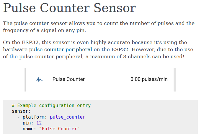
The Arduino would toggle a GPIO for each magnet rotation to the ESP which would transmit it to Home Assistant. I used ESPHome to create the firmware for the ESP. It's a 'no code' required platform that lets you define common functions in a YAML script. In this case I used their Pulse Sensor feature.
![]()
Everything was working well enough that I thought I would share it with the community as a kit, but I needed to make a few improvements.
- Simplify instillation: Mounting the magnetic sensor improperly could result in a different sine wave DC offset. I could solve this in software and/or improve the mounting mechanism.
- Make a PCB to avoid the rats nets of wires.