ydrip
ydrip-
Hackaday Prize 2023: Green Hacks Recap
10/10/2023 at 07:15 • 0 comments![]()
![]()
![]()
I wanted to provide a recap of the work done since being selected as a finalist for the Green Hacks contest. Here are the highlights:
- Multiple revisions of the enclosure and circuit after testing
- Redesigned the analog front end with auto DC offset calibration to reduce interference from the earth's magnetic field
- Added amplification to the magnetic sensor output
- Implemented a leak detection circuit using digital logic that doesn't require the CPU allowing ultra long battery life
- Demonstrated passive gas meter reading by measuring small changes in the earths magnetic field caused by moving metal inside of the meter
- Demonstrated smart meter electricity reading
- Performed power measurements using the ESP32-C6 and WiFi 6, which will improve battery life and responsiveness once integrated into the software
Why is it unique?
This project was designed to solve the narrow issue of water leaks, but the resulting design has shown to be much more broad. The reconfigurable digital hardware provides a lot of flexibility for more ultra low power sensors applications some of which have been demonstrated.
YDrip is a unique solution in many ways. First, passive gas meter reading is a totally unique use case with no commercial products on the market. Additionally. it has the capability to be a three in one device measuring all of the utilities.
Next Steps
Polishing up the software, getting ESPHome certified, designing a water proof enclosure and fixing a few minor hardware issues.
Video Promo
-
Smart Meter Power Reading
10/09/2023 at 16:40 • 0 comments![]()
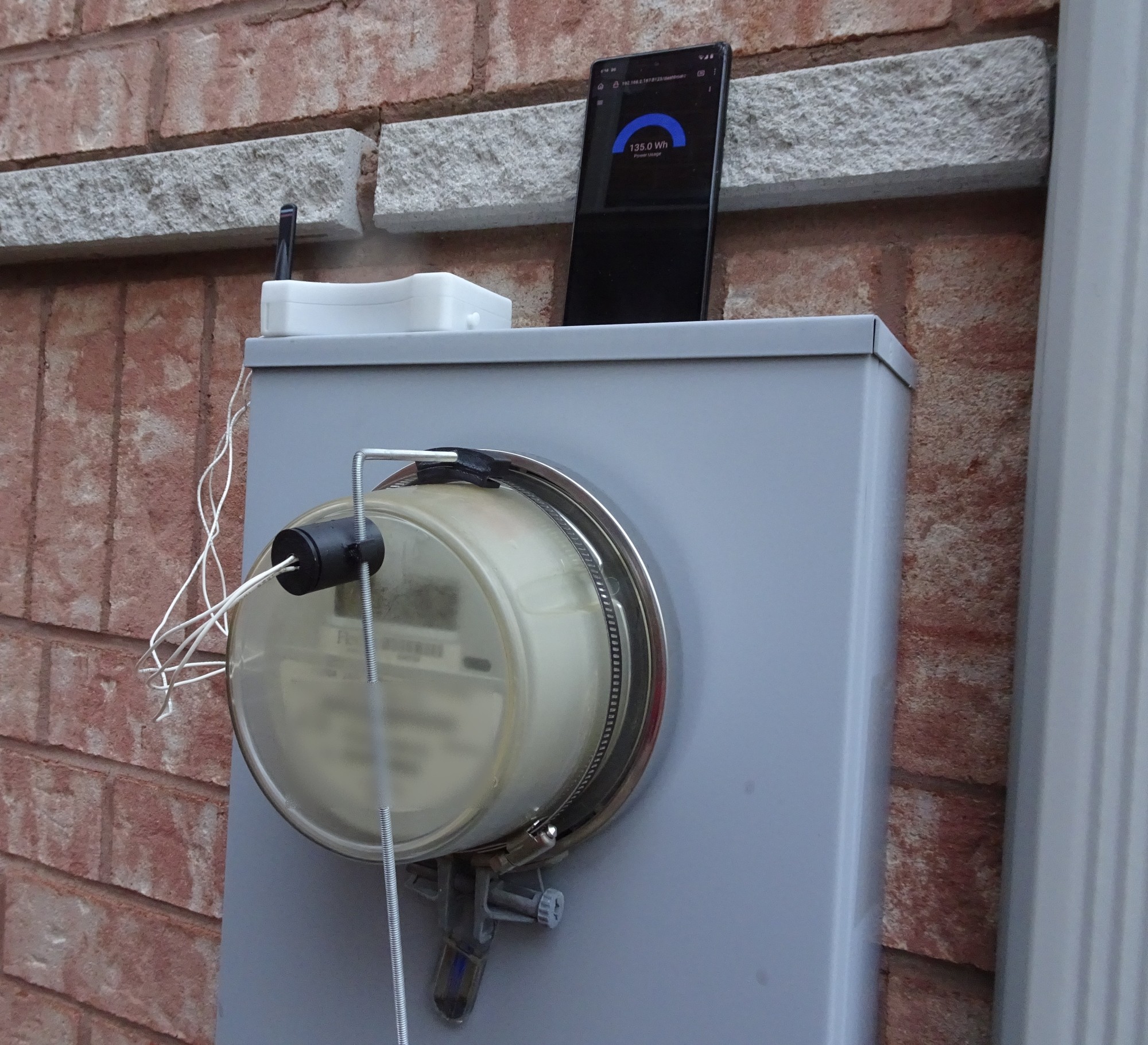
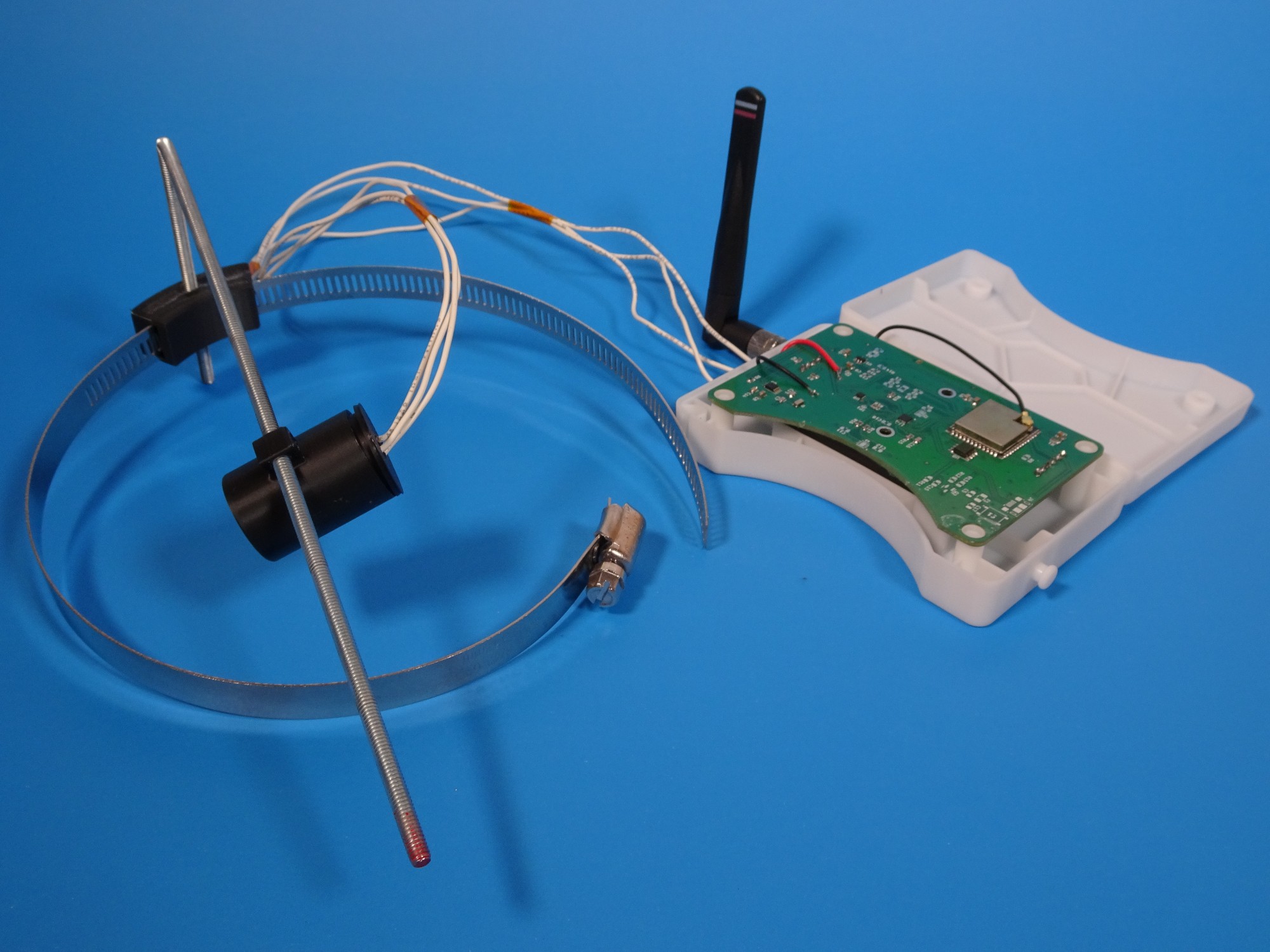
The ultra low power reconfigurable digital logic in YDrip makes it possible to log more than just water usage. The design is great for any application that needs to do simple logic like counting, leak detection or more. Smart meter reading is one of those applications. Most smart meters work by flashing an IR led to indicate electricity usage. You could use a general purpose CPU and wake-up on a GPIO interrupt, but this means the power hungry processor will wake up multiple times a minute draining battery. With YDrip, we can program the digital logic to count for us and wake the CPU when necessary. Using this approach we only use 60uA while reading.
![]()
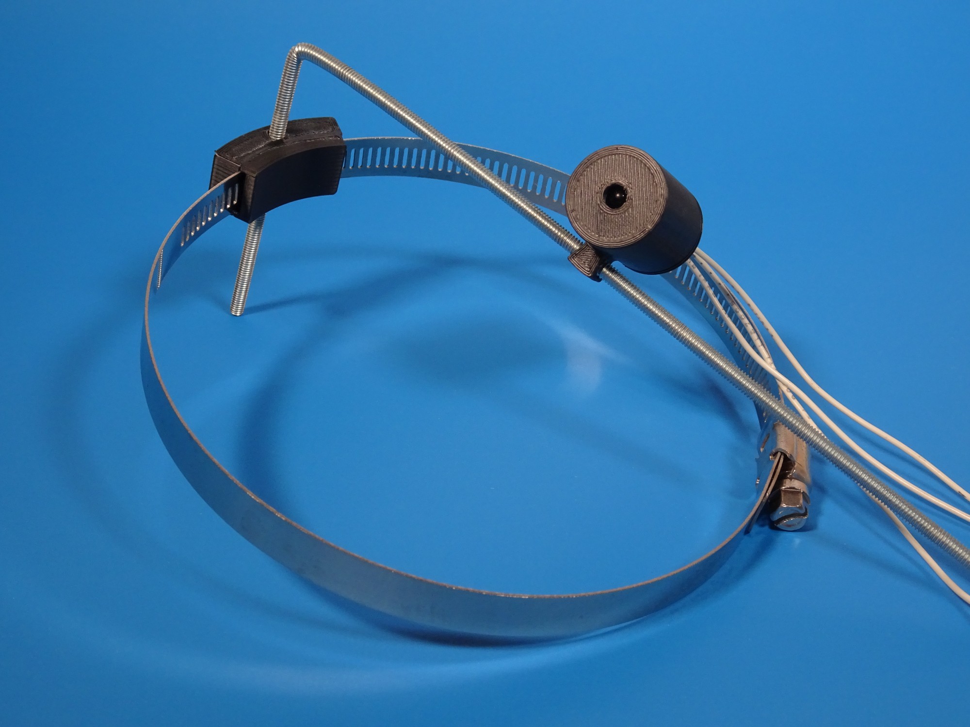
I 3D printed an LED housing and clamp holder for testing. In hindsight, using two claps to hold the threaded rode would provide more stability for the LED.
![]()
Three wires provide power, ground and signal from the YDrip expansion connector to the LED.
![]()
Here is the github branch I made for the software modifications:
-
Promising WiFi 6 Power Measurements with the ESP32-C6
10/07/2023 at 02:26 • 0 commentsTldr: YDrip V3 was designed to be footprint compatible with ESP32-C6, which supports WiFi 6. A key feature of WiFi 6 is the ability for devices to sleep for extended periods while remaining connected. This solves the issue of not being able to communicate with the ESP32 while it's in deep sleep.
Light Sleep
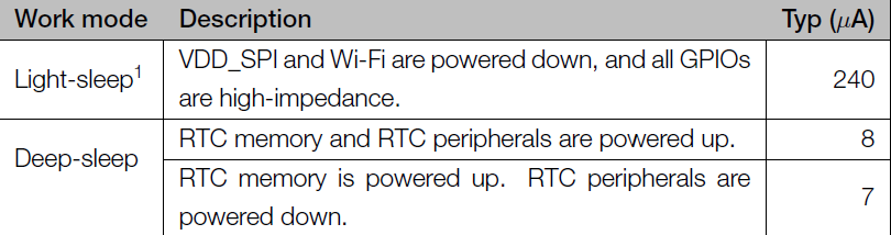
One of the misconceptions about the ESP32 is that they are capable of running on batteries for long periods of time. They are IoT devices after all right? Unfortunately, the details get complicated when you actually try building an application. Let's use the ESP32-S3 as an example:
![]()
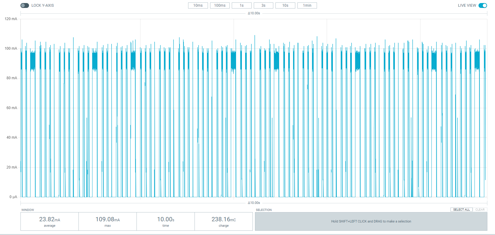
The datasheet specifies a range of 7 to 240 microamps depending on the sleep state. However, you quickly learn that light sleep is the only possible mode if you plan on using WiFi (which is the main feature of ESP32). This is because the ESP has no way of saving the WiFi association information in deep sleep. In light sleep, the CPU powers down some components until the next beacon from the access point (100s of milliseconds). Here is an example of the C6 in light sleep mode.
![]()
You can see the ESP32 wakes up many times to stay associated with the AP and uses an average of 23mA. This is better than the 100 mA you can expect without light sleep, but this is not low enough to be battery powered for months.
Deep Sleep
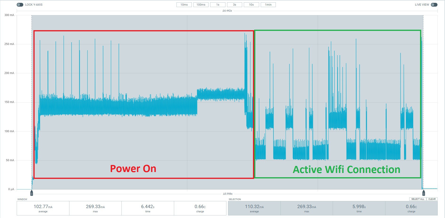
The other approach, which is what I chose for YDrip, is to go into deep sleep until you have data to report back and re-associate every time. There are two trade offs here. The first is boot and WiFi association uses a lot of power. Here is an example from an earlier measurement I took with V2.
![]()
The ESP uses more than 150mA during boot for a few seconds. The total power consumption after establishments a connection is 100mA, but is highly dependent on how long the negotiation takes. The second down is you can't communicate with the device in deep sleep until it wakes. Not a great user experience if they need to change settings for example.
WiFi 6 Solution
Luckily, this isn't a problem that only affects the ESP32, which is why the WiFi Alliance has made some changes to the latest standard. Like I mentioned above, earlier versions of WiFi required devices to go into light sleep between beacons every few hundred milliseconds. WiFi 6 introduce the concept of Target Wake Time (TWT), which allows devices and access points to negotiate this sleep time instead. This means YDrip can sleep for extended periods of there is no water usage while still remaining connected.
V3 is footprint compatible with the ESP32-C6 so I decided to get a TP Link AX180 WiFi 6 router and test it out. Support of C6 in ESPHome is still a work in progress so I used the itwt example from the ESP-IDF. These are the settings I used to configure TWT.
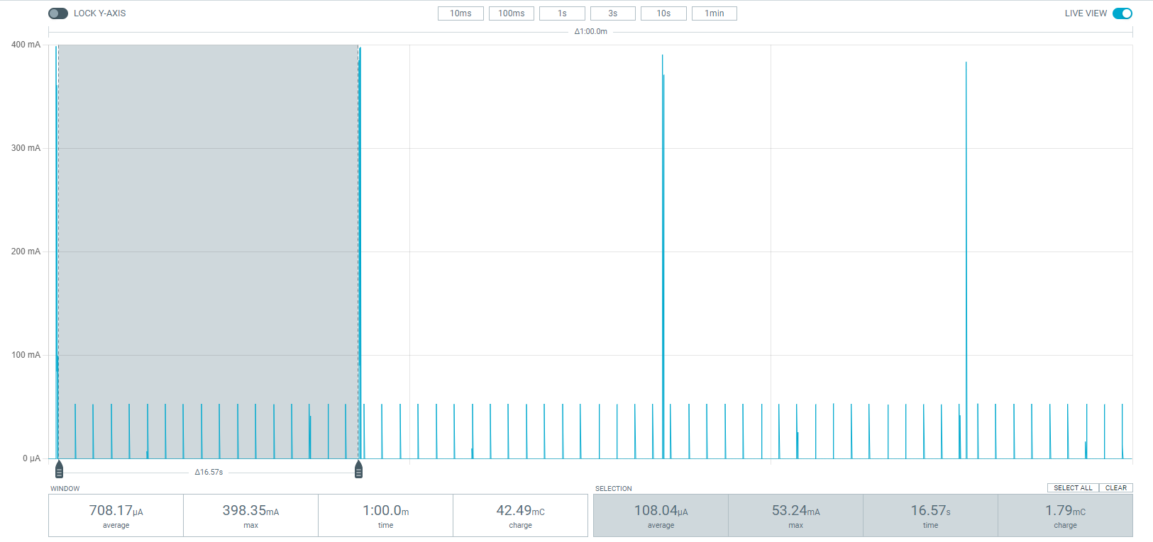
/* setup a trigger-based announce individual TWT agreement. */ wifi_phy_mode_t phymode; wifi_config_t sta_cfg = { 0, }; esp_wifi_get_config(WIFI_IF_STA, &sta_cfg); esp_wifi_sta_get_negotiated_phymode(&phymode); if (phymode == WIFI_PHY_MODE_HE20) { esp_err_t err = ESP_OK; wifi_twt_setup_config_t setup_config = { .setup_cmd = TWT_REQUEST, .flow_id = 0, .twt_id = CONFIG_EXAMPLE_ITWT_ID, .flow_type = flow_type_announced ? 0 : 1, .min_wake_dura = 255, .wake_duration_unit = 0, .wake_invl_expn = 10, .wake_invl_mant = 16384, .trigger = trigger_enabled, .timeout_time_ms = CONFIG_EXAMPLE_ITWT_SETUP_TIMEOUT_TIME_MS, }; err = esp_wifi_sta_itwt_setup(&setup_config); if (err != ESP_OK) { ESP_LOGE(TAG, "itwt setup failed, err:0x%x", err); } } else { ESP_LOGE(TAG, "Must be in 11ax mode to support itwt"); }![]()
The plot above shows the device wakes up every 16 seconds and uses an average of 708uA while staying associated. This is a dramatic improvement over the 23mA we saw with light sleep. While it's not as low as the 50-100uA if we deep sleep until some water usage is detected, it's a great trade-off for users that want communicate with the device.
-
Water and Gas Meter Reading Demo + New Issues
09/27/2023 at 18:30 • 0 commentsQuick update on the status of V3 testing. Water and gas meter reading works. DC offset calibration is working well. The only new issue is the metallic housing on the AA batteries is causing significant interference with the mag sensor. Enough that it saturates the sensor beyond the offset calibration capabilities. I will either need to redesign the PCB and case to add more distance between them or switch to a different battery technology.
-
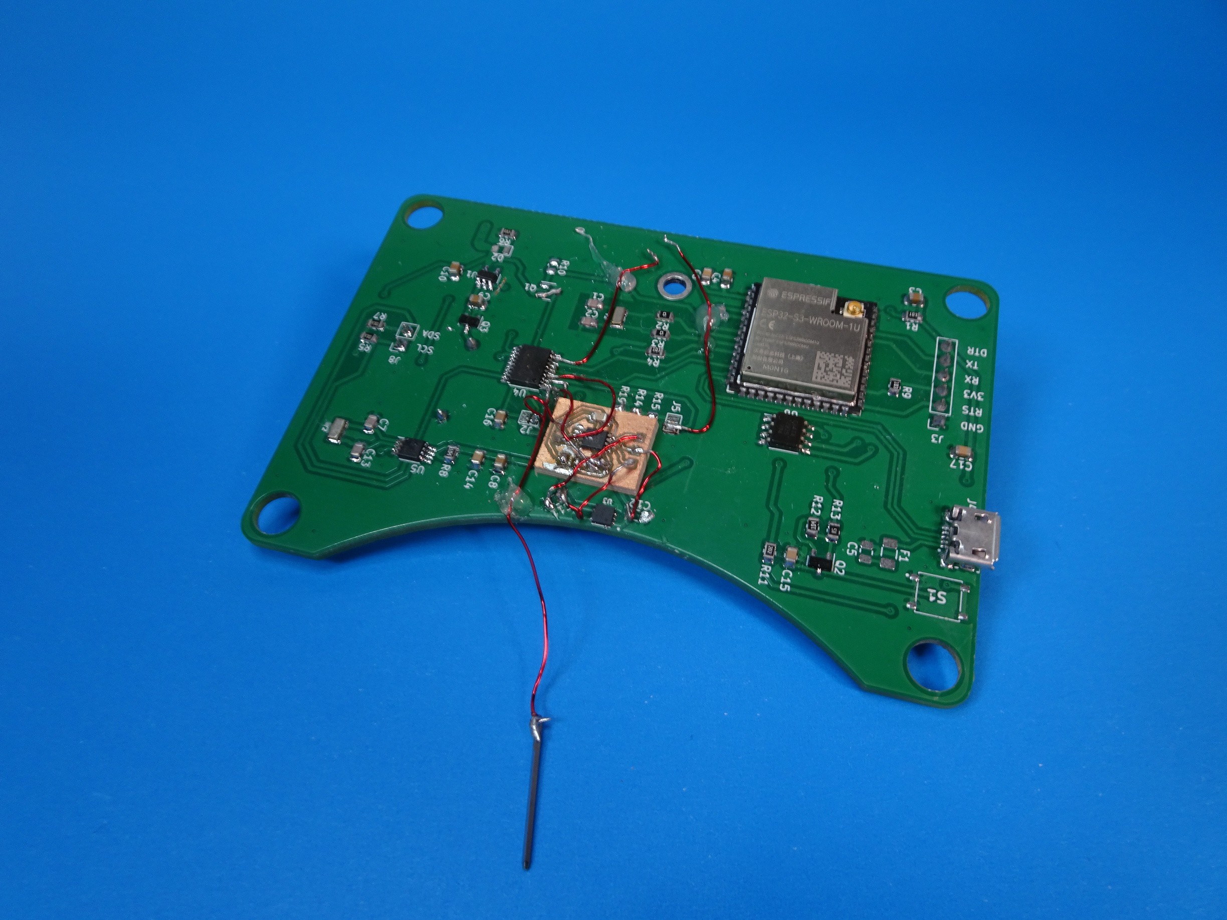
V3 Prototype - New Analog Front End + Refinements
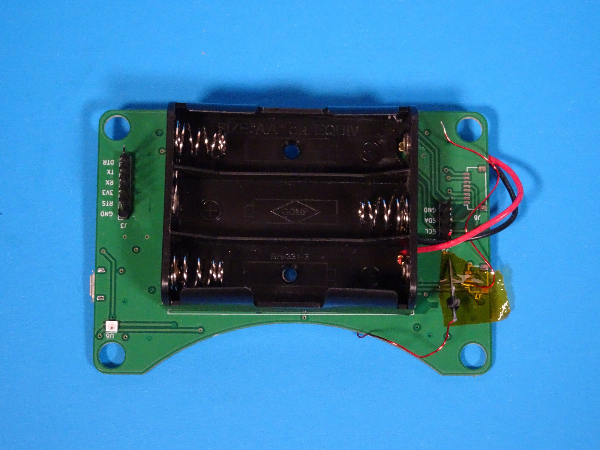
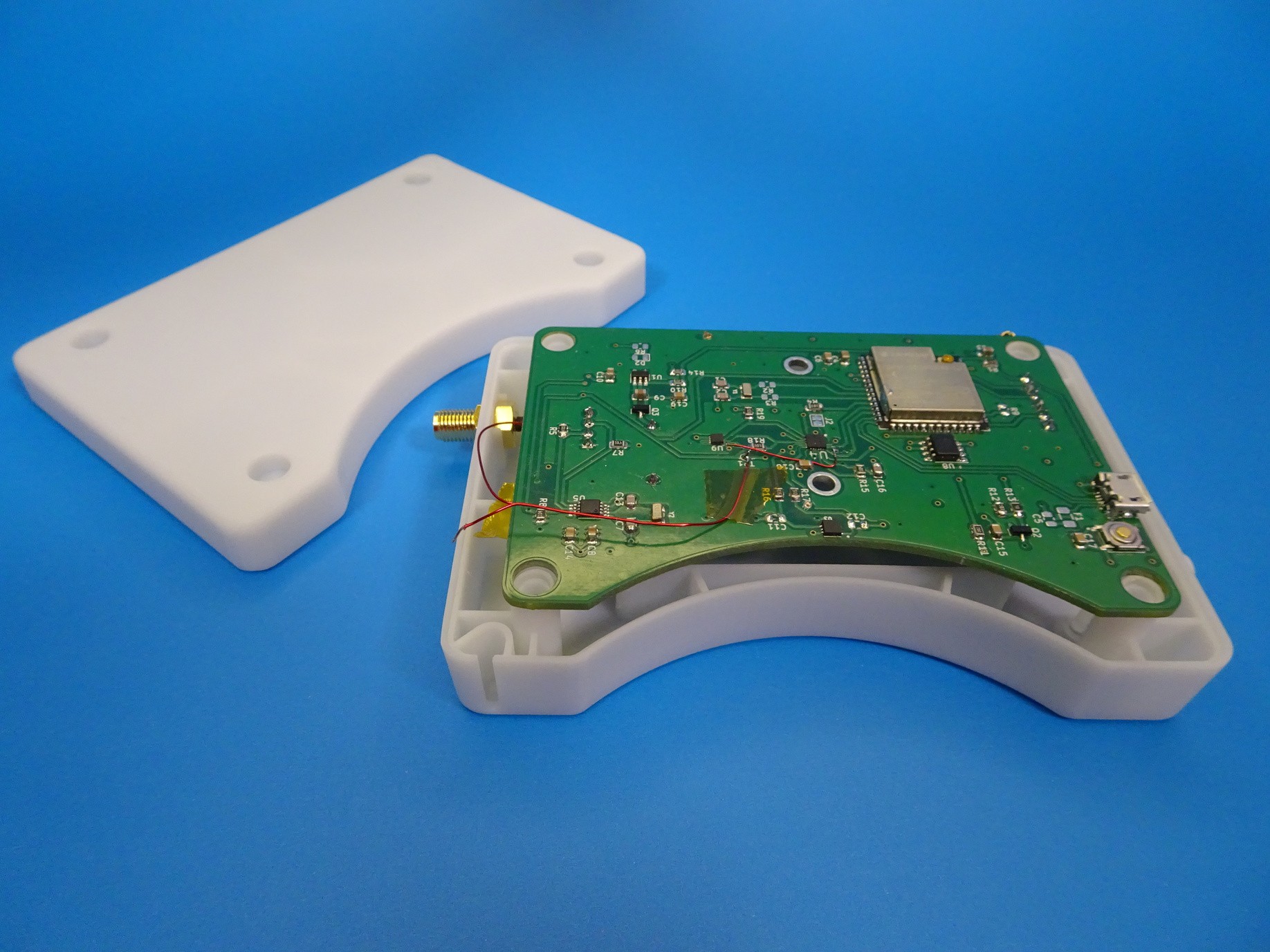
09/23/2023 at 18:35 • 0 commentsV3 (beta) of YDrip has been assembled and tested. The main goal of this version was to add dynamic gain and DC offset control. This makes the design able to measure gas meters and water meters with weak magnets from a larger distance.
![]() ---------- more ----------
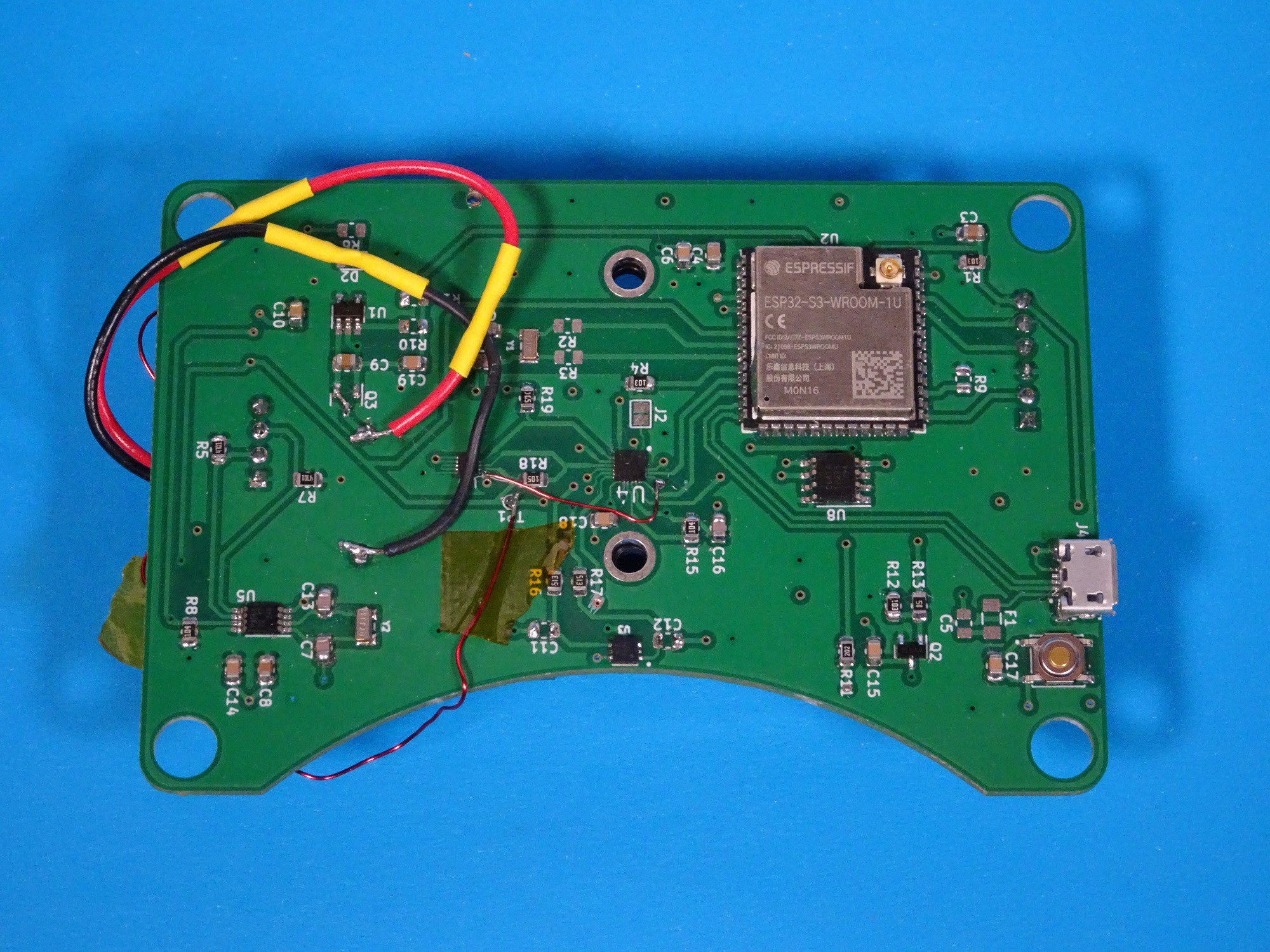
---------- more ----------Analog Front End
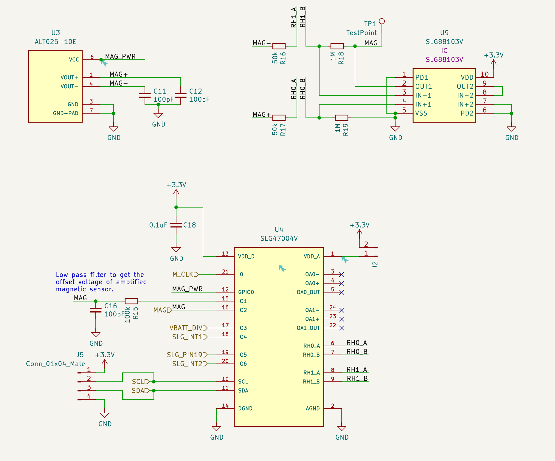
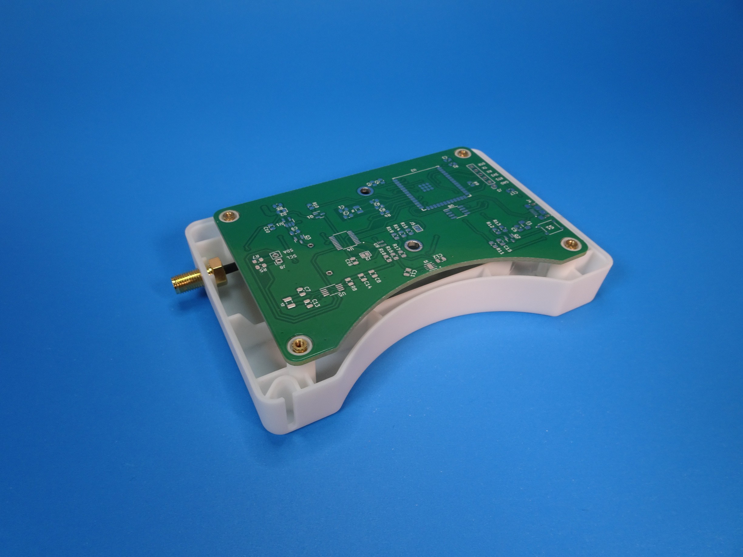
![]()
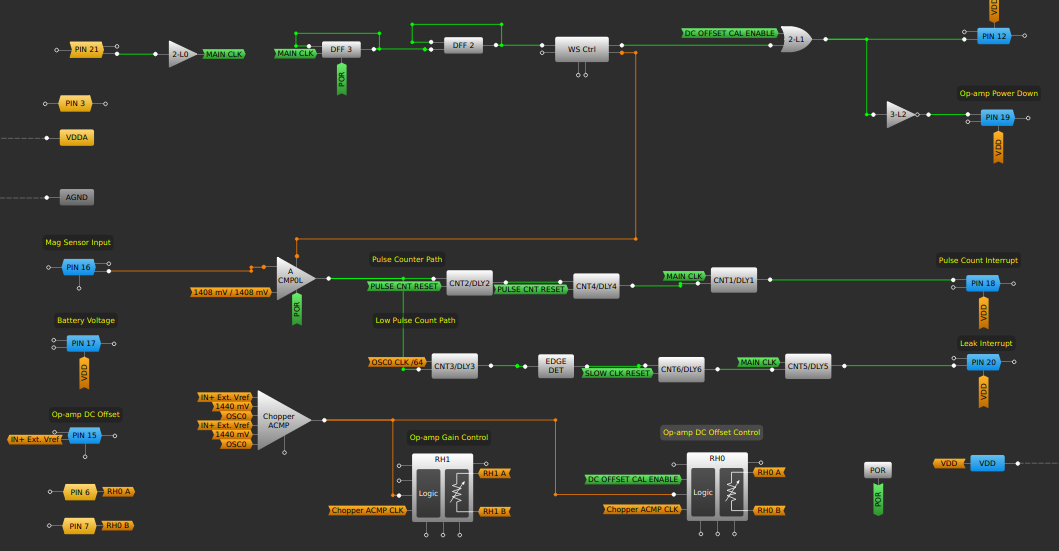
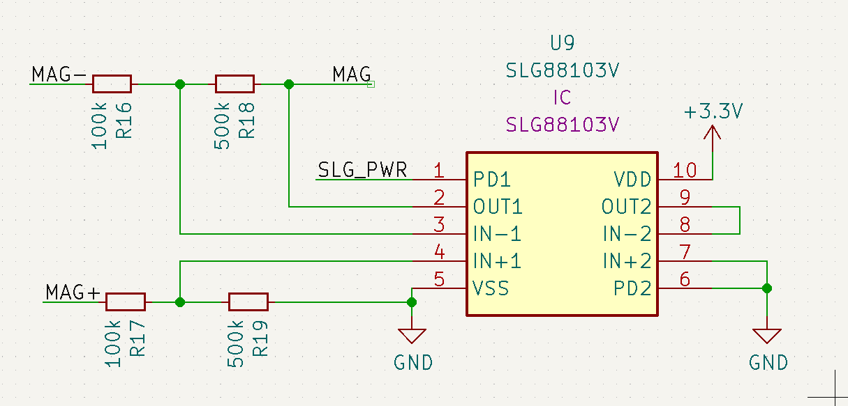
I have upgraded to the SLG47004V from the SLG46826 because it has more analog capabilities. Specifically, it includes opamps, rheostats and more analog comparators. The opamps don't have power down capabilities so I've decided to stick with the external SLG88103V for longer battery life. The digital logic design is basically the same except for the two rheostats at the bottom of the picture above.
![]()
The rheostats (pins RHx_[A/B]) act as the feedback resistors for the SLG88103V opamp. The SLG47004V has the capability to dynamically control the rheostats using the chopper analog comparator, which is only being used to control the DC offset at the moment.
Here is how it works. The DC offset of the amplified mag sensor output is measured using a low pass filter (pin 15 of the SLG47004V). The chopper analog comparator compares this voltage with a chosen reference. 1.4v in this case. The comparator then sends up/down signals to the rheostat until there is no difference between the two voltages. The rheostat is connected to the biasing resistors of the opamp.
Here is a video showing the difference with and without automatic DC offset control. The output amplified signal is no longer affected by the earth's magnetic field making is much easier to calculate zero crossings.
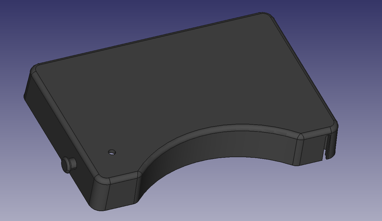
Enclosure
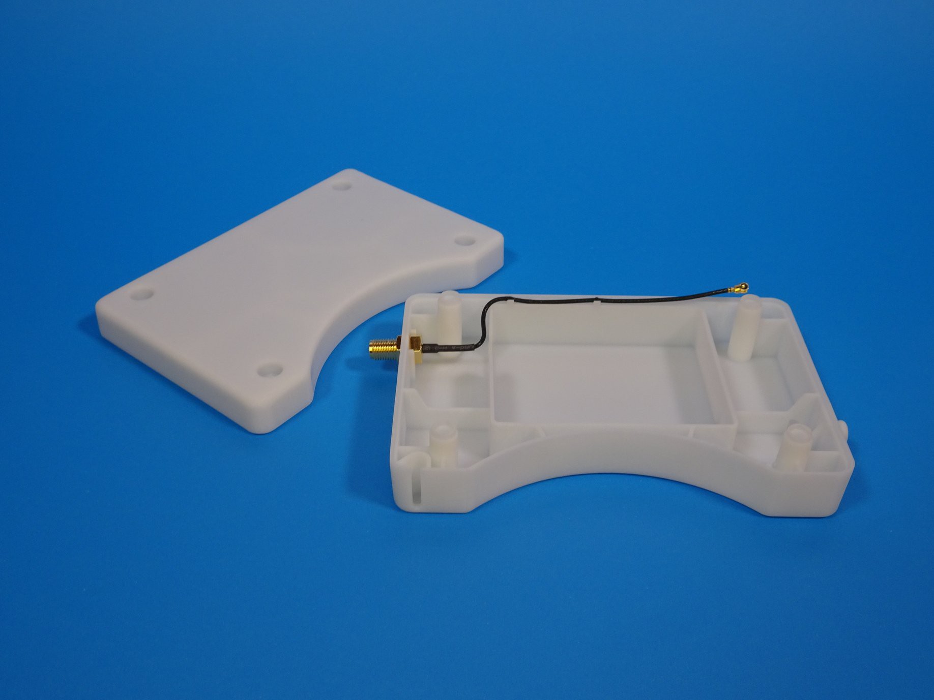
![]()
The enclosure design remains mostly the same with the exception of a change in the intended installation orientation. It is now meant to be installed upside down so the PCB is closer to the magnet in the water meter. This meant I needed to redesign the light guide since there was no room for the old one on the other side of the PCB due to the battery holder.
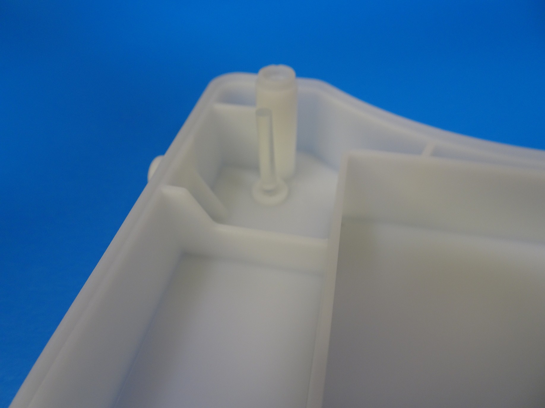
![]()
I went with a cylindrical design and placed the LED in the corner.
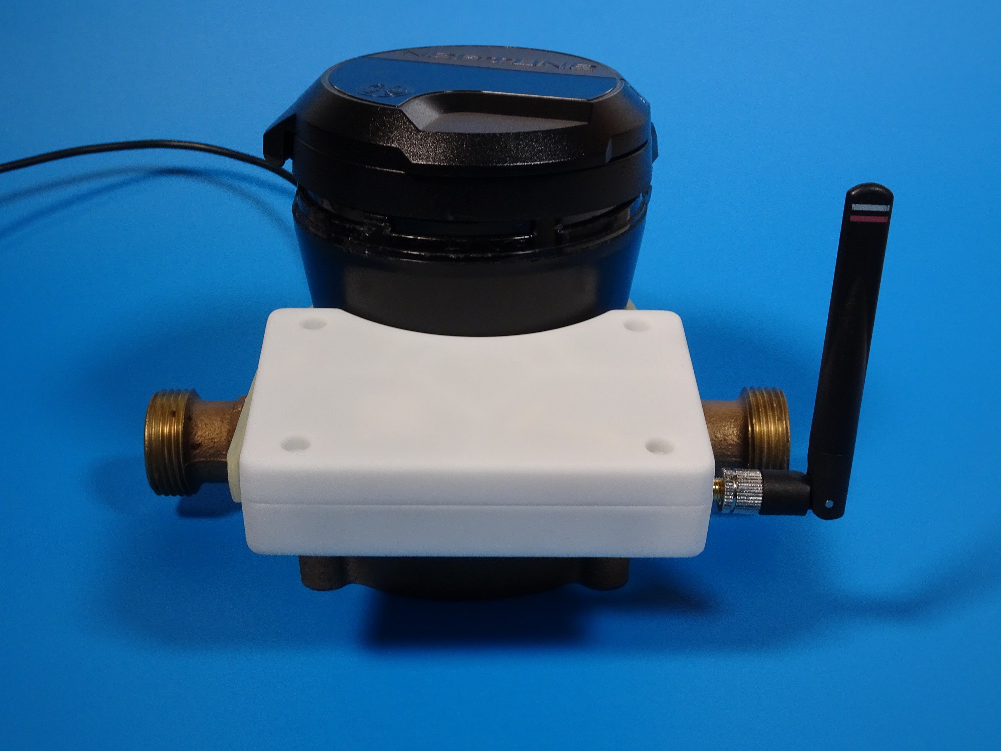
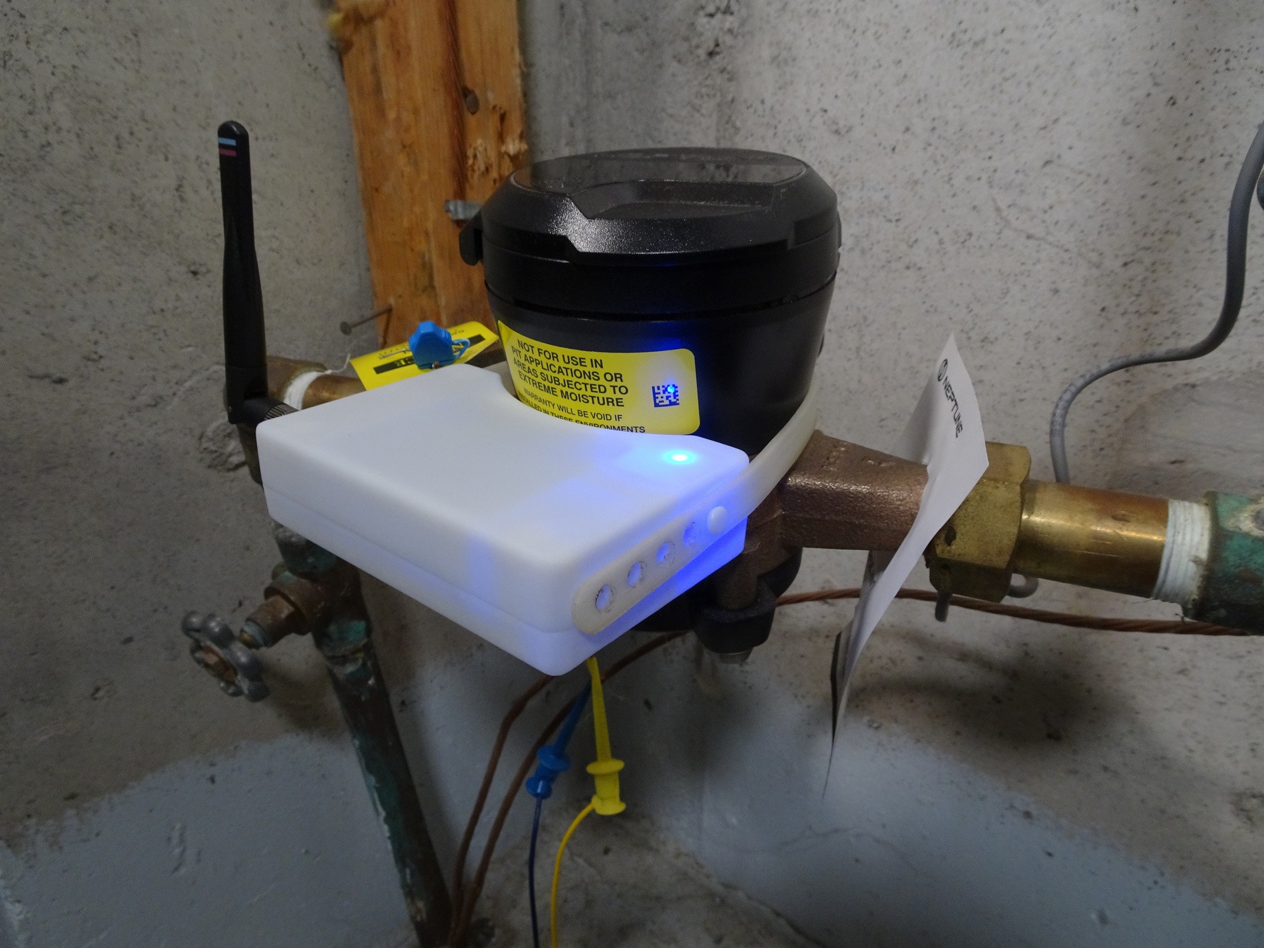
![]()
Here is what it looks like installed and running.
Other minor changes included: reduced the case rib size and a holder for SMA connector to make it easier to screw in.
-
Passive Gas Meter Reading
09/09/2023 at 21:08 • 0 commentsOne of the larger goals for this project is to build an ultra low power platform to measure a variety of sensors. The next logical step after water meters is measuring gas meters for a few reasons. There are no passive devices on the market that do this for 'dumb' mechanical meters as far as I know. Second, natural gas companies usually charge months after a home owners usage (similar to water), which can lead to surprise bills. However, gas meters work a bit differently than water meters, which presents new challenges.
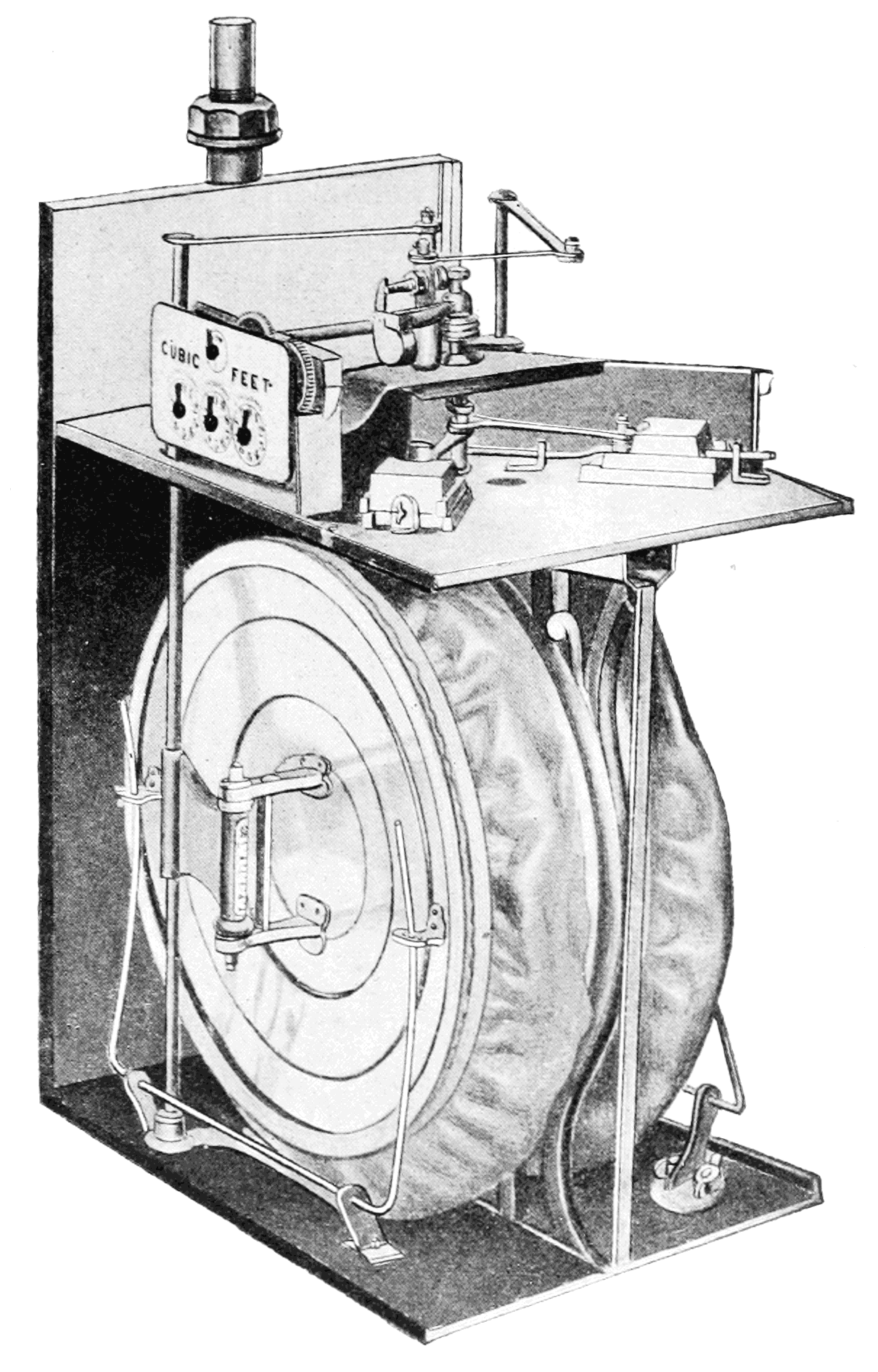
![]()
Source: Wikipedia
Basic mechanical gas meters use a diaphragm that expands and contracts with the flow of gas. This in turn moves levers and gears to eventually turn a mechanical dial indicating the usage. There are no magnets in this design so I decided to measure the change in the earth's magnetic field caused by the moving metallic parts instead.
In the previous two post I discussed how the earth's magnetic field was adding a variable DC offset depending on the orientation of the sensor. In this case, I'm using it to my advantage. I'll do a more detailed write up on how I modified the design to do this in the next post. For now, check out the video demo above.
-
Ultra Low Power Design with Mixed Signal Programmable Logic
08/31/2023 at 01:19 • 0 commentsThe most interesting aspect of YDrip is likely its programmable logic. This is where a lot of the heavy lifting happens, including tasks such as leak detection and revolution counting. While it's possible to use a low-power microcontroller as an alternative, the drawback is that it would significantly increase power consumption. This isn't ideal for a product designed to remain operational over many months. Some microcontrollers, like Atmel and TI's MSP, come with customizable hardware blocks capable of performing basic functions like hardware-based counting. However, their capabilities are somewhat limited. This is why I ultimately decided to opt for a complete hardware solution.
My initial approach was to use discrete logic chips until I found the GreenPAK product line from Renesas. Specifically, the SLG46826 model. It's reconfigurable, energy-efficient, and cost-effective ($1.60 for individual units). The package includes features such as analog comparators, counters, logic gates, oscillators, and more.
Analog to Digital
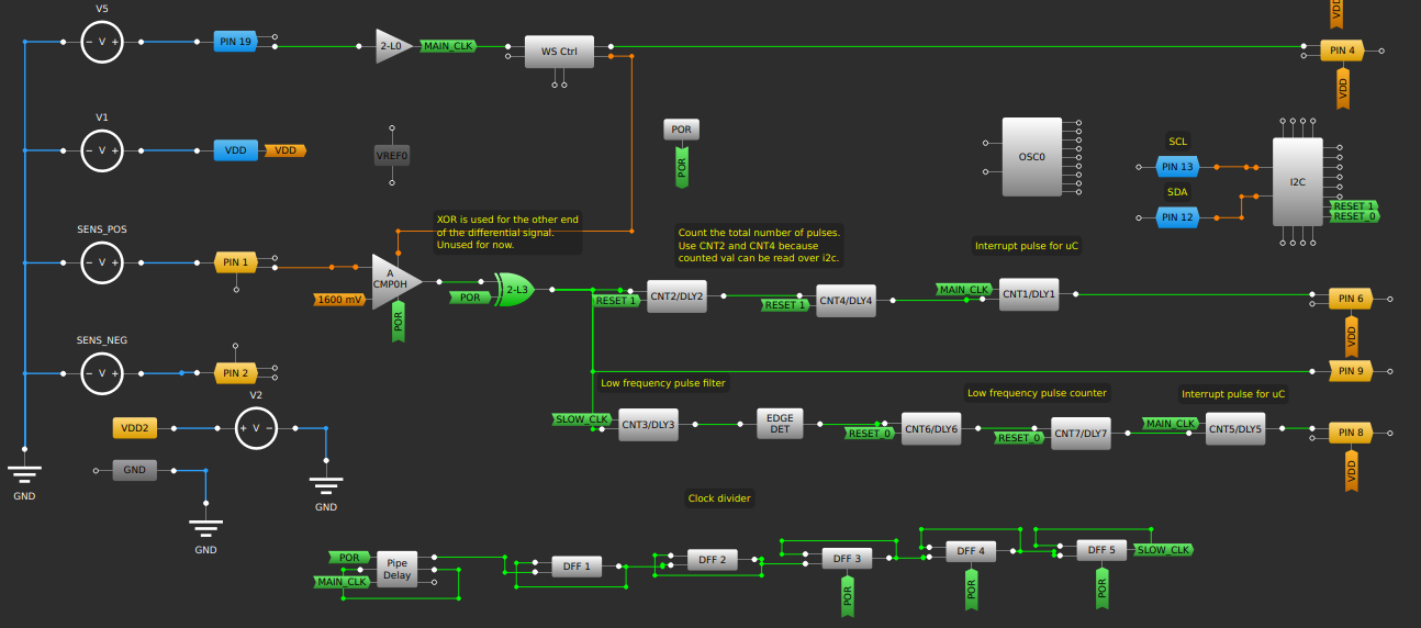
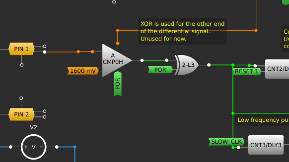
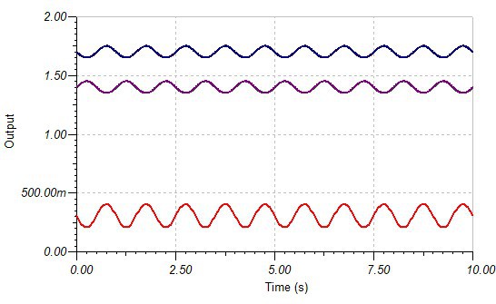
Starting from the left, the sine wave from the TMR sensor is fed into one input of the analog comparator. The other input is a reference voltage of 1600mV, which is the midpoint of the signal. Any voltage from 32mV to 2V can be selected in increments of 32mV. In earlier designs I used two comparators. One for each differential output of the TMR sensor and XOR'd them together. This provided no benefit so I removed the second one. Using a differential signal would help if the difference between them was amplified, but I was not doing that at this point. Here is an example of a differential signal:
![]()
The red signal is the difference between the two signals above it and is twice as large. This improves the signal to noise ration and shows why differential outputs are used.
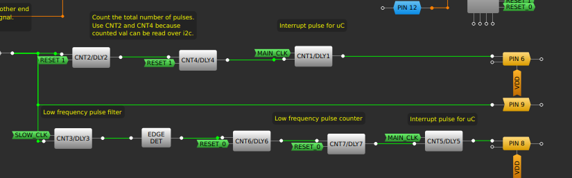
Pulse Counting and Leak Detection
The high/low output of the comparator splits into two paths. The top path measures the total water usage. It consists of two programmable 8 bit counters. When they overflow that triggers a third counter configured as a one shot counter to send a short wake-up pulse to the ESP32S3.
The bottom path is the small leak detection logic. It low pass filters and counts the pulses. This filter is configurable via I2C. That value gets stored in two 8 bit counters and another one shot counter is used to send a leak interrupt signal.Wake-Sleep Controller
A critical part of achieving a long battery life is duty cycling the magnetic sensor. It draws about 300uA. The wake-sleep controller can duty cycle power to the sensor and have the analog comparator only sample during 'on' times. This brings the system power down to only 55uA! See the previous post about power consumption. The main clock for the system is brought in from an external 32kHz RTC because the internal low power 2kHz oscillator is a little too slow.
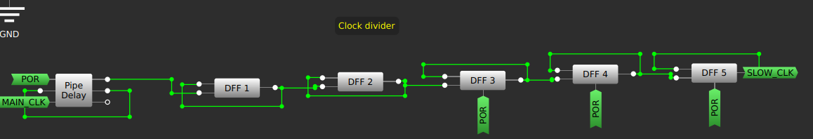
Clock Divider
Finally, a series of flip flops are used to divide down the 32khz clock to 64Hz. This slow clock is used to detect long running leaks by the low pass pulse filter.
Conclusions
By utilizing a mixed signal programmable logic IC this design was able to achieve a standby current of 55uA while also maintaining a variable wake-up time and leak threshold. Almost all of the logic blocks have been utilized in the SLG46826 making maximum use of it's capabilities.
-
V2.5 Prototype - Adding Mag Sensor Amplification
08/24/2023 at 19:35 • 0 commentsSponsor
This version of YDrip was kindly sponsored by PCBWay. They have been my PCB vendor for version 1 and 2 so I'm thrilled they decided to sponsor the manufacturing for v2.5. I've used them in the past because their website provides real-time updates with the status of your product and their support engineers provide great design feedback to make sure their are no manufacturing delays. The ordering process is also extremely easy with their KiCad plugin, which automatically packages your board design, opens a browser, and adds it to your shopping cart.
![]()
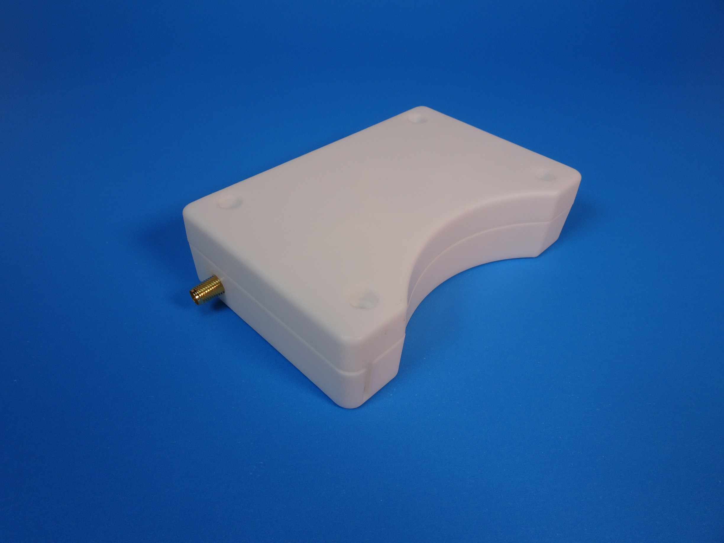
v2.5 prototype STL printed enclosure and PCB This was my first time ordering 3D printed STL parts from PCBWay and I'm very satisfied with the result. The 0.8mm lip that connects the two halves of the enclosure printed perfectly along with all of the ribs for rigidity. Their part finishing is also well done with no signs of support marks or warping. The PCB quality is what you've come to expect with no flaws and good enough dimensional accuracy to friction fit into the case. Thanks PCBWay.
![]()
Fully assembled enclosure Electronic Design Changes
The ALT021-10E is an ultra sensitive magnetic sensor (0-0.25 mT). It's so sensitive that I've been able to use it without an amplification stage which has reduced BOM costs and complexity. Unfortunately, I've run into a few problems.
- The earth's magnetic field can interfere with measurements depending on the device position.
- Some water meters have very weak magnets that are not measurable with the current design.
To fix these issues, I decided to add an op-amp to amplify and offset the output signal. I chose the SLG88103104 from Renesas which has a stunning 375 nA quiescent current per channel. It also has a shutdown pin which I can duty cycle with the sensor, but it almost wouldn't make a difference in the total power budget.
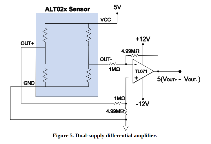
The opamp is setup as a differential amplifier with both sides of the wheatstone bridge sensor going to the +- inputs of the amplifier. (Ignore the resistor values. They are just place holders)
![]()
A better design would use an instrumentation amplifier to avoid loading the wheatstone bridge which could reduce accuracy if not take into account. One way to mitigate this is by using much larger input resistors than the bridge resistance (10k in this case). Here is an example from the datasheet. This app note from TI goes into more details about the tradeoffs for each approach.
This is great, because instrumentation amps cost more and drain more power. The addition of the amp solved my initial problems, but I ran into new ones.
New Problems...
Up until now I've been reusing some parts like the mag sensor since they were out of stock at the time. This meant I didn't have to deal with device to device variances which would impact my amplifier design. Silly mistake.
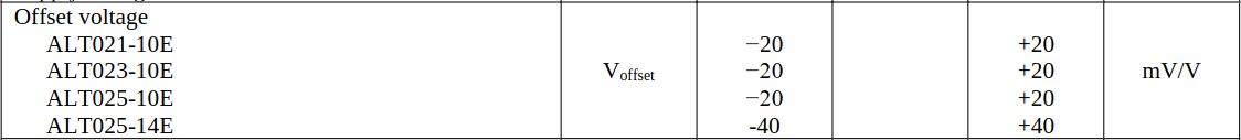
The ALT021 wheatstone bridge DC offset variance is +- 20mV. We can see that in the datasheet and following plots.
Green & Yellow = Sensor 1
Pink & Blue = Sensor 2
![]()
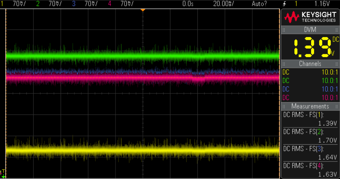
Blue plot is behind the green. See the measurements window on the bottom right for the DC offset Sensor 1 has a difference of 27mV between differential pairs and sensor two has a difference of 9mv. Here are the same devices rotated by 90 degrees.
![]()
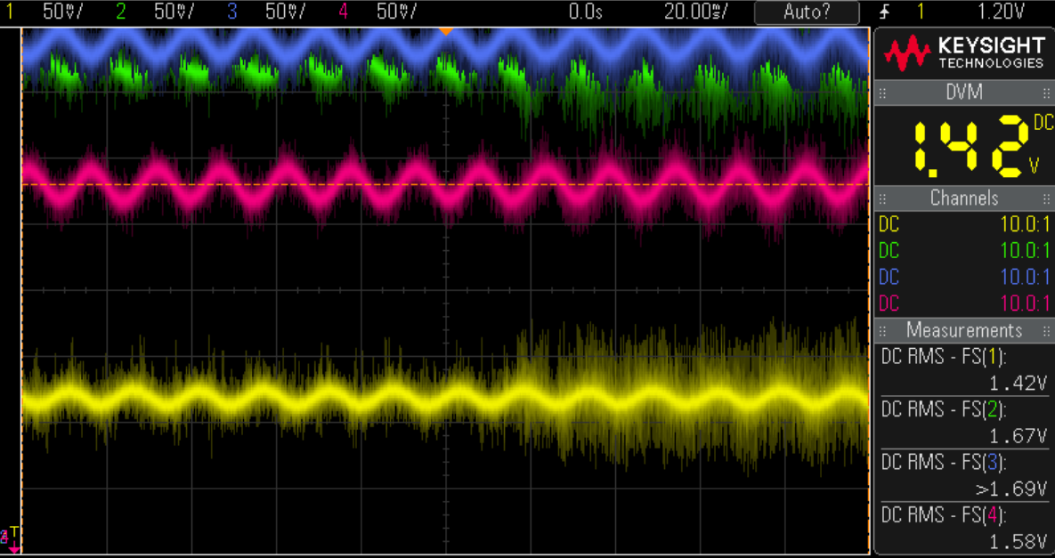
There is a 2mv - 4mv change due to the earth's magnetic field.
![]()
This last plot is with a magnet spinning near the sensors.
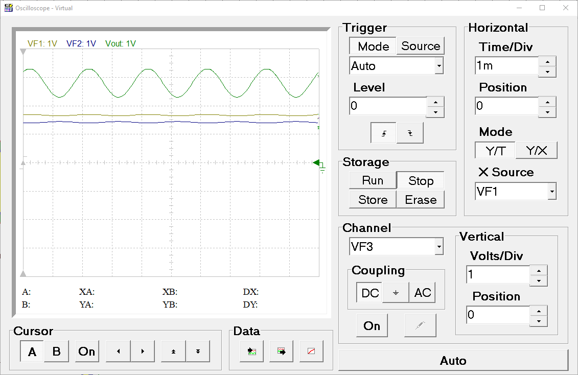
In a perfect world both signals would be centred around Vcc/2 or 3.3V/2 = 1.65V with no magnetic field. The problem starts when you try to amplify the difference between the two differential pairs. The difference in DC offset between sensor 1 and sensor 2 will also get amplified resulting in an output signal with an even larger offset. Here is a simulation with sensor 1.
The bottom two lines are 50mV sine waves with 180 degree offset at 1.41V and 1.68V (sensor 1). We can see the output signal (green) is offset by about 2.6V. Let's take a look at sensor two which had a smaller offset between pairs.
The output signal is now centred at 1.5v.
In summary, there are two factors that impact the DC offset of the amplified signal. The DC offset variance of the wheatstone bridge and the earths magnetic field. This is important to characterize because the analog comparator needs a reference voltage to compare when counting 'zero' crossings. Should it be set to 2.6V for sensor one or 1.5V for sensor two? What happens if the device moves and that offset changes?Possible Solutions
These are some of the possible solutions I considered:
- Apply a high pass filter to remove the DC offset. The issue with this approach is it will filter very slow moving signals i.e. small leaks which could take hours to spin the magnet. Passive components would need to be large to not filter this signal.
- Use software to remove the offset. This would be difficult to do reducing battery life significantly since this is moving the processing to a CPU instead of digital logic as it is now.
- Calibrate each sensor in the factory and correct any offset with shunt resistors. While possible, this is too expensive and time consuming.
- Use a DAC to bias the opamp and correct the offset dynamically. This could work since the calibration only needs to be done once by a uC.
I'm currently prototyping a dynamic calibration method similar to 4 which will be the subject of a future post. Here is the picture proof.
![]()
Enclosure Design Changes
The only major change for this version was to flip the mount orientation of the device. This allows the sensor to sit closer to the magnet, which improved signal detection. However, this meant the LED lens had to be moved. There wasn't enough room to add a cut out with the YDrip logo like the previous design so I opted for a simple circular LED lens.
![]()
Top half of the enclosure with circular LED hole -
Low power small leak detection
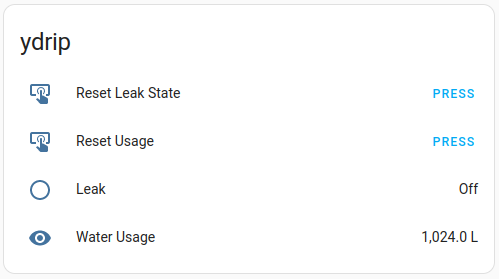
07/19/2023 at 15:25 • 0 commentsI have made modifications to the programmable logic to identify minor leaks and trigger the ESP32-S3 to alert the user, which will have a significant positive impact on battery life. Software-based detection can identify large leaks when the ESP32-S3 wakes up to report regular usage. For instance, if the usage remains consistently high for an extended duration, however this is not implemented yet. All variables can be customized through the YAML file.
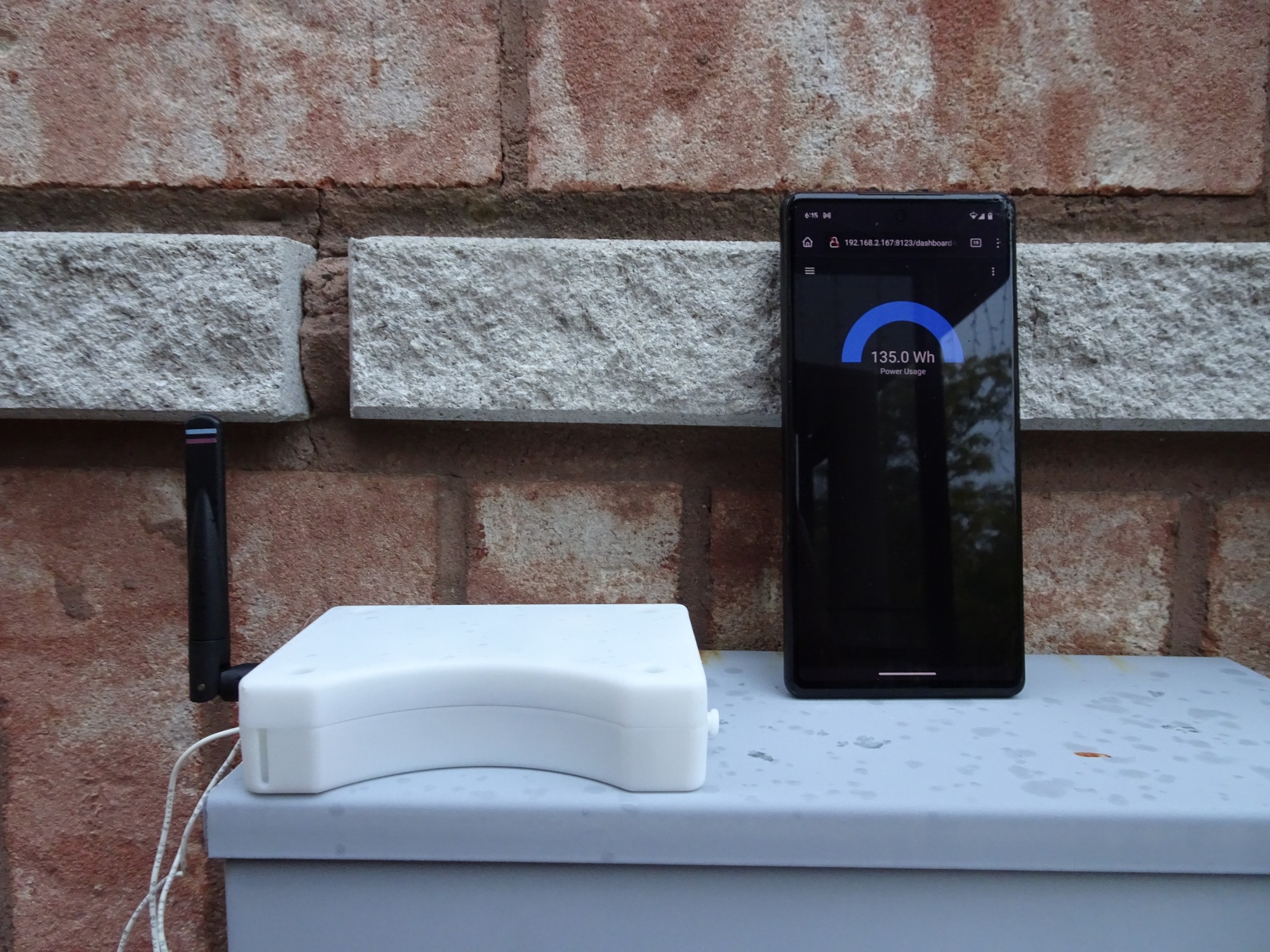
Here is what the Home Assistant Card looks like
Source: https://github.com/YDrip/ydrip-esphome/commit/77c73d2ae2ac85a2539d3d88513e001614a7b9a4 -
Green Hacks Contest Submission
07/03/2023 at 23:05 • 0 commentsI wanted to share that this project will be submitted into Hackaday's Green Hacks contest. This opportunity came at the perfect time because the costs for the development of version 3 of YDrip will be significant. This version will be weatherproof and potentially capable of reading diaphragm-style gas meters (some testing is still required). To achieve this, I am planning on injection molding the enclosure, which has a significant upfront cost.
The theme of the contest is to:
Build a hardware solution that recycles electronics, makes energy harvesting or storage more efficient, or contributes to the sustainability movement.
YDrip contributes to the sustainability movement by giving home owners and business the tools to reduce water consumption. It does this in two ways. The first is by detecting leaks before they turn into costly problems. The second is by giving users real-time water usage data to empower individuals to make informed decisions to conserve water. By visualizing consumption patterns and setting goals, individuals can modify their behavior and adopt water-saving practices. This can include water decisions about whether it is time replace that appliance or how long to water the lawn.
A Unique Solution
The YDrip project addresses a gap in the open source market by offering a versatile solution. Its low-cost and low-power design, combined with programmable digital logic, enables it to be repurposed for various applications. For instance, the hardware's fundamental elements can be utilized to monitor gas meters, and by adding an IR LED, it becomes capable of measuring smart electricity meters. This flexibility and adaptability make YDrip a valuable option for a range of monitoring needs.

 The high/low output of the comparator splits into two paths. The top path measures the total water usage. It consists of two programmable 8 bit counters. When they overflow that triggers a third counter configured as a one shot counter to send a short wake-up pulse to the ESP32S3.
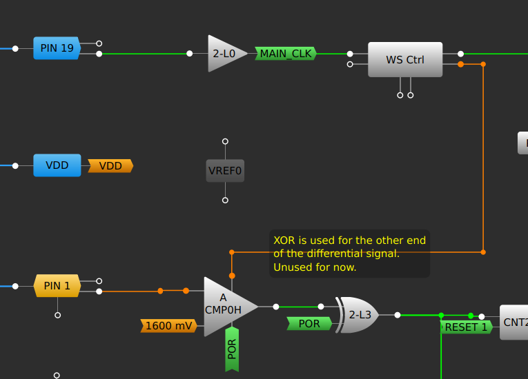
 Green & Yellow = Sensor 1
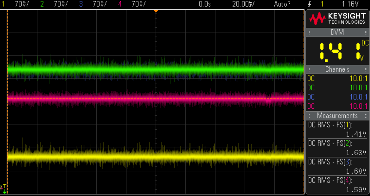
 The bottom two lines are 50mV sine waves with 180 degree offset at 1.41V and 1.68V (sensor 1). We can see the output signal (green) is offset by about 2.6V. Let's take a look at sensor two which had a smaller offset between pairs.
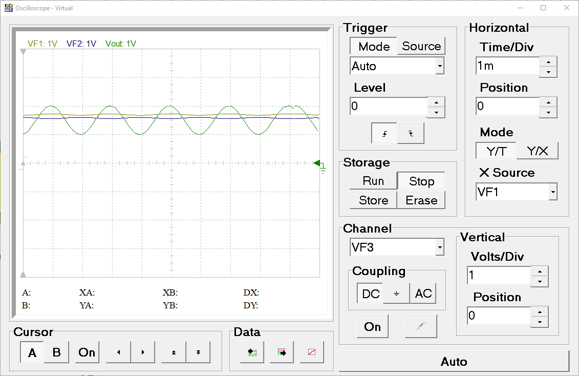 The output signal is now centred at 1.5v.