 Joshua Feist
GEmOPS!
Firmware:
Display driver:
We created an abstracted, nested class structure with two simulated "galvos" controlled through PWM and dir signals as the x and y axes of a display. To satisfy the tight timing requirements of a persistence-of-vision-image, we made use of the FreeRTOS features on the ESP32, with a task in the Display class dedicated to updating the laser's location to draw the image. We could then just update the array of points that the display is trying to draw in order to change the image.
For the PWM, we used ESP32_FastPWM, which gave us good control over the PWM frequency and resolution, as well as letting us ensure that each important component used a different PWM channel.
Website:
Our website has a very simple interface where a user can upload an SVG file of the image they want GEmOPS to draw. The website uses some modified code from the PathToPoints project to convert the SVG file to an array of point locations. These points are both displayed on the website for the user, then passed through websocket communication to the ESP32 to begin drawing with the laser.
Websocket communications:
We needed to transfer more data through websockets than Chrome does in one frame by default, and AsyncWebsocket for ESP32 doesn't by default support multi-frame websocket messages. To get around this, we implemented rudimentary support for multi-frame websocket messages using a variable-length vector of characters to store the data while waiting for more frames.
Hardware:
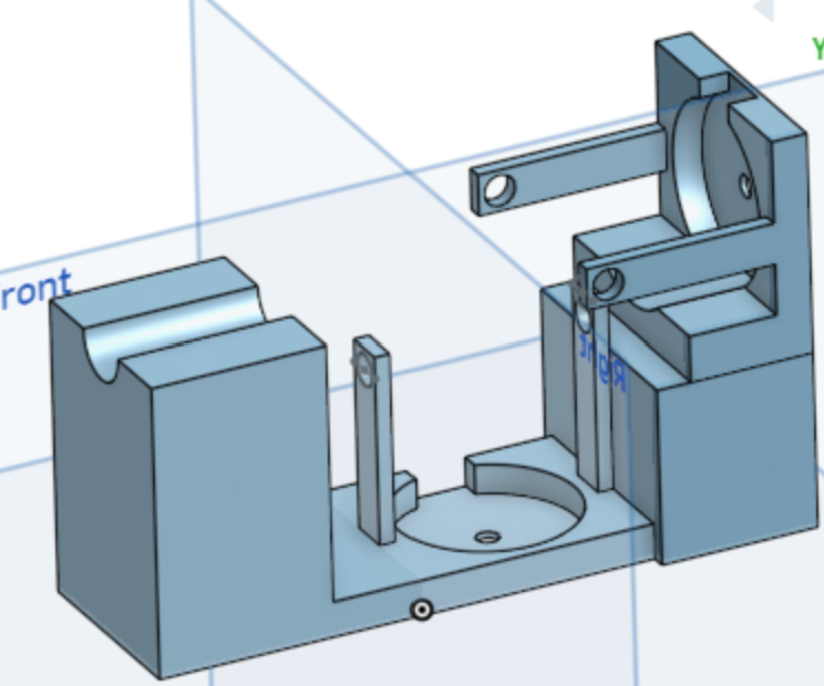
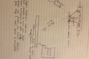
We went through several design phases to create the mounting structure that houses all of the mechanical components, pictured below. The OnShape file can be viewed here. We 3D printed this structure using standard PLA with tree supports and a thin layer thickness.
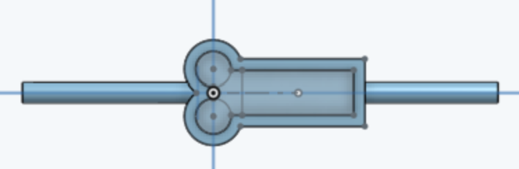
We assembled the two mirror shafts next. One is pictured below and can be 3D printed from this OnShape link. We glued two of the 3mm magnets into the circular divots, making sure that the magnets are oriented in opposite polarities to each other. Then we cut out a piece of the sticker mirror and stuck it into the rectangular space.
We then stuck a bearing on each end of the axel, and these can be slotted into the arms that extend over the electromagnets in the mount.
With the opposite polarity of the two magnets on the mirror shaft, PWMing the electromagnet can, at this point, rotate the mirror. To get the mirror to be able to point to a specific pixel location, we needed to add an opposing force to the movement of the mirror. To accomplish this, we wound two springs out of thin copper wire and glued them the back of the mirror shaft and the mount arm, as in the picture below.
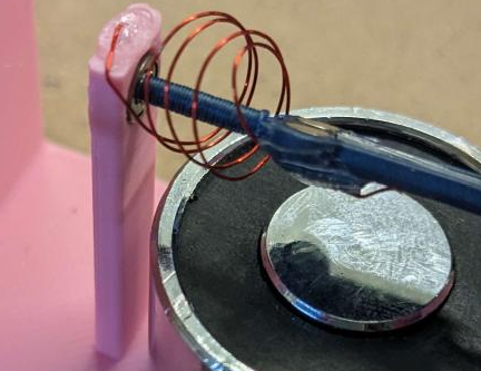
In gluing the springs, we also set the home orientation of the mirrors. We turned on the laser to help calibrate this position, making it so the laser bounces off the top mirror, hitting the center of the bottom mirror, then bouncing to the wall.
 ThunderSqueak
 Evan Stanford
 Sproket
 Ted Yapo
A cool project. I have tried a lot different methods, but i like yours.
I tried speakers with mirrors, misused stepper motors or bldc motors, the Coils and magnts from CD/DVD player heads.
I have all the parts for http://elm-chan.org/works/vlp/report_e.html but not built yet.