The purpose of this project was to monitor a well water level 100' away from the house in the back yard with no available power supply. The project was orignally done with a Raspberry Pi Pico W but decided to go with a ESP32-Wroom-32U for the external antenna.
This project has three options:
Option 1: Fixed Positon Solar Panel
Option 2: Scanning Solar Panel (scans all positions every 30 mins)
Option 3: Tracking Solar Panel (Based on GPS Coordinates)
_XpR21b8a2o.jpeg?auto=compress%2Cformat&w=740&h=555&fit=max)
_Zp5Fkx1cgF.jpeg?auto=compress%2Cformat&w=1280&h=960&fit=max) The ESP32 collect the sensor data and sends the data to InfluxDB and then imported to Grafana for trending and visulization over Wifi. InfluxDB Cloud & Grafana in this project are free and allow for 30days of historical data. You would need to setup accounts and obtain your InfluxDB token and create your dashboard. I will not go over this process in this built as a simple google search can give you some examples how to setup the accounts and just replace "<Your Token here>", "<Your bucket here>" & "<Your Organization>" in the provided code to publish the data to InluxDB.
The ESP32 collect the sensor data and sends the data to InfluxDB and then imported to Grafana for trending and visulization over Wifi. InfluxDB Cloud & Grafana in this project are free and allow for 30days of historical data. You would need to setup accounts and obtain your InfluxDB token and create your dashboard. I will not go over this process in this built as a simple google search can give you some examples how to setup the accounts and just replace "<Your Token here>", "<Your bucket here>" & "<Your Organization>" in the provided code to publish the data to InluxDB.


Wiring Diagram explanation:
Power(+) from both the battery and the solar panel is run through a 4 pin switch to elminate all sources of power while working. I found that both the Solar input and battery input needed to be switched or the ESP32 would not shutdown due to the voltage from the solar panel. Ensure your switch does not connect these two sources as they have different voltage potenitals.
Each power source is run through its own INA226 to measure the voltage, current and power then connected to the Solar Power Management Board by DFRobot. More information on the board can be found here: https://www.dfrobot.com/product-1712.html
3.3V and ground is supplied to the INA226s from the ESP32 and SDA/SCL for communiation.
The ESP32 is connected to the Solar Power Management Board with a USB cable to provide the power supply to the ESP32.
The ESP32 supplies the 5V+/- to the level sensor and pin 33 is used for the analogue signal from the level sensor. Important to note that the level sensor selected has a higher range then the well can get too so the output voltage from the sensor does not exceed the limit for the ADC on the ESP32. A 10M Range level sensor was used for a well that is 7M deep and the output voltage of the sensor at max range is 4.5V so at 7M the voltage would be around 3.3V
(7 - 0) / (10 - 0) = (V - 0.5) / (4.5 - 0.5). V ≈ 3.3V
If this is not possible in your situation a voltage divider could be used to drop the voltage instead
ESP32 Pins 21/22 are used for the communciation from the INA226s and the light intensity module.

Code Breakdown (Fixed Solar Panel):
MicroPython script designed for an ESP32 microcontroller. Here's a breakdown of its functionality:
Importing Libraries: The code starts by importing various libraries required for different functionalities, such as networking, timekeeping, hardware control, and sensor readings.
GPIO Configuration: The code configures the GPIO pins defined in the <b>gpio_pins</b> list as inputs with pull-down resistors. It also disables the Bluetooth functionality by setting the pin 0 as an output and setting its value to 0.
I2C Initialization: The code initializes the I2C interface using the <b>SoftI2C</b> class with specified SCL (clock) and SDA (data) pins.
INA226 Device Initialization: The code initializes two INA226 devices connected via I2C (0x40 and 0x44 addresses). It sets the variables <b>ina1</b> and <b>ina2</b> accordingly and flags <b>I2C1_connected</b> and <b>I2C2_connected</b> to indicate successful connections.
LED Initialization: The code initializes an LED pin (pin 2) as an output.
Blinking LED: The code defines a timer event (<b>timer1</b>) that toggles the state of the LED using the <b>blink</b> function. It then blinks the LED once by setting its value to 1.
ADC Initialization: The code initializes...
Read more »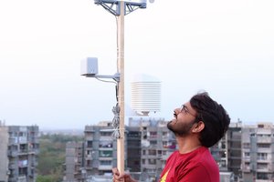
 Open Green Energy
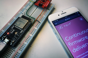
 nils.westerlund
 Don R-Crenshaw
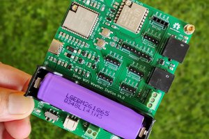
I have a very similar well. Can you share some information on the level transmitter?