Michael Wessel
PicoRAM 2090
A Raspberry Pi Pico (RP2040)-based 2114 SRAM Emulator and Multi-Expansion for the Busch
2090 Microtronic Computer System.
Final Demo Video on YouTube:
I have written about the Microtronic here before, and done a few Microtronic-related projects:
- https://hackaday.io/project/11560-the-talking-microtronic-computer-system-emulator
- https://hackaday.io/project/176466-microtronic-the-next-generation
- https://hackaday.io/project/180252-a-retro-authentic-microtronic-emulator
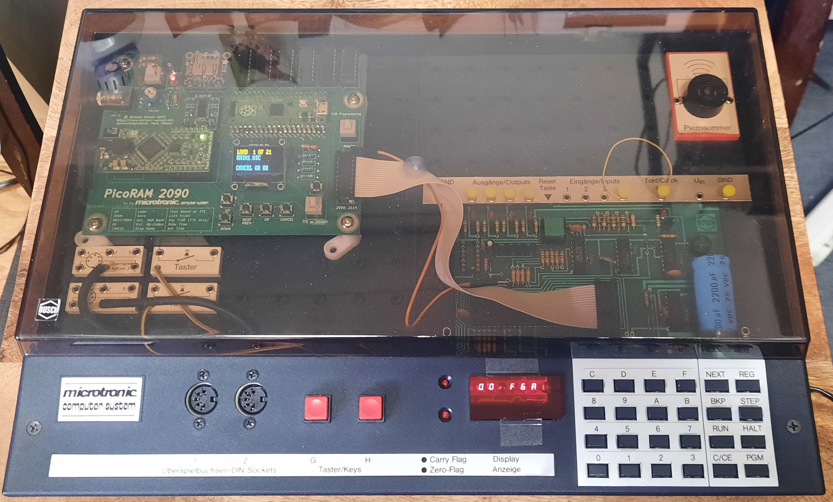
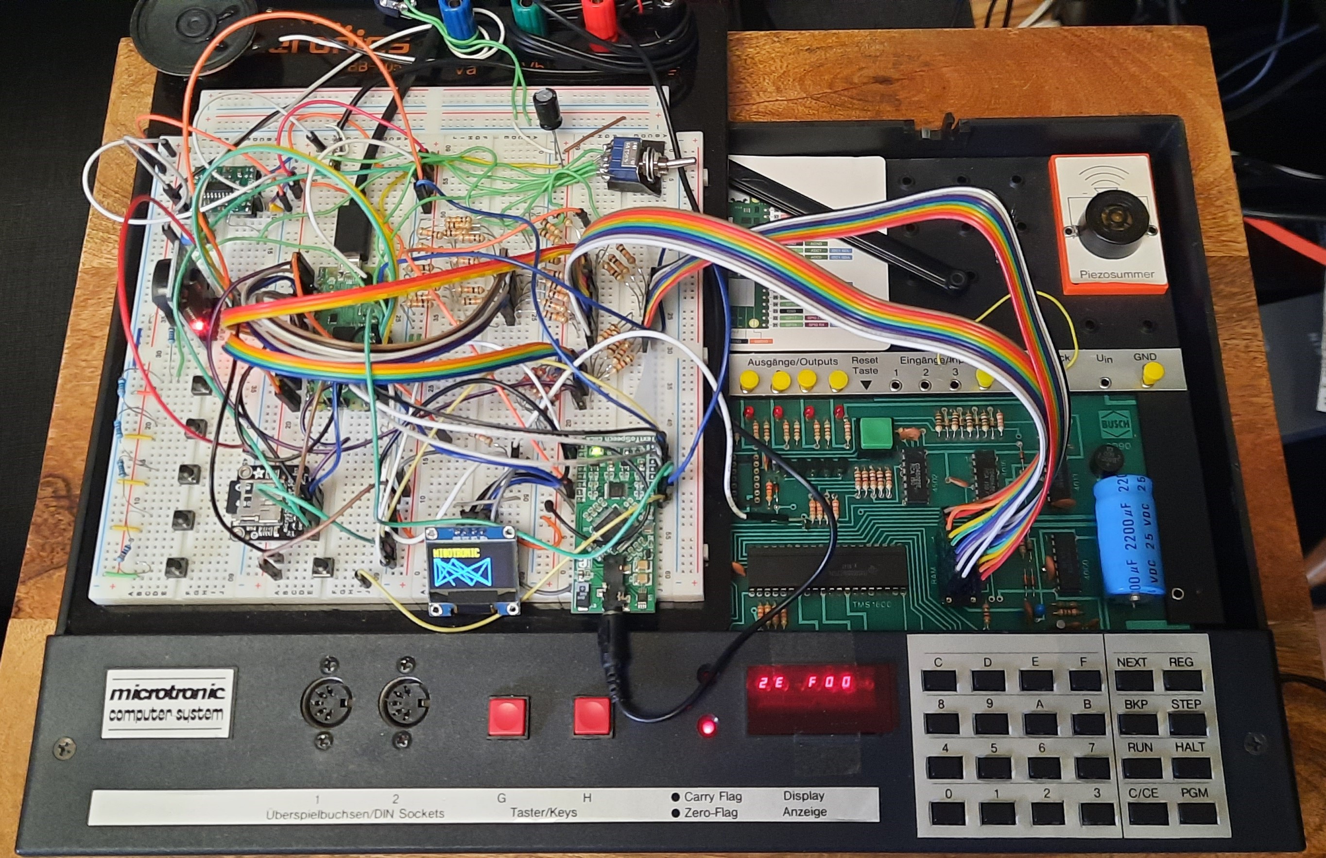
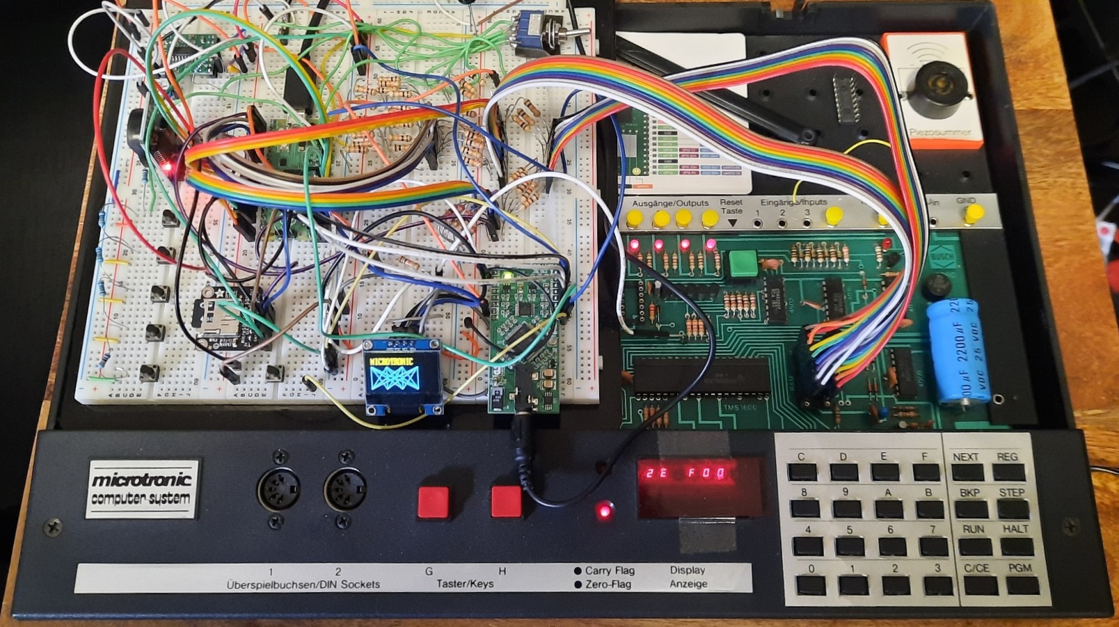
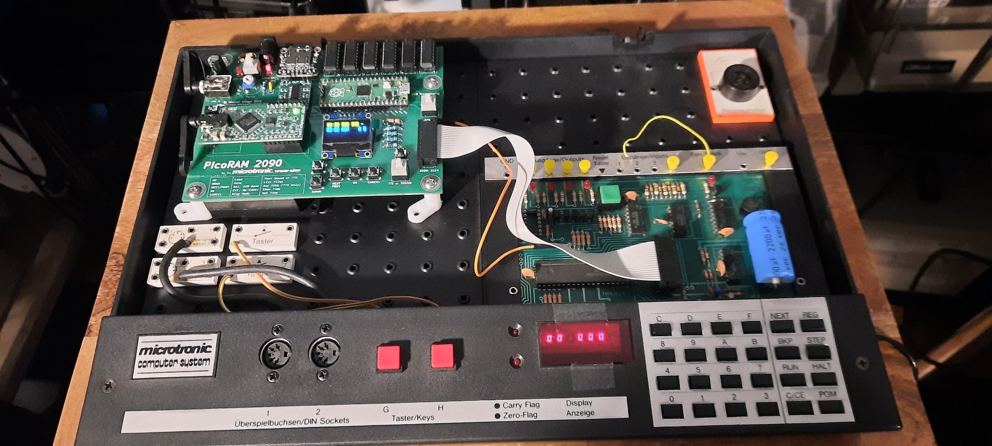
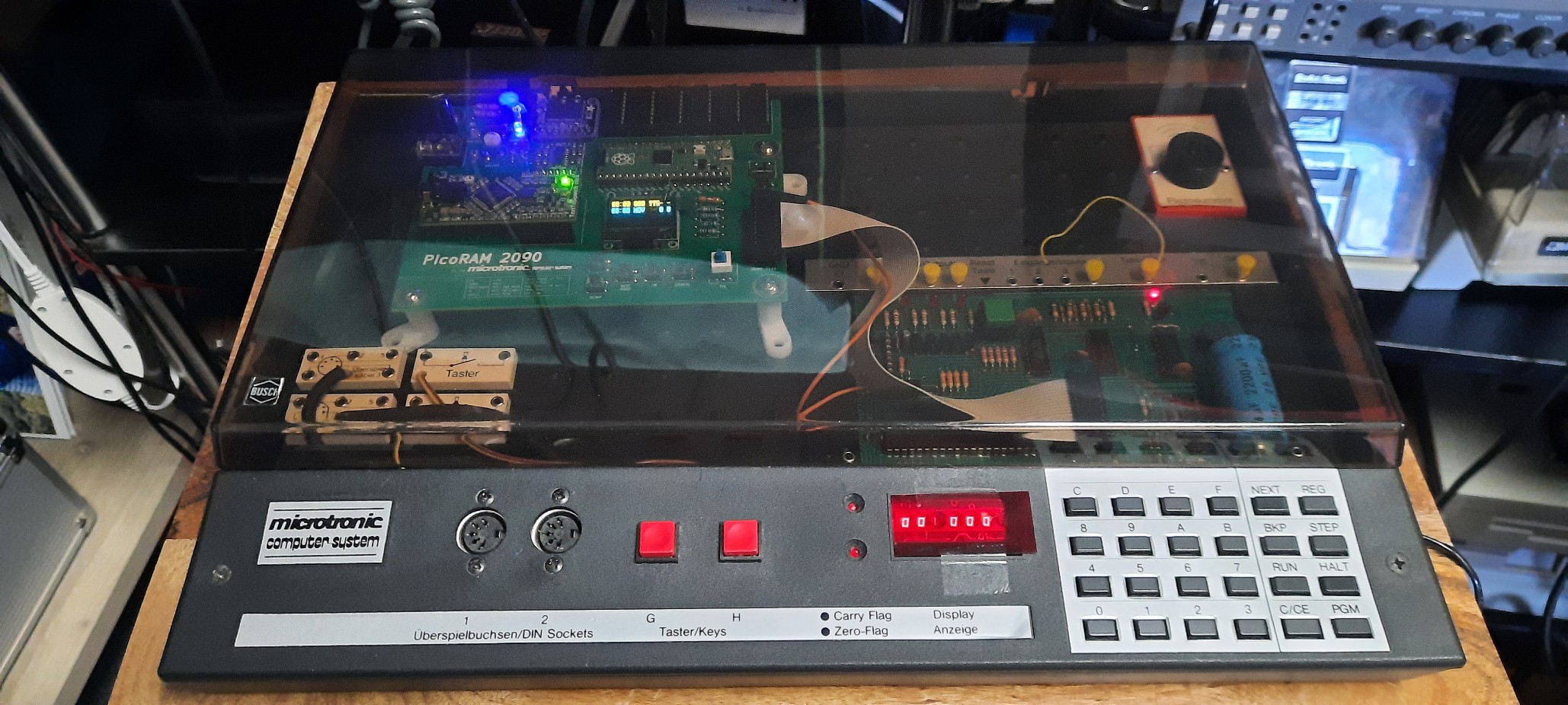
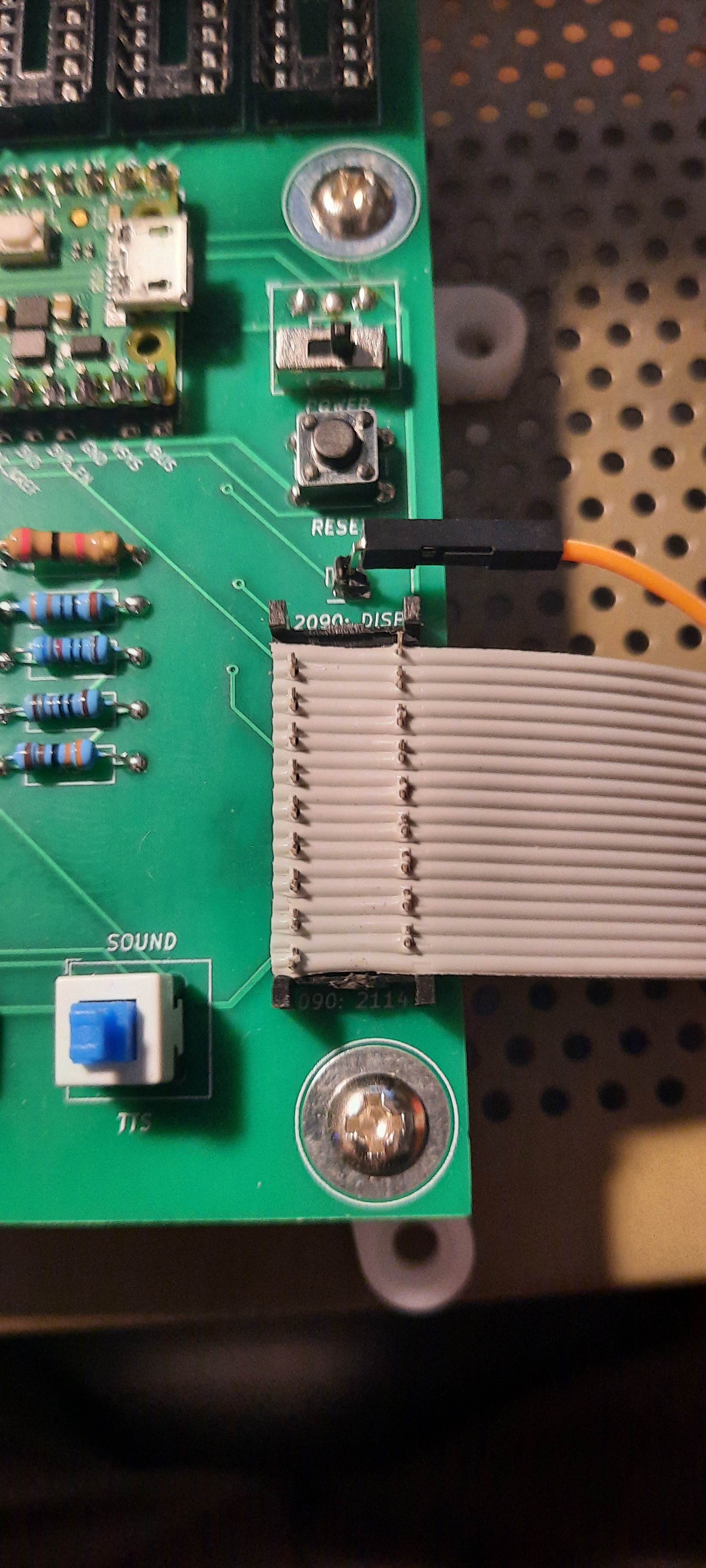
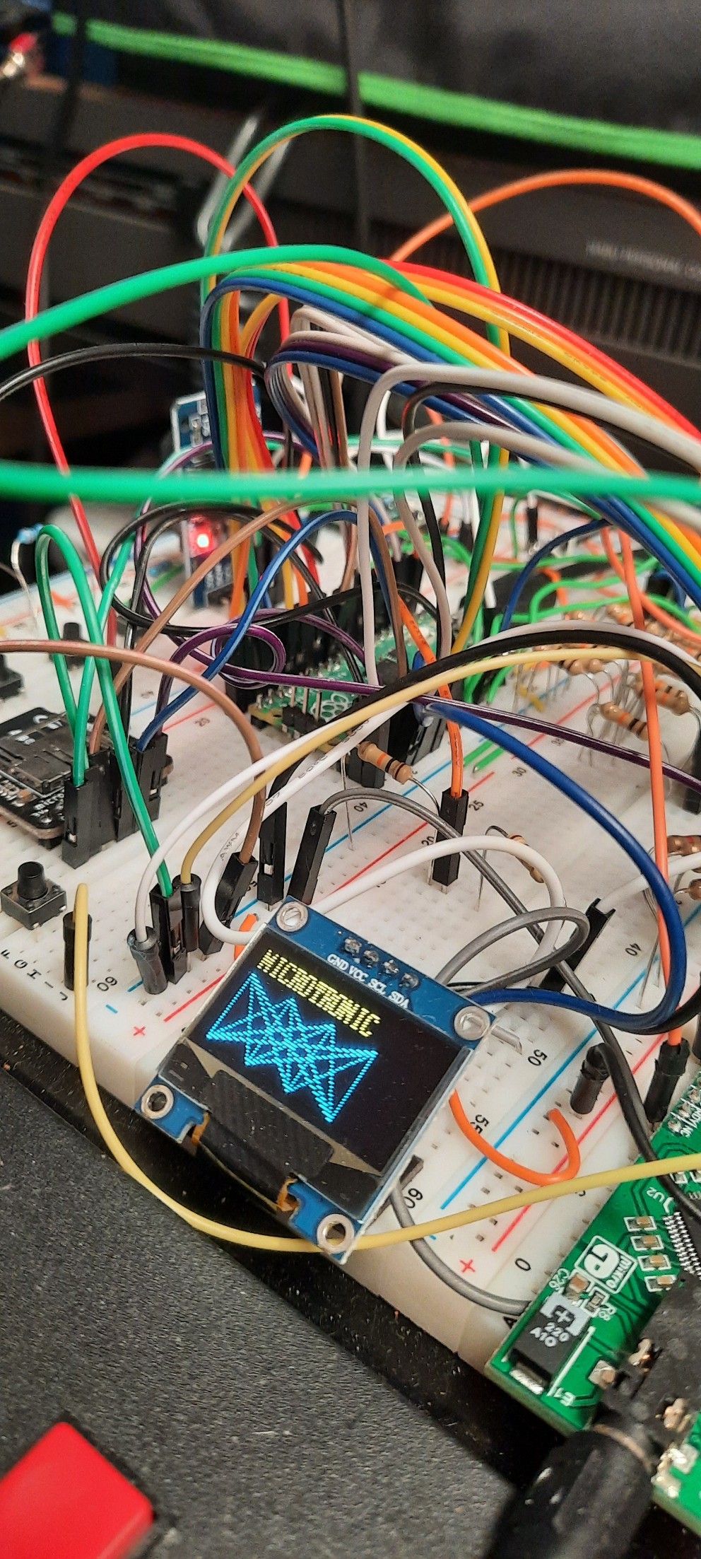
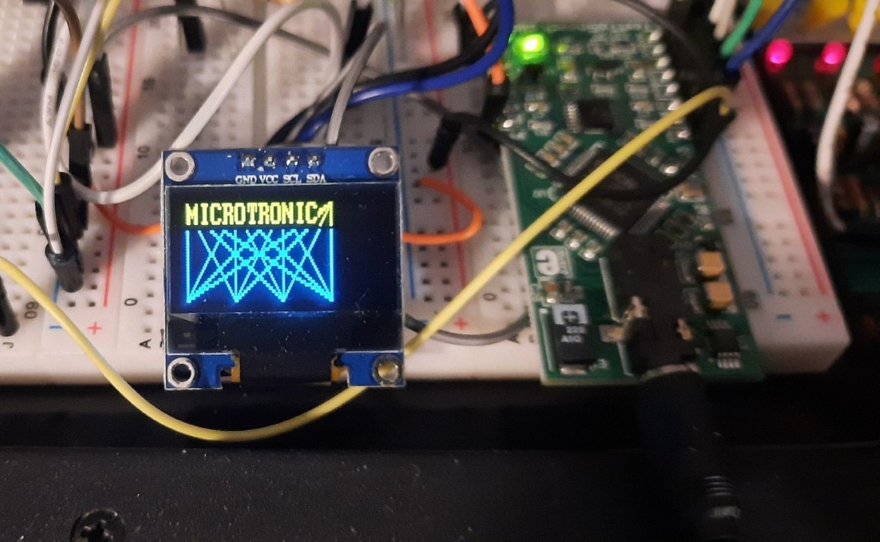
The final PicoRAM 2090 in the Microtronic:


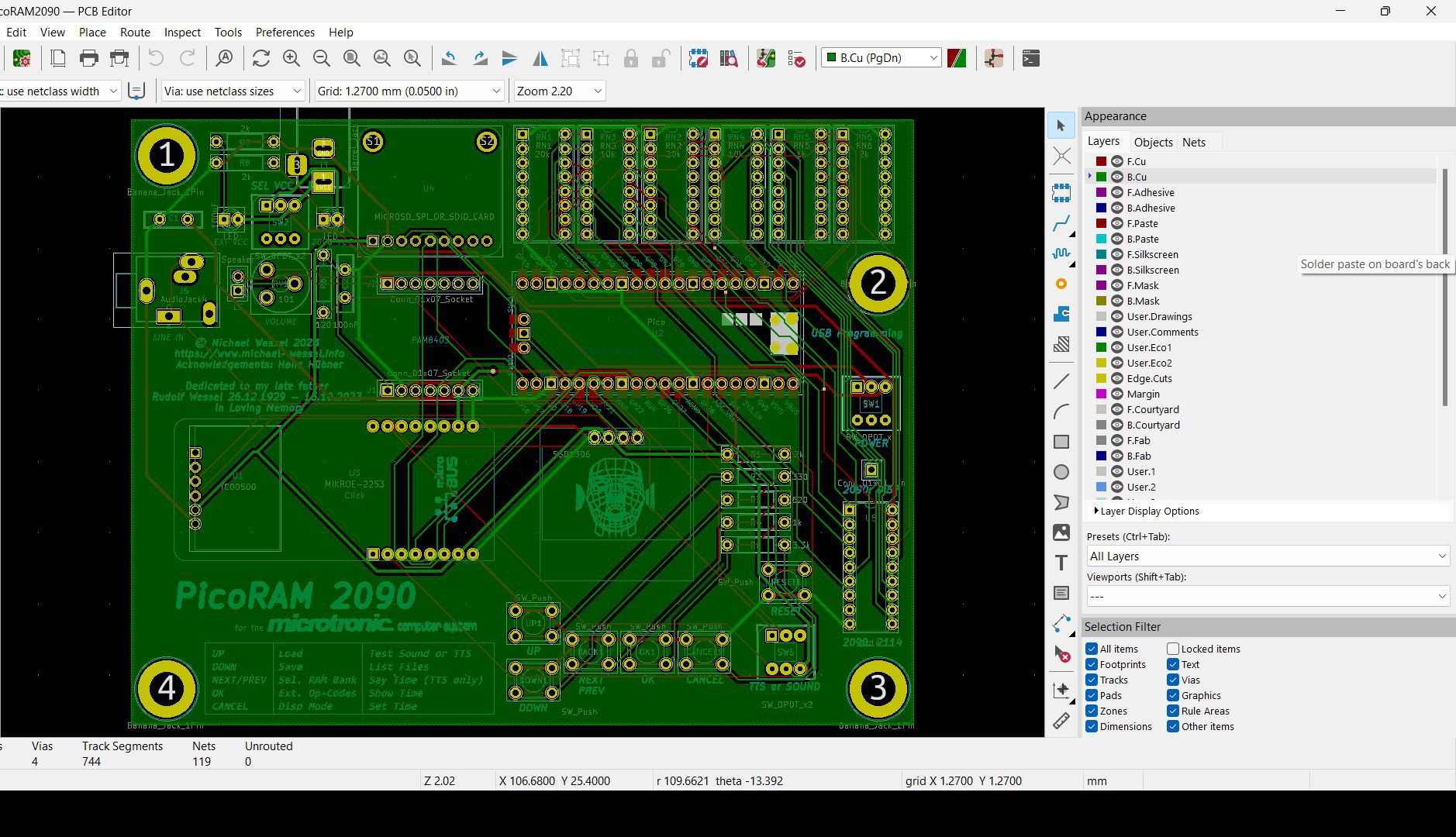
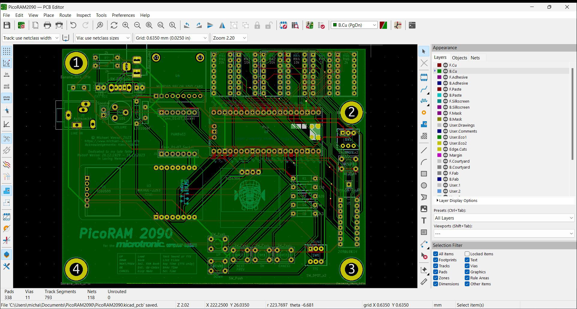
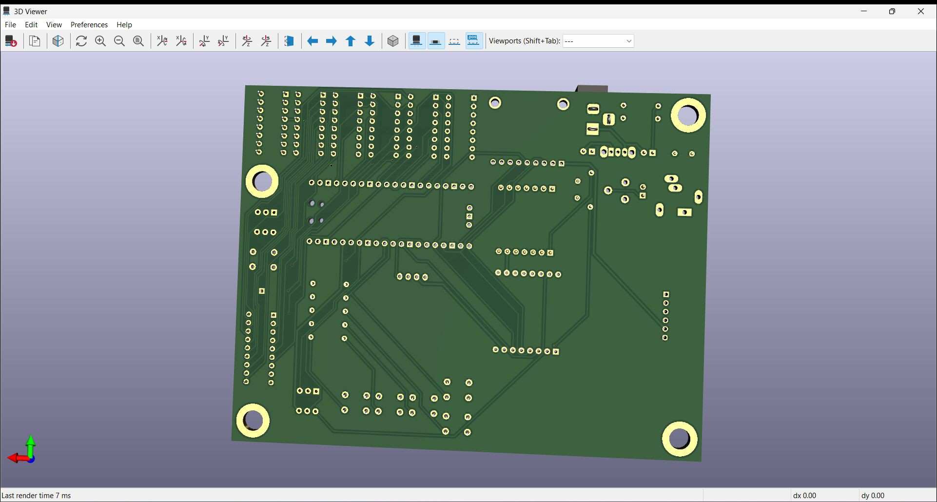
The firmware is attached to the project, as are the Gerber files. Please also have a look at the Github repo.
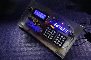
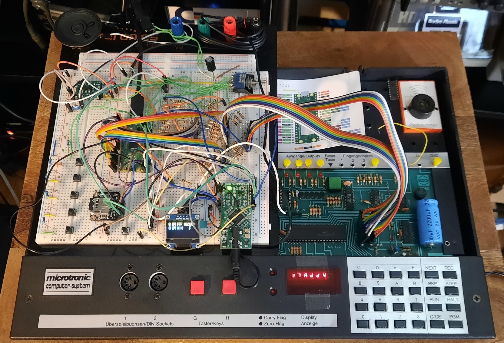
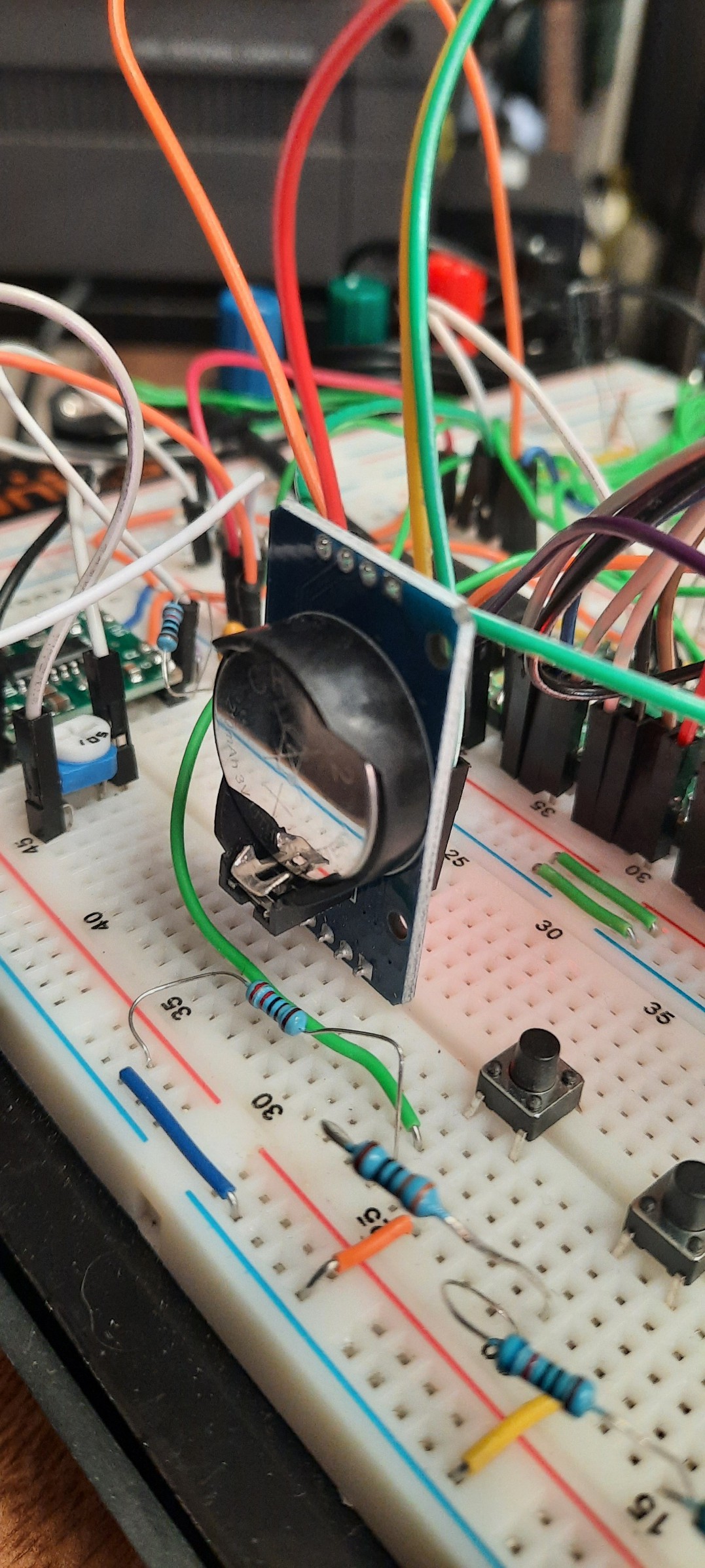
Early Prototype Pictures: 
Latest News / Updates
It's done! PicoRAM 2090 is finished. The GitHub repo has been updated and now contains an extensive README, the Gerbers, and the firmware. I'll upload the source code a little bit later. But for now, Makers / builders have everything they need to replicate it!
Here's the final demo video on YouTube:
Log Entries for RetroChallenge 2023/10 Participation
It's done - the RetroChallenge 2023/10 October month is coming to an end! This is my final video for the challenge which wraps it up - a full demo of most of the implemented features (with the exception of the RTC - see Log Entry 4 for that instead). I implemented everything I promised here: https://www.retrochallenge.org/2023/10/rc202310-halftime-update.html
All RetroChallenge 2023/10 Log Entries
Some more details in the final RetroChallenge log entry: https://hackaday.io/project/192655-picoram-2090/log/224691-retrochallenge-202310-log-entry-6-final-wrap-up-demo-video
DS3231 Real Time Clock: https://hackaday.io/project/192655-picoram-2090/log/224507-retrochallenge-202310-log-entry-5-ds3231-for-microtronic
Text, Speech, & Graphics Demo: https://hackaday.io/project/192655-picoram-2090/log/224486-retrochallenge-202310-log-entry-4-demo
Extended Op-Codes, Bank Switching: https://hackaday.io/project/192655-picoram-2090/log/224467-retrochallenge-202310-log-entry-3
SD Card Memory Dumps: https://hackaday.io/project/192655-picoram-2090/log/224327-retrochallenge-202310-log-entry-2
Overall Idea and Setup: https://hackaday.io/project/192655-picoram-2090/log/224259-retrochallenge-202310-log-entry-1
By now, the SD card interface, banked memory, graphics, text, speech, and sound extensions are working! Here is a little demo:
About
This project started out as an attempt to emulate the 2114
SRAM found in the Busch
2090 Microtronic Computer
System - a fully
compatible "drop in" replacement using the Raperry Pi Pico. A Pico-based SRAM emulator facilitates SD card-based storage of Microtronic memory dumps / its program memory, and hence of programs. Saving to and loading back of programs to SD card is much faster and more convenient than the Microtronic cassette interface (also, the files can be edited and created on the PC / Mac).
Later, this project became more ambitious - utilizing the first core of the Pico for SRAM emulation, the second core is now being used to implement a co-processor / IO extension for the Microtronic. By now it features a banked memory expansion (16 memory banks!), OLED text and graphics output, speech, and sound output. See the latest video above for a short demo.
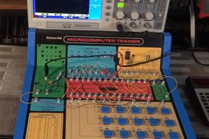
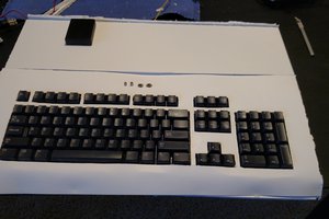
Original Background & Context / Historical Account of the Project
This is the Microtronic Computer System from 1981, a 4bit educational computer - on the left you see the cassette interface. It also has an Arduino-based speech synthesizer connected to its output ports (an older project of mine, ~ 2016):

The 2114 was a popular and widely used 1024x4 Bit SRAM chip. It was used in many early arcade games from the late 1970s and early 1980s. Pinout:

The Microtronic is a relatively slow educational 4bit microcomputer, so timing is not critical. A standard Pico is more than fast enough for the Microtronic. Note that the Microtronic doesn't...
Read more »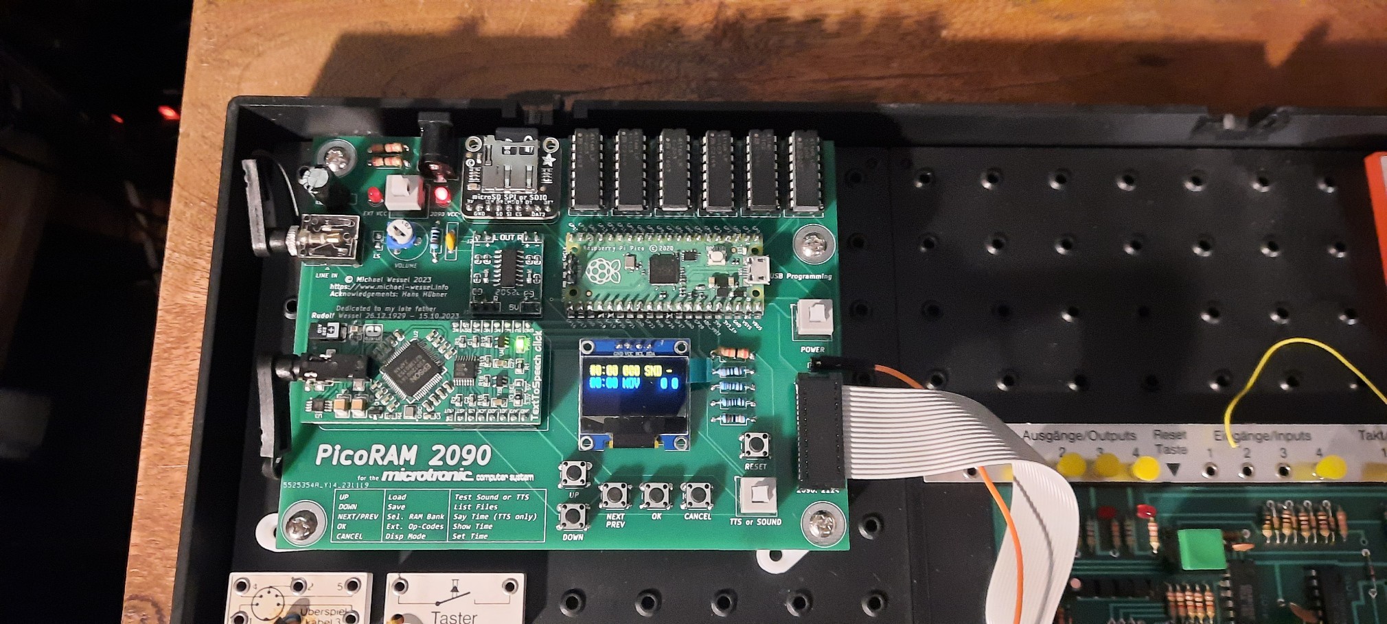


 Alex Bowen