Close
0%
0%

Exploring the Science Fair Microcomputer Trainer

An exploration of Radio Shack's educational computer from 1985

Similar projects worth following
This fascinating machine was released in 1985 by Radio Shack - for $ 29.95. Like my favorite, the Busch Microtronic 2090 Computer System, it uses a mask-programmed TMS microcontroller from the TMS 1000 family - in this case, the TMS 1100 clocked at 400 kHz. The Microtronic uses a TMS 1600 @ 500 kHz. Naturally, I was curious how these machines differ. This is a series of videos where I explore the Science Fair.

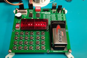
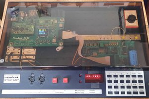
In the first video, we are taking a first look and measure the performance of the system in terms of executed instructions per second - how does it compare to the Microtronic, Kosmos CP1, and the Philips Masterlab? How many MIPS (Million Instructions per Second) can it do? Or is it more in the HIPS (Hundred Instructions per Second) region? See for yourself: 


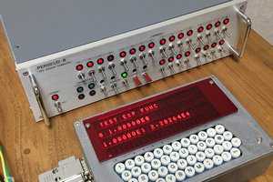
In the second video, I give an in-depth overview of the system and we are writing a complex program to explore its emulated, virtual machine language. The program aims to give an impression of the machine's capabilities and covers a good amount of the instruction set, including hex display & LED output, keypad input, arithmetics, comparisons, conditional branching, and different addressing modes, including indexed memory access. The different registers and build-in "firmware sub-routines (CALs)" are explained as well. After watching this video, you'll have a pretty good overview and understanding of the machine's capabilities:


Here is my instruction set cheat sheet here - the Science Fair manual is quite instructive and contains great examples, explaining every op-code in good detail. However, it really lacks a number of overview tables. This table is meant to fill that gap: 

0 | KA            | 0          | A <- keyboard (use with JUMP, Flag = 0 when key, else 1)
1 | AO            | 1          | Hex disp <- A
2 | CH            | 2          | A <-> B exchange, and Y <-> Z as well
3 | CY            | 3          | A <-> Y exchange
4 | AM            | 4          | M(Y) <- A 
5 | MA            | 5          | A <- M(Y)
6 | M+            | 6          | A <- A + M(Y)
7 | M-            | 7          | A <- A - M(Y) 
8 | TIA n         | 8 n        | A <- n
9 | AIA n         | 9 n        | A <- A + n 
A | TIY n         | A n        | Y <- n
B | AIY n         | B n        | Y <- Y + n
C | CIA n         | C n        | A = n -> Flag ( then 0, else 1)
D | CIY n         | D n        | Y = n -> Flag ( then 0, else 1) 
E | CAL #routine  | E n        | Call subroutine, argument in A if needed
F | JUMP high low | F high low | Goto 16*high + low 
----------------------------------------------------------------------------
RSTO: 0 - turn off HEX display 
SETR: 1 - turn on LEDs (from Y: 0..6) 
RSTR: 2 - turn off LEDs
----: 3 - not used 
CMPL: 4 - complement A (bit flip) 
CHNG: 5 - exchange A <-> A', B <-> B', Y <-> Y', Z <-> Z' 
SIFT: 6 - shift right A
ENDS: 7 - make end sound  
ERRS: 8 - make error sound
SHTS: 9 - make short sound 
LONS: A - make long sound
SUND: B - make organ sound (from A) 
TIMR: C - timer (from A) 
DSPR: D - show mem at addresses 50 - 51 (LEDs) and 52 (HEX)
DEM-: E - Dec. sub of 2 digits -> DEC; M(Y) <- M(Y) - A in DEC; Y <- Y - 1
DEM+: F - Dec. add of 2 digits -> DEC; M(Y) <- M(Y) + A in DEC; Y <- Y - 1

Please find the program from the video in the files section.

In the third video - "In 80 Nibbles around the Towers of Hanoi!" (SCNR) - I am demonstrating Jason's implementation of the recursive version that he describes in his log entry

DumpTool.ino

Revised Arduino code to dump the ROM from a TMS1000 series chip. Tested on the Gakken FX R-165 and the Science Fair Microcomputer Trainer.

ino - 15.05 kB - 04/09/2024 at 17:05

Download

sfmt-comqref-appxb.pdf

Science Fair Microcomputer Trainer Command Quick Reference Table (card) and "Appendix B" explaining the use of the officially "NOT USED" E3 CAL INPT instruction.

Adobe Portable Document Format - 691.28 kB - 04/07/2024 at 19:13

Preview
Download

science-fair-demo.txt

Simple Science Fair demo program from the 2nd video.

plain - 1.43 kB - 02/23/2024 at 16:35

Download

  • Inferring Obfuscated ROM Code on the TMS1100

    Jason Jacques04/09/2024 at 16:32 0 comments

    As mentioned in decle's excellent entry on Dumping the TMS1100, some TMS1000 series chips obfuscated the ROM code by always asserting the high-bit in each instruction byte. In those chips the test mode only allows extraction of a partial ROM.

    Interestingly, the patent to which decle referred also highlights that you can selectively execute the code on the TMS1000 series chips. Due to the specific details of the TMS1000 series instruction set, all bytes which really do have the high-bit set are branch or call instructions.

    This means that if we execute the unknown instruction and we end up somewhere unexpected (i.e. the program counter is out of order) then the instruction really was a branch or call, and the high-bit really was set. If we end up at the very next instruction, it was (probably) not a jump.

    I've updated decle's Arduino code to support this inference and automatically execute instructions to identify jumps as it dumps the ROM. I've also included a few more heuristics that help deobfuscate some of the more tricky corner cases; of which there are quite a few. The curious can check out the code for more details.

    You can download your own copy here.

    To accurately indicate any potentially incorrect instructions, the code puts a question mark (?) after any suspect bytes in the output. For the vast majority of instructions this will not apply and the heuristics mean that many of the suspect bytes will be correct, even if marked. For example, the code correctly dumps the complete known ROM of the Microcomputer Trainer despite being uncertain about 39 (of the 2048) instructions. If you don't want the question marks in the output they can be turned off.

    #define WARN 0

    However, if you are going to try and use the ROM in an emulator, or inspect a disassembled version line-by-line, having the question marks gives an indication of where to look if something goes awry.

    You can use the revised code to dump the ROM from both the Science Fair Microcomputer Trainer, and the Gakken FX R-165 (if you're willing to take a soldering iron to your vintage computer). The code may work for other TMS1000 series chips, but is untested. I've also updated it to (hopefully) dump the ROM from the TMS1600 in the Busch Microtronic 2090. Michael recently discovered his Microtronic ROM is not obfuscated, but it did require a few small tweaks which my edits (should) handle.

    To get started, I recommend watching decle's informative clocking video. This will help you ensure you can control the TMS chip. Taking control of the clock is an important first step. Here, decle uses a sped up Blink sketch.

    For most chips you'll also need to build the inverting amplifiers, as shown in decle's log entry.

    As noted in the entry, I was able to get my Science Fair to dump the ROM at just 6V, but not all chips will work at such a low voltage. Using 6V does mean that, as long as you use the voltage divider on pin O7 to protect your Arduino, you can avoid the extra circuitry. This does require that you uninvert the high/low signals, but I provide a define statement that you can use to (un)swap the logic levels.

    #define INVERT 0

    If you're having trouble, or want a more detailed overview, then I've made a video showing how to check that all the signal levels are appropriate for the TMS chip. Note that I am using inverted logic here (I have set the above code to 1), as I am using the inverting amplifiers.

    Finally, if you're looking to dump the TMS1600 you need to hold R8 high, instead of R6/R10, and you'll need to set the chapter size to four, as it has twice the ROM of the TMS1100.

    #define CHAPTERS 4 

    As Michael discovered, the TMS1600 also has slightly different timing requirements; but this should already be handled by the LOAD_WAIT and LOAD_HIGH constants. This aspect of the code is untested though, so your milage may vary and you may need to make your own modifications.

    Good luck, and happy ROM dumping!

  • The Missing Manual [Pages]

    Jason Jacques04/07/2024 at 19:30 0 comments

    The Science Fair Microcomputer Trainer is a great learning tool, but I’ve always felt the manual made it difficult to quickly (re)acquaint yourself with the instruction set. This seems particularly important with the the type of sporadic put-down/pick-up use that you might expect with any learning platform, especially one aimed at youngsters.

    Unlike the Gakken FX R-165, on which it is based, the Science Fair version lacks a quick reference card (available at the end of the Japanese manual scan). Sure, the Microcomputer Trainer has the opcodes listed on the front panel, but it's not quite the same. So, please, allow me to present: The Missing Manual [Pages].

    You can download your own copy here.

    Some time ago I put together my own Command Quick Reference for the Science Fair. It’s not a direct translation of the Japanese, as I added a few extra hints to it (e.g. listing the run mode and games) and corrected a couple of minor errors from the original documentation; but it is clearly heavily inspired by it.

    As you can see, I keep a printed copy with the unit for reference. If you print it at 85% and trim it with ~5mm margin (to the content) it neatly matches the dimension of the manual. I also find it useful as a cross reference back to the official instruction definitions in the Science Fair Microcomputer Trainer manual (as with the Japanese version, the page numbers refer to the callout boxes).

    Some time later I discovered further details about the R-165's E3 CAL INPT instruction. Unfortunately the relevant pages were missing from the Japanese manual scan, but a fellow going by the name mikecat_mixc put up an interesting article on the R-165 which (with the use of Google Translate) allowed me to expand my documentation.

    I subsequently added the included “Appendix B” to cover the use of the E3 CAL INPT instruction with the Science Fair, which, even though it is marked as NOT USED, is present and works just fine. Without access to the the Japanese manual this section of the document was much more speculative. You'll have to forgive my potentially poor explanations and examples!

    In addition, although it was great to be able to use the "hidden" input feature, the transistor inverter approach seemed suboptimal. Using the "official" circuit means that you can’t use the keyboard and CAL INPT at the same time. However, I realised the limited number of patterns displayed on the seven segment display allowed us to abuse the “HEX. LED” as the input for a simple diode OR gate from which to supply the activation logic and power for the K inputs.

    The diode approach actually ensures the display is on during CAL INPT. More importantly, it allows you to use both the keyboard and the CAL INPT command “simultaneously”. I present both options in the document. We have since discovered that the requirement of the display being “on” is just an artefact of the logic used to read the control keys, and the way the output PLA is used (in part) to scan the K inputs.

    More recently I obtained the “missing” pages from the Japanese scan (and English translations), and my Appendix B and example program is very different from the originals. There are some possible minor misrepresentations, as this document predates our latest investigations, but I’m happy enough with it. Importantly, I think a diode logic approach, offering access to all four K inputs, is an improvement due to the enhanced functionality it offers.

  • Dumping the TMS1100

    decle03/05/2024 at 13:21 0 comments

    This post details the approach that Sean Riddle and I took when dumping the code contained in the Science Fair Microcomputer Trainer (SFMT) back in 2015.  This built on previous work by Kevin Horton (aka Kevtris).  Although I'm writing this up, credit should go to Sean and Kevin.  If this description inspires you to try ripping apart your favourite 1970s toys and microwave ovens to dump the firmware, I'd encourage you to check out Sean's website to see if he's done the hard work for you already. 

    The SFMT is based around the TMS1100.  This is a derivative of the TMS1000 microcontroller released by Texas Instruments in 1974.  The TMS1100 has a 4-bit CPU, 2K of ROM and 128 nibbles of RAM housed in a 28pin DIP.  In the SFMT the firmware in the 2K ROM contains an emulator of a 4-bit virtual machine, and seven "games".  It's quite impressive.

    Dumping the firmware out of the ROM within a TMS1xxx is theoretically pretty simple.  Fundamentally, there are two approaches.

    • Take your TMS1xxxx and grind the top off the package, exposing the die.  Photograph the die.  Remove the top metal layer from the die using acid, and photograph it again.  Reverse engineer the ROM contents from the die images.  This approach has the downside that it's pretty hard core and destructive, but it's comprehensive and is guaranteed to work.
    • Observe that US patent 4024386, which describes the TMS1000, details a test mode that can be used to extract the ROM contents from the pin O7.  Reverse engineer this process which starts at column 27, line 20, and read the ROM contents electrically.  Whilst this is non-destructive, it has a number of drawbacks.  Firstly, the summary of the test mode in the patent is incomplete and somewhat confusing.  Secondly, in addition to the ROM, the TMS1xxxx allows customisation of two other aspects of the processor, the instruction PLA and the output PLA.  The test mode does not allow these customisations to be inspected.  Finally, over time Texas Instruments made changes to the TMS1xxx design to cripple the test mode.  Whilst it is possible to dump early chips, by the time the TMS1100 used on the SFMT was in production the method detailed in the patent would only dump 7 bits of each instruction, and it is believed that the even later chips disabled this technique altogether.

    In the case of the SFMT, Sean had already followed the first method, but in the process of decapping the chip the die had been damaged.  It was early in Sean's decapping career and this happens sometimes, but as a consequence he didn't have a complete picture of the ROM.  I didn't fancy destroying my SFMT, so we investigated reconstructing the work done by Kevtris to make use of the second method.

    After some fiddling, we came up with the following circuit that could be connected to an Arduino or similar that would allow us to exercise the TMS1100 test mode:

    In this case I used an Arduino Micro to control the TMS1100, using six transistors as inverting level shifters up to the 9V PMOS logic used by Texas Instruments.  These are used to drive the clock, INIT (reset) and four K input pins.  ROM data is then read out of the O7 pin.  A couple of resistors are needed on O7, one to pulldown the open collector output, and another to protect the Arduino from the 9V logic of the TMS1100.  The only other wiring necessary is power and a connection from the R10 output (confusingly labelled R6 on the SFMT) to +9V.  @Jason Jacques has subsequently found that it's possible to undervolt the TMS1100 and run it at 6V, bypassing the need for level shifting and allowing it to be connected directly to an Arduino.  Obviously, both the TMS1100 and Arduino are technically out of spec at this point, so your mileage (and damage) may vary.

    We then use this Arduino program to dump the ROM.  This clocks addresses into the K...

    Read more »

  • Welcome to the project, decl!

    Michael Wessel02/23/2024 at 17:00 0 comments

    @decle has joined us - great to have you on board, welcome!  Check out his YouTube channel.

    He implemented Nybl - a Science Fair emulator using the original ROM that runs on the Intellivision, and also has developed a method of dumping a TMS 1xxx ROM using the test mode. Great stuff!

  • In 80 Nibbles Around the Towers of Hanoi

    Michael Wessel02/23/2024 at 16:41 0 comments

    I made a demo video showing Jason's recursive implementation of the Towers of Hanoi - enjoy!

  • Solving Towers of Hanoi recursively in 80 nibbles

    Jason Jacques02/22/2024 at 01:49 0 comments

    As Michael mentioned, he somewhat nerd sniped me with the the idea of squeezing a Towers of Hanoi solver in not the Science Fair Microcomputer Trainer. As an avid fan of both the Gakken FX R-165 and the Science Fair Microcomputer Trainer, I could't let it go uncompleted.

    With a good number of iterations, I managed to squeeze an "interactive" solver down to fit into just the 80 nibbles (40 bytes!) of the Microcomputer Trainer's memory.

    The full listing follows.

    The Listing

    Memory address in column 1, 2, and 3; value to enter in column 4. Logical labels, relevant to program execution, are in column 5. The final two columns are a disassembly of the instruction, back to labels and opcodes. These correspond one-to-one with the final assembly language source (provided at the end of this entry).

    ; towers of hanoi for science fair microcomputer trainer
    ; (c) 2024 LambdaMikel & jtjacques
    
    ; assembled with https://arpruss.github.io/r165.html
    
    ; stack
    ; set 0x50 to a
    ; set 0x51 to c
    ; set 0x52 to b
    ; set 0x53 to 0
    
    ; initial state
    ; set z (0x6b) to n (0, 1, 2, 3)
    ; set y (0x6e) to 3 (pointer to m 0x53)
    
    ; start at hanoi (0x17), mode 2
    ; when pause (0x33, 0b0110011)
    ;     reset, inspect y (0x6e)
    ;     moves: inspect memory at 0x5[y] (from), 0x5[y+1] (to)
    ;     resume at resume (0x00, or simply reset), mode 2
    ; when hlt (0x29, 0b0101001), program complete
    
    0         0000000   00        B         resume              AIY
    1         0000001   01        2                             2
    2         0000010   02        5                             MA
    3         0000011   03        B                             AIY
    4         0000100   04        2                             2
    5         0000101   05        4                             AM
    6         0000110   06        B                             AIY
    7         0000111   07        D                             D
    8         0001000   08        5                             MA
    9         0001001   09        B                             AIY
    10        0001010   0A        4                             4
    11        0001011   0B        4                             AM
    12        0001100   0C        B                             AIY
    13        0001101   0D        B                             B
    14        0001110   0E        5                             MA
    15        0001111   0F        B                             AIY
    16        0010000   10        6                             6
    17        0010001   11        4                             AM
    18        0010010   12        8                             TIA
    19        0010011   13        3                             3
    20        0010100   14        B                   lbl_6:    AIY
    21        0010101   15        1                             1
    22        0010110   16        4                             AM
    23        0010111   17        2         hanoi               CH
    24        0011000   18        D                             CIY
    25        0011001   19        0                             0
    26        0011010   1A        F                             JUMP
    27        0011011   1B        3                             lbl
    28        0011100   1C        6                             _0
    29        0011101   1D        F                             JUMP
    30        0011110   1E        2                             lbl
    31        0011111   1F        5                             _1
    32        0100000   20        B                   lbl_3:    AIY
    33        0100001   21        C                             C
    34        0100010   22        2                             CH
    35        0100011   23        B                             AIY
    36        0100100   24        1                             1
    37        0100101   25        2                   lbl_1:    CH
    38        0100110   26        5                             MA
    39        0100111   27        E                             CAL
    40        0101000   28        6                             SIFT
    41        0101001   29        F         halt      lbl_2:    JUMP
    42        0101010   2A        2                             lbl
    43        0101011   2B        9                             _2
    44        0101100   2C        C                             CIA
    45        0101101   2D        0                             0
    46        0101110   2E        F                             JUMP
    47        0101111   2F        2                             lbl
    48        0110000   30        0                             _3
    49        0110001   31        B                             AIY
    50        0110010   32        9                             9
    51        0110011   33        F         pause     lbl_4:    JUMP
    52        0110100   34        3                             lbl
    53        0110101   35        3                             _4
    54        0110110   36        B                   lbl_0:    AIY
    55        0110111   37        F                             F
    56        0111000   38        2                             CH
    57        0111001   39        B                             AIY
    58        0111010   3A        D                             D
    59        0111011   3B        5                             MA
    60        0111100   3C        B                             AIY
    61        0111101   3D        4                             4
    62        0111110   3E        4                             AM
    63        0111111   3F        B                             AIY
    64        1000000   40        E                             E
    65        1000001   41        5                             MA
    66        1000010   42        B                             AIY
    67        1000011   43        3                             3
    68        1000100   44        4                             AM
    69        1000101   45        B                             AIY
    70        1000110   46        C                             C
    71        1000111   47        5                             MA
    72        1001000   48        B                             AIY
    73        1001001   49        5                             5
    74        1001010   4A        4                             AM
    75        1001011   4B        8                             TIA
    76        1001100   4C        1                             1
    77        1001101   4D        F                             JUMP
    78        1001110   4E        1                             lbl
    79        1001111   4F        4                             _6
    80        1010000   50        A         source
    81        1010001   51        C         dest
    82        1010010   52        B         spare
    83        1010011   53        0         return
    

    Setup

    The program does require you to specify the initial parameters for the first stack frame in the data area at addresses 0x50-0x53. This tells the computer the layout of your pegs, and sets the exit condition. For convenience I have included them at the end of the listing and you can simply carry on entry past the program area into the data area. However, for completeness they are as follows: 

        0x50: source (peg A),
        0x51: destination (peg C)
        0x52: spare (peg B)
        0x53: 0 (return label)

    While the names are arbitrary (you could call them pegs 1, 2, and 3, for example, if you prefer) the final return label (0) is required to allow the program to exit correctly.

    You also need to configure two more parameters: the number of discs between 0 and 3 in 0x6B (the Z register) and the least significant nibble marking the end of the stack in 0x6E (the Y register), 3.

    Important Note: documentation for the FX R-165 and Microcomputer...
    Read more »

  • ChatGPT 3.5 programs the Science Fair (in assembler)

    Michael Wessel02/21/2024 at 03:42 2 comments

    Not entirely unexpected, and not entirely serious either, but nonetheless - impressive! While it mostly failed to translate its generated assembly code into machine language (It's not a good assembler), the delivered assembly code actually worked in the end.

    Yes, it required significant hand-holding on my behalf - however, unlike for common assembly language dialects such as Z80, 6502, 68k, x86, etc., it certainly hasn't been trained on large amounts of Science Fair trainer code.

    Now, the real question is of course - when can we expect Science Fair Assembler support in Copilot, Microsoft? :D

    Here you go: 


    Can you help me write an assembly program?

    ChatGPT

    Of course! I'd be happy to help you write an assembly program. Could you please provide more details about what you want the program to do? Additionally, let me know which assembly language you're working with (e.g., x86, ARM, MIPS) so I can tailor the code accordingly.

    It's the Science Fair microcomputer trainer. Heard of that?

    ChatGPT

    Yes, I'm familiar with the Science Fair microcomputer trainer. It's a simple microcomputer trainer kit often used for learning assembly language programming. What specific task or program would you like to create for it?

    Can you create a counter that uses the hex display.

    ChatGPT

    Sure! Here's a simple assembly program for the Science Fair microcomputer trainer that implements a counter and displays its value on the hex display. This assumes an 8-bit microcontroller and a 7-segment hex display.

    ORG 0x00      ; Start address
    
    Main:   MOV R0, #0     ; Initialize counter
            MOV R1, #0     ; Initialize display index
            
    Loop:   MOV P1, R0     ; Output counter value to hex display
            CALL Delay      ; Delay for some time
            
            INC R0          ; Increment counter
            
            CMP R1, #15     ; Check if display index reached 15 (hex F)
            JZ  ResetIndex  ; If so, reset display index
            INC R1          ; Increment display index
            JMP Loop        ; Repeat loop
            
    ResetIndex:
            MOV R1, #0     ; Reset display index
            JMP Loop        ; Repeat loop
    
    Delay:  ; Delay subroutine
            MOV R2, #255   ; Initialize delay counter
            
    DelayLoop:
            DJNZ R2, DelayLoop  ; Decrement delay counter and loop until zero
            RET

    This program initializes a counter (R0) and a display index (R1) to zero. It then enters a loop where it outputs the value of the counter to the hex display, increments the counter, and checks if the display index has reached 15 (hex F). If it has, it resets the display index. After each iteration, it calls a delay subroutine to introduce a delay before updating the display again.

    Please note that the actual addresses and instructions might vary depending on the specific microcomputer trainer and assembly language you're using. Make sure to adapt the code accordingly.

    That's the wrong instruction set.

    ChatGPT

    Apologies for the confusion. Let's try again using an assembly language suitable for the Science Fair microcomputer trainer. Below is an example program using a hypothetical assembly language compatible with the Science Fair microcomputer trainer:

    ORG 0x00      ; Start address
    
    Main:   MOV R0, #0     ; Initialize counter
            MOV R1, #0     ; Initialize display index
            
    Loop:   MOV P1, R0     ; Output counter value to hex display
            CALL Delay      ; Delay for some time
            
            INC R0          ; Increment counter
            
            CMP R1, #15     ; Check if display index reached 15 (hex F)
            JZ  ResetIndex  ; If so, reset display index
            INC R1          ; Increment display index
            JMP Loop        ; Repeat loop
            
    ResetIndex:
            MOV R1, #0     ; Reset display index
            JMP Loop        ; Repeat loop
    
    Delay:  ; Delay subroutine
            MOV R2, #255   ; Initialize delay counter
            
    DelayLoop:
            DJNZ R2, DelayLoop  ; Decrement delay counter and loop until zero
            RET
    

    This assembly program initializes a counter in the X register and continuously increments it. It updates the hex display with the current value of the counter. If the counter reaches 15 (hex F), it resets the counter to 0 and updates the hex display accordingly. It includes a delay subroutine to introduce a delay between each update of the display.

    Please...

    Read more »

  • Welcome, Jason Jacques!

    Michael Wessel02/20/2024 at 16:02 0 comments

    Jason joined the team! He reached out to me after my first YouTube video so that I could set the record straight and correct some inaccuracies, in particular, the release year of the Science Fair trainer. Jason pointed me to the original Radio Shack catalog from 1985 when it was first released. I could then correct the trainer's debut year from 1976 to 1985.  

    I then also took the opportunity to  "nerd-snipe" him in a second email, regarding my attempted (but failed) recursive Towers of Hanoi implementation on the Science Fair - with his extensive Science Fair knowledge and programming experience, would he be able to fit it in? 

    And indeed, he was! I hence invited him to join the team - he gave me permission to include his recursive version of the Towers of Hanoi on the project. But nobody explains a program better than the author - so I am hoping that he will use his new team member privileges to upload his program here and maybe write a sentence or two explaining it. 


    So, if you like, take it from here, @Jason Jacques - either by adding it directly to the details section, or as a new log entry, as you like!

  • Towers of Hanoi won't fit easily

    Michael Wessel02/19/2024 at 15:48 0 comments

    I spent a few hours trying to fit in the recursive version of Towers of Hanoi (e.g., see here: https://www.cs.cmu.edu/~cburch/survey/recurse/hanoiimpl.html):

    FUNCTION MoveTower(disk, source, dest, spare):
    IF disk == 0, THEN:   
      move disk from source to dest
    ELSE:    
      MoveTower(disk - 1, source, spare, dest)   
      move disk from source to dest              
      MoveTower(disk - 1, spare, dest, source)  
    END IF

    Previously, I succeeded doing this for the Microtronic - the Microtronic doesn't offer a native stack, nor programmatic access to the RAM! RAM is only for program memory (-> Harvard Architecture), and writable memory is register memory only. So implementing a stack for recursion is not so straight forward, but it is possible by shifting its set of 16 "extra registers" up and down to emulate push and pop operations to a stack (altogether, the Microtronic has 2x 16 4bit registers):


    Also, there are no computed or "indirect" jumps - it is not possible to put a return address in a register (or memory) location and simply jump "indirectly" to the address stored there.

    Hence, I used numeric jump labels and something I called a "jump block" - to do a computed jump (i.e., a return from a recursive call or subroutine to a variable address), I am comparing a register that I  set up to act as "return" register to these numeric jump labels and execute conditional jumps  accordingly. 

    Putting the 2 techniques together I was then able to implement both a value and a return stack and hence could execute the recursive version of the towers of Hanoi for up to n=4 disks; you can find the Microtronic program here to get the idea:
    https://github.com/lambdamikel/picoram2090/blob/main/software/1.1/HANOI.MIC

    Would the same techniques work for the Science Fair? In particular, since the Science Fair offers indexed memory access - load & store to the data region from 0x50 - 0x5F via the Y "index" register is possible, using the op-codes `AM (4)` and `MA (5)`, I though at least the stack implementation should be much more straight forward: 

    4 | AM | 4 | M(Y) <- A
    5 | MA | 5 | A <- M(Y)
    

    And indeed, using the Y-register as index into the data region, and being able to do "stack arithmetics"  using the `AIY (B)` op-code

    B | AIY n         | B n        | Y <- Y + n

    worked like a charm - much more straight-forward than on the Microtronic!

    Like with the Microtronic, "computed" jumps to computed target addresses stored in memory or a register are impossible, so I require the same "jump block" mechanism for the Science Fair as well.

    Unfortunately, I ran out of program space on the Science Fair - I would have needed exactly 15 more nibbles! My program overlaps with the data region (from 0x50 on) that I would need for the (value and return) stack - but in principle, the ideas are sound, and it should work (if I only had more space...) 

    But here is the program so far: 

    // CONCLUSIONS - DOESN'T HAVE ENOUGH MEMORY :-(
    // JUMP BLOCK OVERLAPS DATA REGION (50... ) 
    
    //
    // Towers of HANOI on the Science Fair Microcomputer Trainer
    // (C) 2024 by LambdaMikel
    //
    // Memory and registers need to be set up manually:
    // 
    // 1. Load n = 1, 2, 3, 4 into B (@ 6C) 
    // 2. Point Y (@ 6E) to 53 
    // 3. Load Label 0 into 53 
    //
    // 4. Set up first stack frame by hand: 
    // 50 = SOURCE : A
    // 51 = DEST   : C
    // 52 = SPARE  : B 
    // 53 = RET    : 0
    //
    //
    // MoveTower(n, source, dest, spare) 
    //
    
    00 2  CH     GET n value from B: A <- B  
    01 C  CIA 1  A <> 1 ? -> FLAG = 1, JUMP REC. CASE  
    02 F  JUMP   REC CASE @ OB - JUMP executed when FLAG = 1 (A <> 1) 
    03 0  
    04 B 
    
    // A = 1 
    // Base case 
    // Y points to RET label 
    
    // move disk from source to dest
    // no mem space for output! only n display 
    
    05 1  A0     HEX DISP 
    
    06 2  CH     Store n value back into B: A -> B   
    
    07 F  JUMP   JUMP BLOCK @ 50 
    08 5
    09 0 
    
    // A > 1
    // Recursive case 
    // Y points to RET label 
    
    // Compute n - 1 by adding F (= Sub 1) 
    
    0A 9  AIA F  (= SUB 1) 
    0B F 
    0C 2  CH     Store A = n-1 into B: A -> B 
    
    // Prepare first recursive...
    Read more »

  • "It's really very impressive when you look at the disassembly."

    Michael Wessel02/19/2024 at 15:37 0 comments

    "Decle" wrote the following interesting comment on my second Science Fair video:

    @decle 7 hours ago The virtual machine and monitor within the SFMT code is implemented in about 1K (the other 1K of memory is used for the 6 built in games). It's really very impressive when you look at the disassembly. Although the TMS1100 has 128 nibbles of RAM, only 80 are available for you program code. There rest is used for the internal state of the virtual machine. 16 nibbles are used for the data memory available to your code. 10 nibbles are reserved for the virtual machine registers and the rest is used to record state like key presses, hex output values etc.

    I think he is probably referring to the ROM bits that have been read out by Sean Riddle: 

    https://www.seanriddle.com/tms1100.html

View all 11 project logs

Enjoy this project?

Share

Discussions

wally wrote 02/26/2024 at 16:50 point

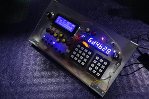
Thanks Michael for sharing your videos! I am looking for more :)

  Are you sure? yes | no

Dan Maloney wrote 02/23/2024 at 22:04 point

Hi Michael -- Fantastic trip down memory lane, although I have to admit that by 1985 I had already "aged out" of Science Fair stuff. Too bad, this would have been fantastic training for me only a few years earlier.

Wrote this up for the blog, thanks so much for tipping us off. Nice stuff!

  Are you sure? yes | no

Michael Wessel wrote 02/23/2024 at 23:18 point

Thanks Dan. It's good to see that you guys are currently on a Science Fair retro trip ;-) Please give most of the KUDOS for the ingenious Towers of Hanoi program to Jason - it's amazing what he has done there. Cheers MIchael

  Are you sure? yes | no

Similar Projects

Does this project spark your interest?

Become a member to follow this project and never miss any updates