 JP Gleyzes
What is it ?
End of August, my brother designed a small PCB to accomodate the excellent project OpenXsensor on Raspberry Zero.
Mstrens published a very versatile solution to use this cheap but powerful MCU to get a multiProtocol solution for telemetry.
Here is how this project can be used to build an inexpensive PCB to add the following sensors to your FS-IA6B receiver. (could be easily adapted to other receivers).
- a variometer
- a battery voltage sensor
- a GPS tracker
- an optionnal current sensor
- 1 to 4 extra channels added to your 6 channels FS-IA6B
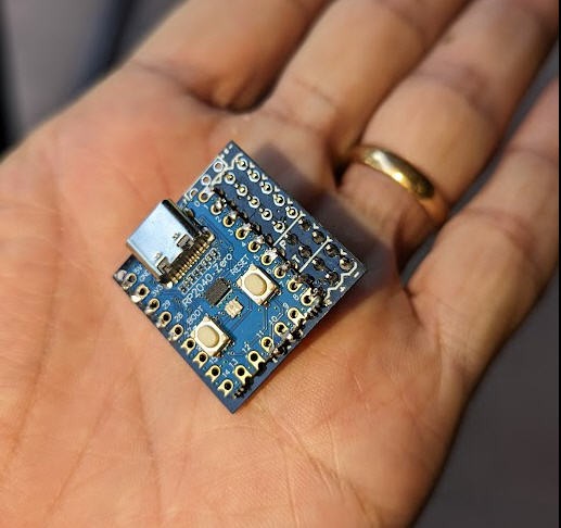
The final device looks more or less like a cube 28 mm x 30 mm x 18 mm
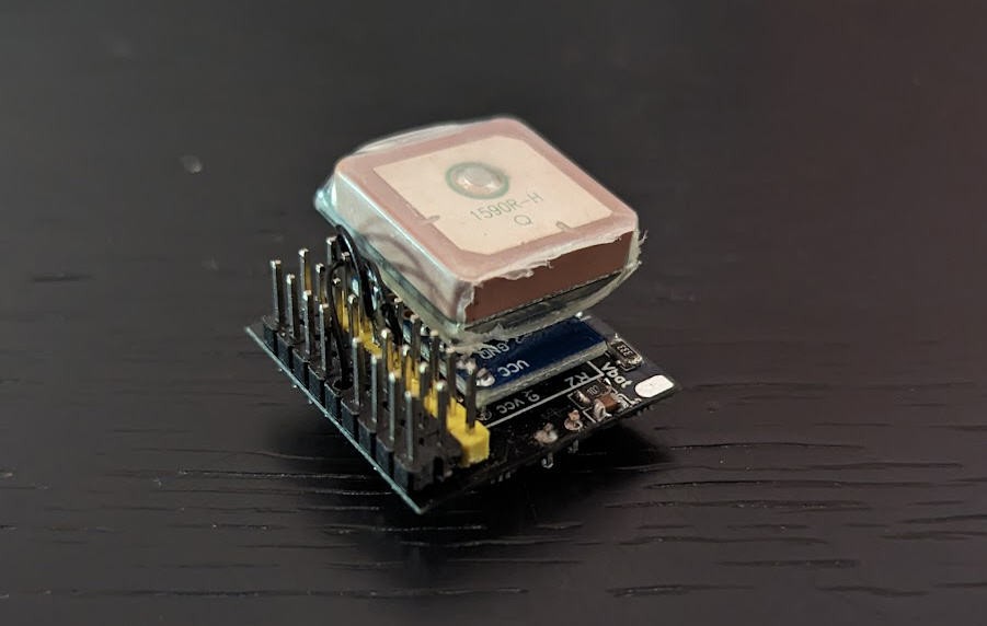
It could even be smaller with newest generations of GPS modules.
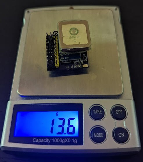
And it weights less than 14g
Optionnally (for french pilots) we will see how to modify a TX16s radio to incorporate a "remoteID" beacon in it.
This will be compliant with french regulations for drone identification.
Follow this project and you will be able to build yours, configure it and fly !
It is not exactly a new design, but rather an "integration project" of existing solutions. So credits will go to people who produced these open source solutions. They will be quoted in time!
Schematics
Schematics for this project cannot be simpler... it's basically just an integration of existing DIY modules !
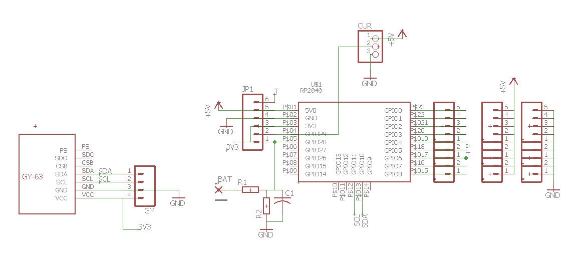
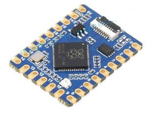
The heart is a Raspberry zero :
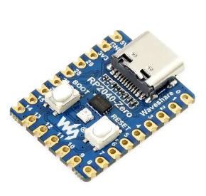
It could also be a raspberry tiny which is pin to pin compatible but doesn't have the USB connector.
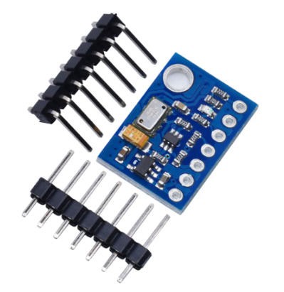
A GY-63 pressure sensor MS5611 is connected to the I2C port
Then a voltage divider is added to measure battery voltage.
- For lipo 3s pack R1 = 33k R2 = 10k
- For lipo 4s pack R1 = 47k R2 = 10k
And finally a few connectors are also added to connect sbus, Ibus and to allow extra channels to be accessible.
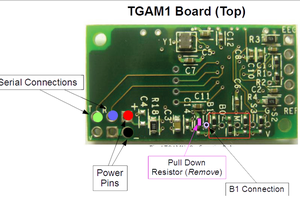
Power of the RP2040 is provided by these connectors. 5V is coming from the SBUS connector of the receiver which is itself connected to the 3 pins marked "T" (for Telemetry) obn the board.
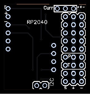
PCB
Aeropic routed this schematics to design of PCB. It's a very compact "mezzanine style" PCB
When assembled (without the GPS) it looks like this
The PCB was sponsored by PCBWay and you can order it on their site into my "shared projects"
Soldering is not totally simple as the GY-63 must be soldered first and the pin headers supporting it shouldn't protude too much on the other side where the RP2040 is soldered!
This video gives a step by step process for soldering the board but also for configuring it
Firmware
We will install OpenXsensor on this little board.
Mstrens made a fantastic job to allow OpenXsensor to run on Raspberry Zero boards. His project on github worths to spend a few hours reading : openXsensor (oXs) on RP2040 board
It could be a little intimidating at first glance. But here are the simplified steps to run your board with this firmware:
install the firmware
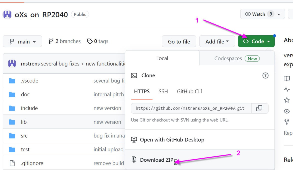
- download all the project from github
- click on "code" button
- then download zip
unzip all the file and open it until you see these files
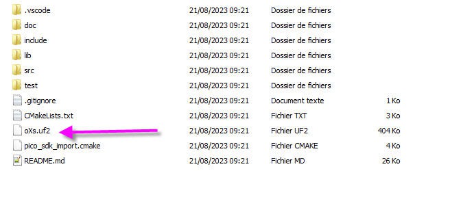
the oXs.uf2 is the binary firmware that you will have to flash into your RP2040
To do this, simply press the boot button on the RP2040 board and (while pressing) connect the board to your PC USB plug. Release the boot button and you should see a new USB disk poping up : this is the bootlader disk.
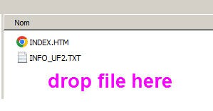
Simply drag and drop the oXs.uf2 file into this disk and your fimware will upload automatically!
When done you should see the red led flashing. OpenXsensor is running!
Configuring OpenXsensor
OpenXsensor is a very open firmware; it can work with custom boards (like ours) so you have to tell him which pin is used and for which kind of sensor!
This can be done using a serial terminal connected to the USB port of your RP2040.
It can be on a PC (arduino IDE serial port) or even on a smartphone.
I will show you this method as it is very handy...
Read more »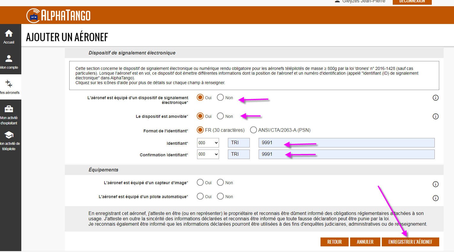
 Tom Meehan
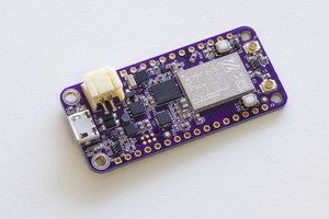
 Jared
Jared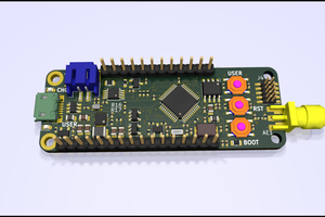
 Andy
Andy
 Gregory Meltzer