Close
0%
0%

PCB Lamp Workshop - Arduino Edition

Components and instructions to create your own touch-activated lamp, and learn about product design, hardware and firmware.

Public Chat
Similar projects worth following
This project page is part of the Introduction to Electronics Design workshop that uses the Arduino BLE Sense Rev2 development board.

This project is the Arduino edition of the Introduction to Electronics workshop. In this workshop we explore hardware manufacturing, firmware, and mechanical design with a hands-on approach.

The Hardware

There are two main hardware components: 

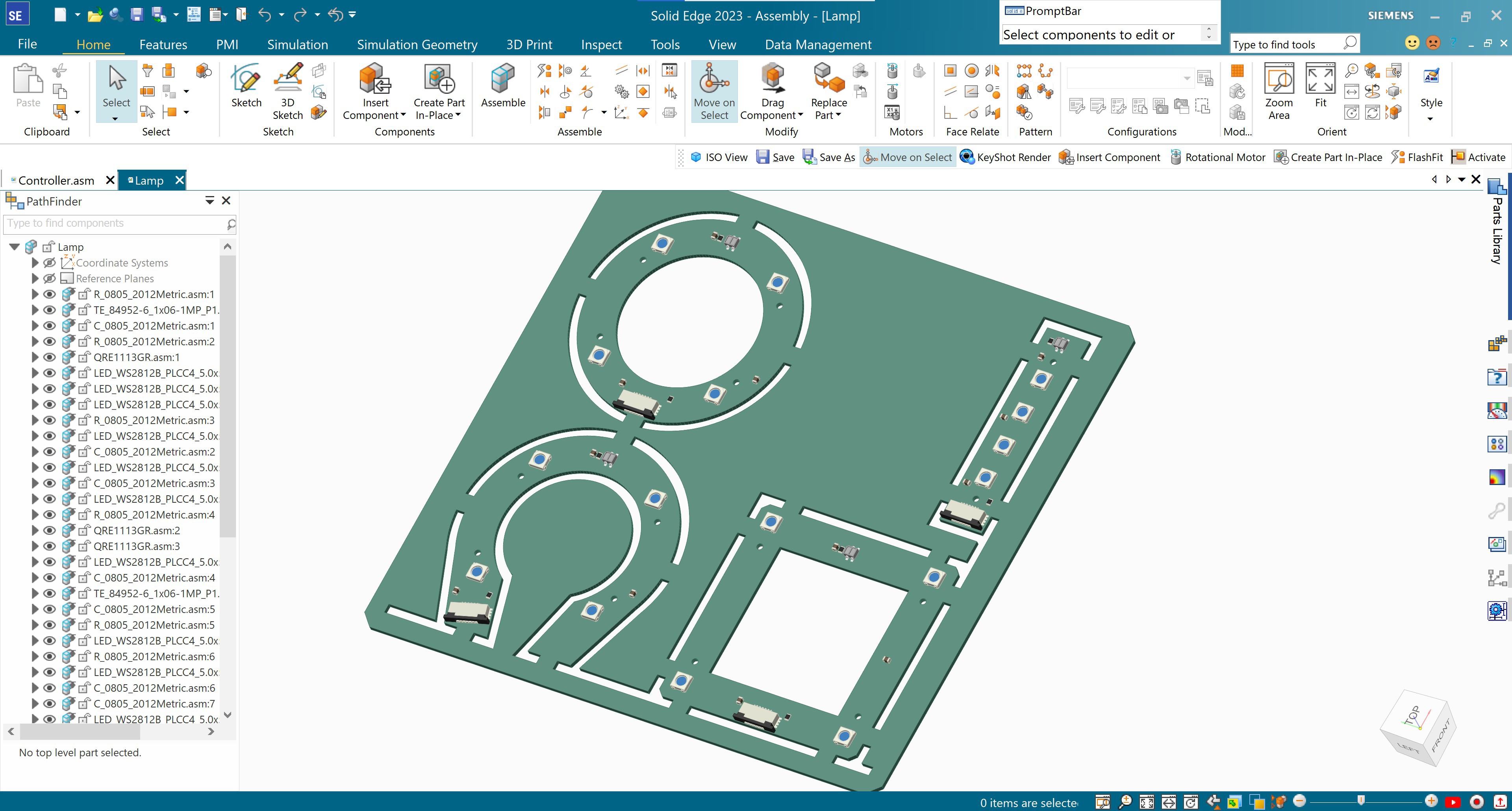
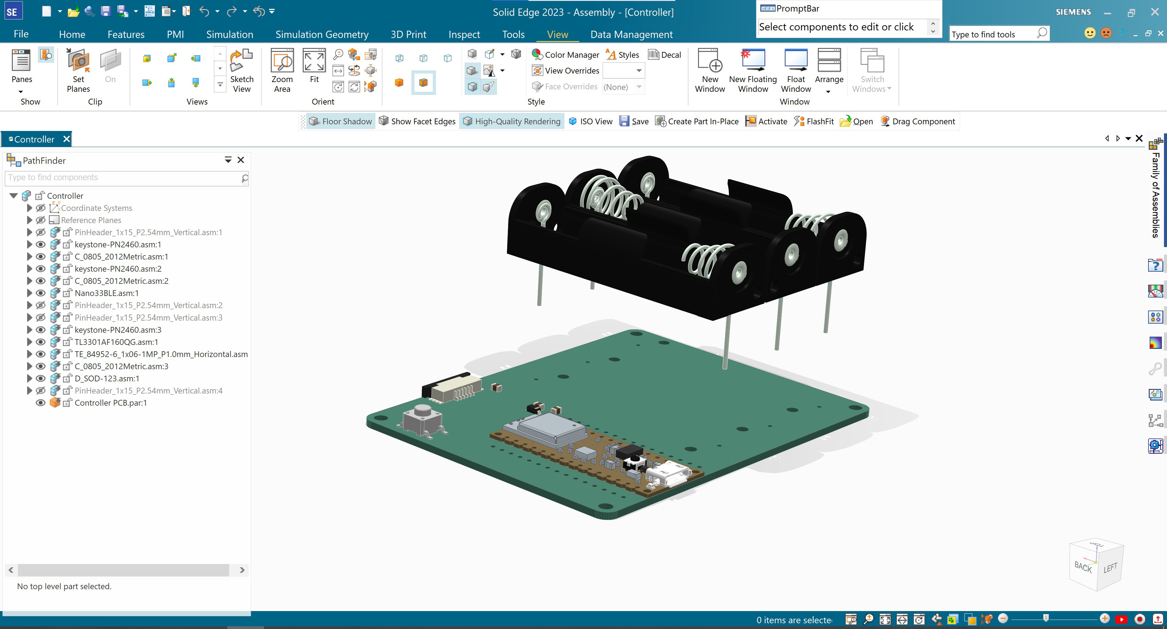
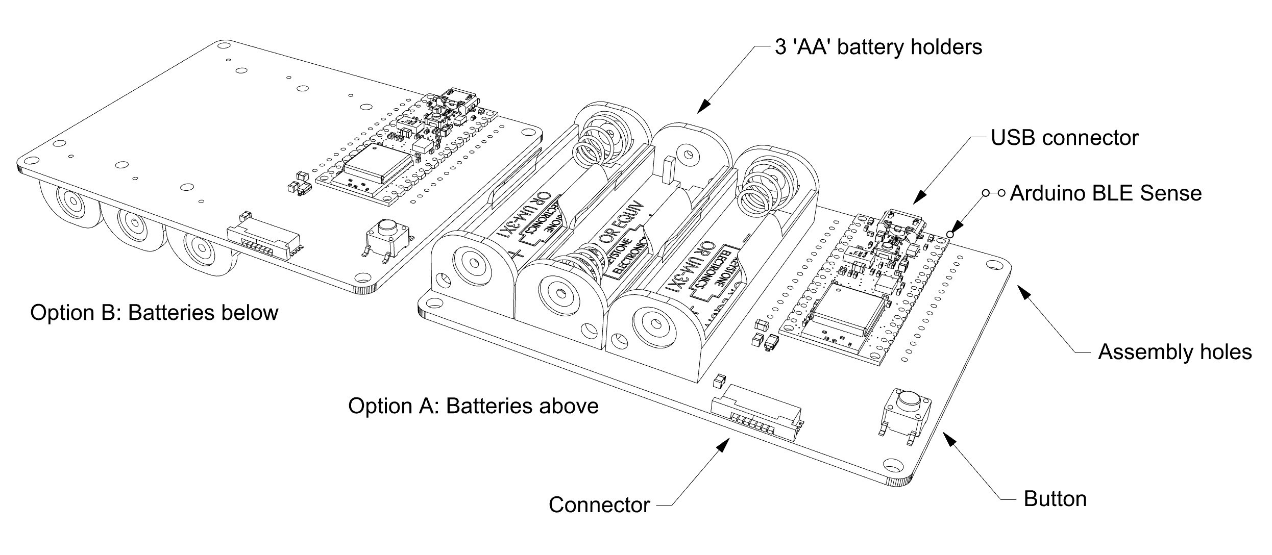
  • Controller Board: The "brains", power source, and sensors
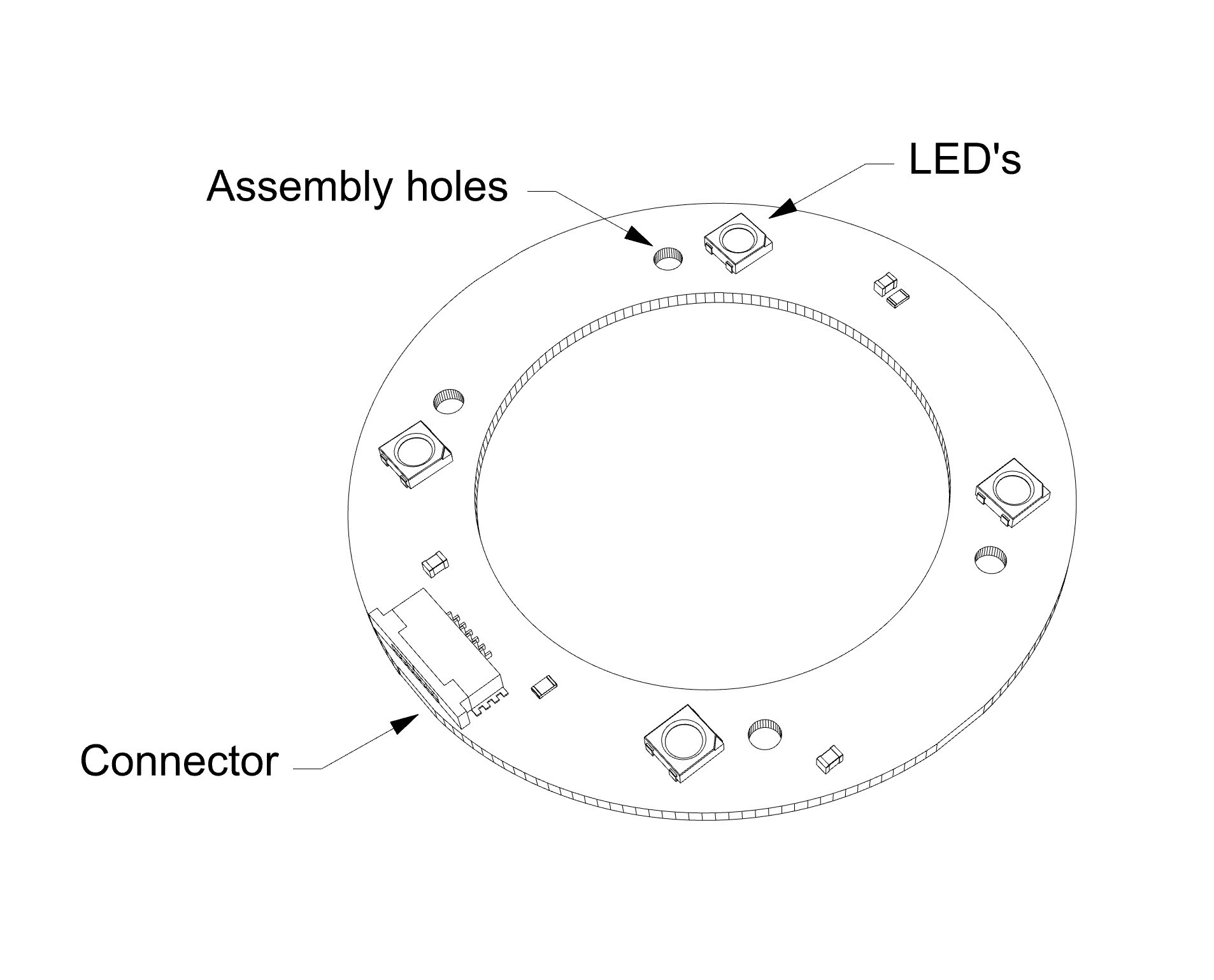
  • Lamp Board: the lighting element
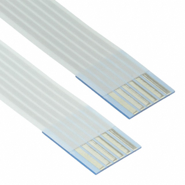
    • Ribbon cable to connect Base and Lamp (6" and 10")
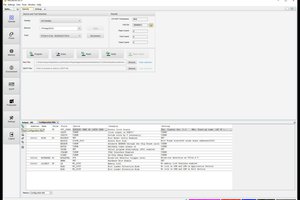
The Firmware

The Arduino Nano BLE 33 Sense Rev2 runs on C++, Arduino IDE, or Micro Python. For this project, we will be using Arduino IDE.
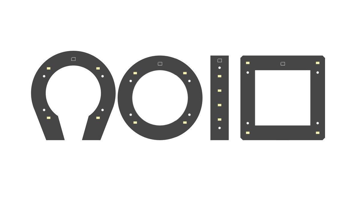
The Design

There are four different versions of the Lamp to choose from. They all include four LED's, and other components that will be detailed later. 

The Base is one standard design, and it can be placed as close or far from the lamp as needed. We will be using 6" or 10" long ribbon cables.

Please see Build Instructions for detailed information about downloads, templates, etc

ino - 2.74 kB - 04/06/2024 at 21:23

Download

PCBLampWorkshop_ArduinoEdition-SimpleAccelerometer.ino

Arduino sketch to change the color of the LEDs using the BLE's accelerometer

ino - 3.94 kB - 04/05/2024 at 00:52

Download

PCBLampWorkshop_ArduinoEdition-Microphone.ino

Arduino sketch to turn the LEDs on using the BLE's sound detector

ino - 3.90 kB - 04/05/2024 at 00:52

Download

ino - 4.23 kB - 04/05/2024 at 00:52

Download

PCBLampWorkshop_ArduinoEdition-ColorSensor.ino

Arduino sketch to change the color of the LEDs on the boards with the BLE's color sensor

ino - 2.09 kB - 04/05/2024 at 00:52

Download

View all 20 files

  • 1 × Controller Board Arduino Nano BLE 33 Sense Rev2 & Battery holders (3 'AA')
  • 1 × Lamp Board Four shapes available. Each one with four LED's and the same circuit design
  • 1 × Ribbon Cable 6" OR 10" CABLE (FFC/FPC 6POS 1MM)
  • 8 × M2 Hex nuts Optional depending on lamp design
  • 8 × M2 Screws Optional depending on lamp design

  • 1
    Overview

    Controller and Lamp are connected with a ribbon cable (see Data Sheet). There are two available cables: 6 and 10". Depending on your design, you may choose one or the other. 

    The same goes for the four Lamp Board shapes. All have the same components. Please choose the one that better fits your design concept. 

    There is only one Controller Board shape. this is where the BLE Sense and batteries are located. However, your design will inform where the battery holders are placed. Please do not solder the battery holders to the board until you have read all the remaining steps! There are a few important considerations to define first.

  • 2
    Controller Board

    The Controller Board has a few important components and attributes to be aware of when designing your Lamp project. 

    • The Arduino Nano 33 BLE Sense Rev2. This phenomenal development board is jam-packed with sensors and other goodies that will add new depths to this and future projects of yours. It is really recommended that you read a bit about its fantastic capabilities. More on that later. For now, we will mention that it comes with: Bluetooth, motion detection, microphone, proximity and gesture detection, barometric pressure detection, temperature and humidity sensors., micropython support, and it features a nRF52840 microcontroller.
    • 3 'AA' battery holders. Ideally, these should be easily reachable. Batteries may be rechargeable or non-rechargeable.
    • Ribbon cable connector. 
    • USB mini port. Your design will determine if this port has to be accessible at all times or not. However, we will use it to flash (upload) firmware to the microcontroller. 

    Assembly holes and precise dimensions can be found in the AI and 3D STEP files. 

         + + + IMPORTANT + + +

    Before soldering the battery holders and Arduino BLE Sense, take some time to define your design. Does it make more sense to put the batteries on the same side as the Arduino? Is it best to keep them separate?  

  • 3
    Lamp Board

    As mentioned earlier, all Lamp Boards have the same components. Here is a quick overview, before we go into more detail:

    • Four addressable RGB LED's. RGB means that they can cast Red, Green, Blue light, and everything in between. Addressable means that each one can be operated separately. 
    • Four assembly holes. 
    • One ribbon cable connector. This cable supplies power and sends and receives data to and from the Controller Board.

    Just like the Controller Board, assembly holes and precise dimensions can be found in the AI, and 3D STEP files. 

View all 8 instructions

Enjoy this project?

Share

Discussions

Similar Projects

Does this project spark your interest?

Become a member to follow this project and never miss any updates