Close
0%
0%

3D Printed Chiming Clock

A 3D printable clock that uses a train of marbles to strike the hours

Similar projects worth following
This is a 3D printed clock that strikes the hour with a train of marbles. As the minute hand makes a complete revolution it raises the appropriate number of marbles to be released at the top of the hour. When released, the train of marbles trips a hammer to strike a long tubular bell, generating a gong for each hour.

It was inspired by the many iterations of Clayton Boyer's wooden marble strike clocks you can find on YouTube. I really didn't want to cut out all the wooden parts, so I decided to design a version that could be 3D printed. Only a few parts need to be assembled from separate pieces, most parts will fit on a 300x300mm print bed.

A big plus to using a 3D printer for the parts, besides the obvious convenience, is that it allowed me to simplify a large number of complex assemblies into one piece parts. Another benefit to being 3D printed is that color scheme can mimic the wooden designs, or can be much more playful.

How the clock is supposed to work was made pretty clear from the videos that I found on YouTube. The whole mechanism is keyed off from the marble lift wheel that make one revolution per hour. 

  • As the wheel goes around it will pick up one marble from the bottom marble storage ramp ( in the slightly offset lead hole). Then the wheel will pick up all the marbles in the upper teeter totter accumulator ramp in sequence into the outer holes as they rotate past the ramp.
  •  As the holes in the lift wheel reach the top the marbles are allowed to exit onto a ramp at the back. The marbles roll down and around the ramp to stack up in the front of the clock at the trip arm's marble stop. 
  • As the minute hand approaches the 12 o'clock position, the cam follower on the trip arm is activated so that the marble stop on the trip arm allows a marble past to be held back by the secondary stop on the trip arm. 
  • When the minute hand reaches the 12 o'clock position, the trip arm cam follower is allowed to reset, letting the advanced marble proceed down the ramp and restraining the rest of the marbles in the train. 
  • As the released marble rolls down the ramp it will again depress the trip arm to allow the next marble to be advanced to the secondary stop position.
  • When the marble exits the ramp it will ring the gong and release the advanced marble to proceed down the ramp to continue the eventual release of all the marbles in the train. The length and angle of the ramp greats the delay between the striking of the gong.
  • After each marble triggers a gong strike it is directed into the upper teeter totter accumulator ramp. The teeter totter is balance so that it remains angled down towards the lift wheel until the 12th marble is added to the teeter totter.
  • When the 12th marble is added the teeter totter tips over to release all 12 accumulated marbles to be directed to the bottom storage ramp, thus restarting the process for the next 12 hours.

Tipping ramps are used in a lot of marble kinetic sculptures, but combining it with the lift wheel creates a mechanical adder/accumulator with a reset. 

The time keeping portion off the clock is regulated by a 1 meter (1 second) pendulum and a Graham Yoke escape wheel with 30 teeth, resulting in one revolution of the escape wheel per minute. A drive train reduces the escape wheel's revolutions by 60 to rotate the lift wheel (and the minute hand) once per hour. A second 12 to 1 drive train hangs off the axle off the lift wheel to reduce its revolutions to once per 12 hours for the hour hand. The second drive train is free hanging and uses a weight to keep it vertical.

Simple huh?

I just needed to create a version that could be 3D printed, not to difficult right?

Time to fire up FreeCAD.

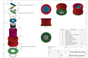
You can find the all the FreeCAD files on GRABCAD.


Armed with the marble size (16mm) and the printer bed size (300x300mm) I set about designing the clock. After iterating through various design choices I've come up with a design that I think has a good chance of working, I just need to print out a few test pieces to see if my design choices will work. Most notably the Graham Escapement, the Teeter Totter rail, and the marble lift.

Over all the design uses 5mm axles and flanged F695 bearing for the pivot points except for the lift wheel which uses an 8mm axle and 608 bearings. M3, M4, and M5 thermal inserts along with appropriate screws are used to fasten the various pieces together. Parts were designed to be printed with minimal or no supports (I really don't like using printing supports unless I have to).

A few of the more interesting design elements are as follows:

Some of the YouTube videos showed the marble lift wheel being manually rotated (to show how the mechanism worked) without the pendulum, nor the yoke swinging. This indicates that the Graham Escapement they used has a position that allows the escape wheel to freely rotate. I don't like that option so the...

Read more »

3D Printed Chiming Clock Ver II - STL files.zip

These are the STL files for the new version of the 3D printed chiming clock that include the Escape Wheel with thin pin style teeth.

x-zip-compressed - 37.86 MB - 11/11/2023 at 01:49

Download

3D Printed Chiming Clock Ver II - STEP files.zip

These are the STEP files for the new version of the 3D printed chiming clock that include the Escape Wheel with thin pin style teeth.

x-zip-compressed - 47.11 MB - 11/11/2023 at 01:49

Download

3D Printed Chiming Clock - STL files.zip

STL files for the 3D Printed Chiming Clock

application/x-zip-compressed - 37.92 MB - 11/03/2023 at 01:03

Download

3D Printed Chiming Clock - STEP files.zip

STEP files for the 3D Printed Chiming Clock

x-zip-compressed - 46.79 MB - 11/03/2023 at 01:04

Download

FreeCAD Files Ver II.zip.001

Part 1 of 4 for a ZIP file of all the FreeCAD files made with 7zip.

001 - 35.00 MB - 11/11/2023 at 18:42

Download

View all 8 files

  • 65 × 16mm Marble
  • 2 × 1kg Spool of PLA filament
  • 1 × 8mm Shaft - 150mm long
  • 1 × 5mm Shaft - 500mm long
  • 38 × F695 5mm Flanged Bearing

View all 35 components

  • Third Time is a Charm?

    wooddragon4811/11/2023 at 01:17 0 comments

    Okay the second version of the Escape Wheel was better than the first, but still was not a complete success. This time it was not possible to adjust the pallets to prevent the escape wheel from free running, or jamming. And of course that means that I've a made another version to test. This time around the teeth on the Escape Wheel are more like spokes than teeth. This design allows the pallets to be in full blocking mode for the next tooth before the current tooth finishes pushing the opposite pallet out of the way. I did however have to add 20mm to the diameter of the Escape Wheel in order to thick enough (4mm) teeth with sufficient space between the teeth.

    Upper Pallet detail.

    Lower Pallet detail.

    Hopefully this version will work better.

  • Well It almost worked

    wooddragon4811/04/2023 at 21:23 0 comments

    I printed a copy of the Escape Wheel and the Graham Yoke to test how well it would work. Well it mostly worked, but would occasionally hang up, and was quite rough in spots. So I decided to go back to basics and redesign both the Yoke and the Escape Wheel. This version of the Yoke has adjustable pallets, and the Escape Wheel has a negative rake on the teeth to provide relief to the pallets as they over travel. With regards to the Yoke over travel, this design allows for three to four degrees of over travel in each direction. As this a Graham Yoke the escape wheel is held stationary while the Yoke over travels with the pallets just sliding along the tip of the Escape Wheel tooth. This hopefully means that I can sand the striking and sliding surfaces along with the tips of the Escape Wheel teeth to make the operation smooth and quite. With adjustable pallets it is possible to setup the Yoke so that the inactive pallet is in position to block the next tooth on the Escape wheel just before the impulse portion of the cycle is finished.

    To help visualize and verify the design I did a quickie Python script to animate the escape operation

    Upper pallet detail.

    Lower Pallet detail.

    Now I just need to print the new parts and see how well it works. I will up load the new design to replace the not so good ones.

    And Just because I think It looks cool, here is the animation in an isometric view.

    I updated the ZIP file to have the new Yoke and Escape Wheel, a few changed files that were fixed to make them easier to print, and the Back Frame parts that need to change to accommodate the new thicker Yoke design.

    .

  • Christmas is Coming

    wooddragon4811/03/2023 at 02:12 0 comments

    I added a full collection of STL and STEP files and a link to a GRABCAD model that has all of the FreeCAD files as well. I am planning on making one for a Christmas present, and I thought that others might want to do the same so I made sure that the current version of my design is available. If I nee to make changes I will post them as needed.

View all 3 project logs

Enjoy this project?

Share

Discussions

Similar Projects

Does this project spark your interest?

Become a member to follow this project and never miss any updates