CentyLab
-
Functional prototype is here
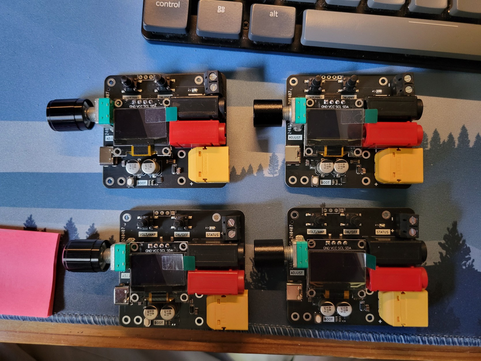
04/19/2024 at 21:27 • 0 commentsAfter a long wait from our PCB vendor, the boards are already here. This is the first batch to confirm our wiring, mechanical test, electrical and thermal performance.
It is good news that the wiring is all good. The board boots up with some code modification from the previous design. We can work more on the mechanical design but overall it will FIT inside a case!
The port layout works a bit better than we expected. The buttons' spring force and height are just right. The screen height is low enough not to shadow the button labels.
The initial thermal test shows that the output switch selected is good for 3A continuous. We will also move the location of the status LED so that it can be used at night without being too bright.
The next step for these 4 boards is to design a case for them. Let us know if you want to be our beta user and explore the application with USB PPS!
![]()
-
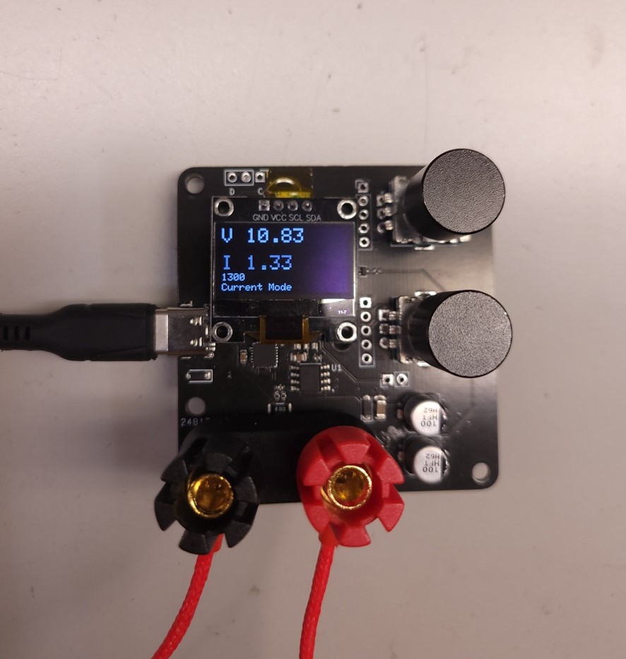
Current mode is working
03/02/2024 at 00:22 • 0 commentsIt requires some modification to the AP33772 Library but it seems like the current limit is working on our device.
Here you can see the current limit (small font) is at 1.3A and we are reading 1.32A. The voltage will change when you are in current limit mode. During this mode, the voltage encoder knob will not react if you increase the voltage as the voltage is capped by the current.
![]()
-
Debug current/voltage measurement
02/27/2024 at 04:58 • 0 commentsThe prototype version of PocketPD utilizes a sense resistor of 10mOhm to measure the current reading of the load. Here is the configuration for V.Prototype:
![]()
The power goes directly from USB-C VBUS, and passes through the sense resistor, thru the PMOS output switch to the banana jack terminals.
Issue: VBUS reading is higher than VOUT, more than expected. There must be more voltage drop somewhere.
Current (A) VBUS voltage (V) Vdrop across PMOS (V) Calculated Ron 0.40 3.30 0.027 68mOhm 1.00 8.14 0.068 68mOhm 1.80 15.0 0.126 68mOhm It was a bit surprising that Ron is consistent across multiple input voltages as Vgs and Ron are dependent on each other. Further investigation is needed
Conclusion: The resistance of PMOS (68mOhm) is higher than expected (18mOhm) which causes the discrepancy between the OLED measured and the Banana jack output.
Solution:
- Use the known resistance drop across the PMOS. Calculate the expected voltage drop with current. Display the adjusted VBUS value
- Move the current sensing to just before the banana jack. This will take care if there need to be component changes on PMOS due to part shortage or part upgrade.
But !... The current reading is now calibrated. We are getting the correct amperage report through the Rsense resistor!
PocketPD - USB-C Portable Bench Power Supply
Leveraging the Programmable Power Supply (PPS) of USB PD 3.0 and 3.1 to make an ultra-compact bench power supply