Currently on-going, goal is to have the MVP by 30/04/2024.
If you're interested in following the project, take a look at the logs.
The goal is to create a skate moving erratically
Already have an account? Log in.
To make the experience fit your profile, pick a username and tell us what interests you.
Currently on-going, goal is to have the MVP by 30/04/2024.
If you're interested in following the project, take a look at the logs.

25/04/2024
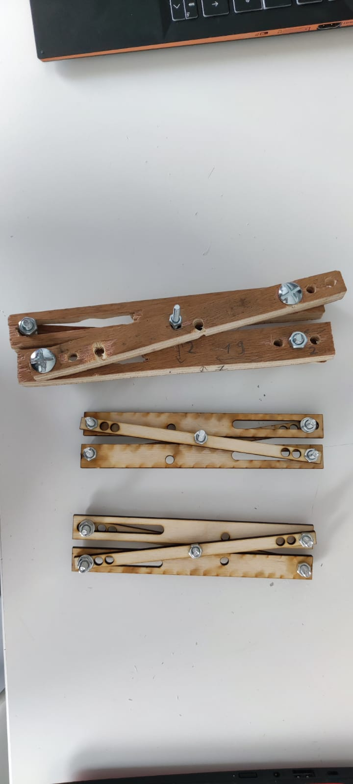
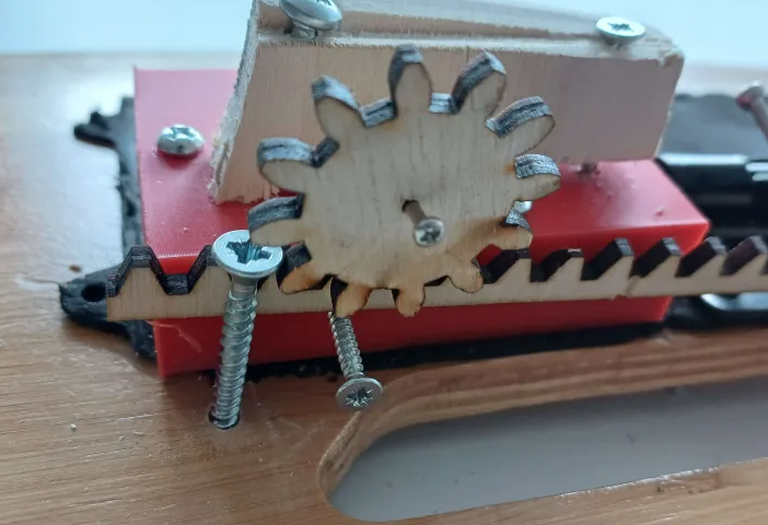
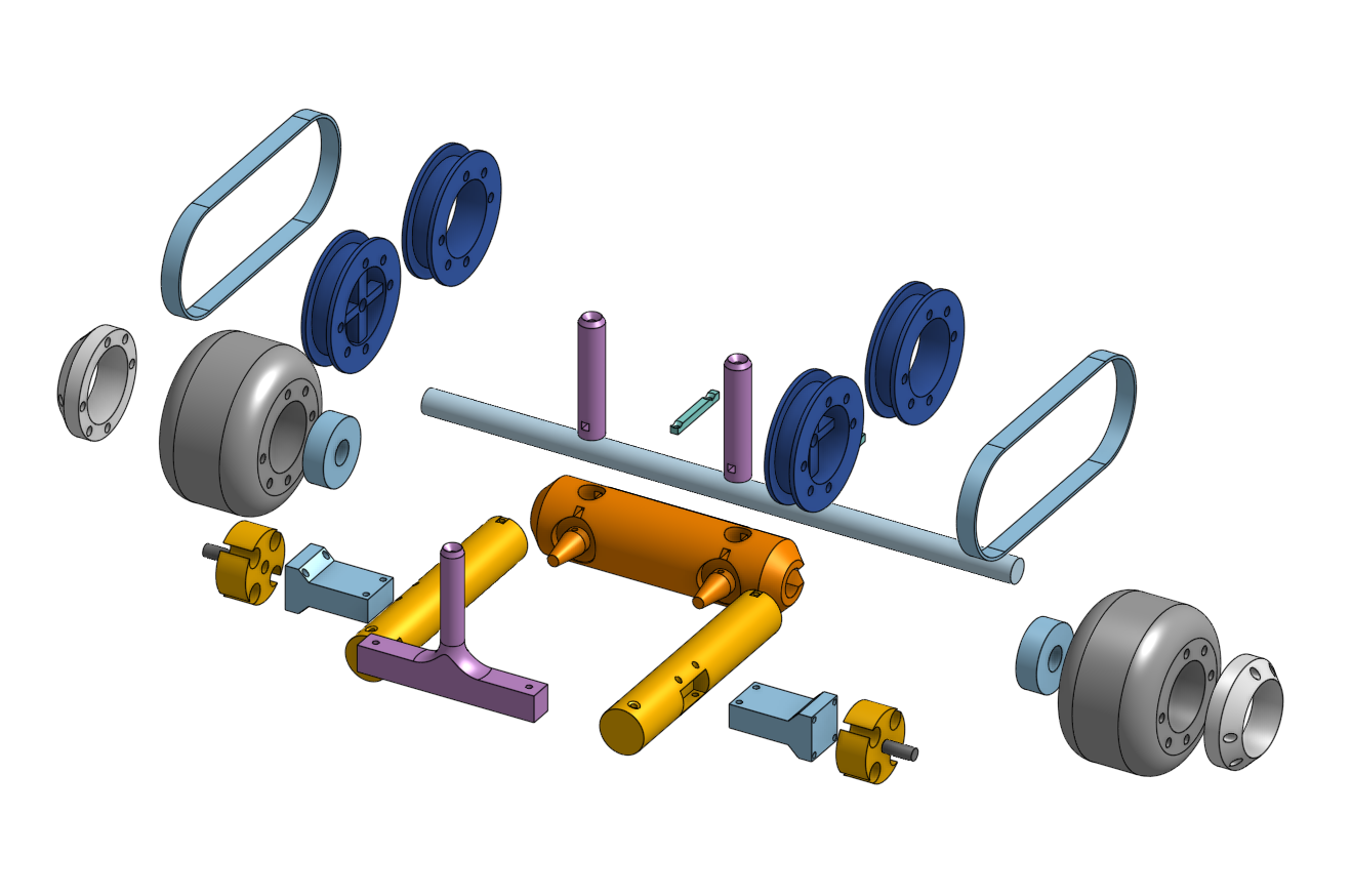
Since we now have access to 3D printer and laser cutter alike, we made a more refined version of our lifter mechanism (and it's accompanying gears) as well as the housing for the definitely-not-a-gun bolt action.
Comparaison with the prototype lifter:
We mounted the new version of the lifter on a test-bed that will then be attached to the skateboard. This allow for easy access and testing. It has a lot less friction than the saw-made one but since it's thinner we are having some concern that you could bend and break laterally.
We anticipated this problem and that's why there is two set of lifter, we could double them to reinforce the structure. But this cause too much friction between and the part, meaning the second set will act as spare part for now.
Otherwise it's working fine, we 3D printed an additional small part that will act as an anchor for the lifter. (Here seen in black.)
All bolt are M2 by 12mm.
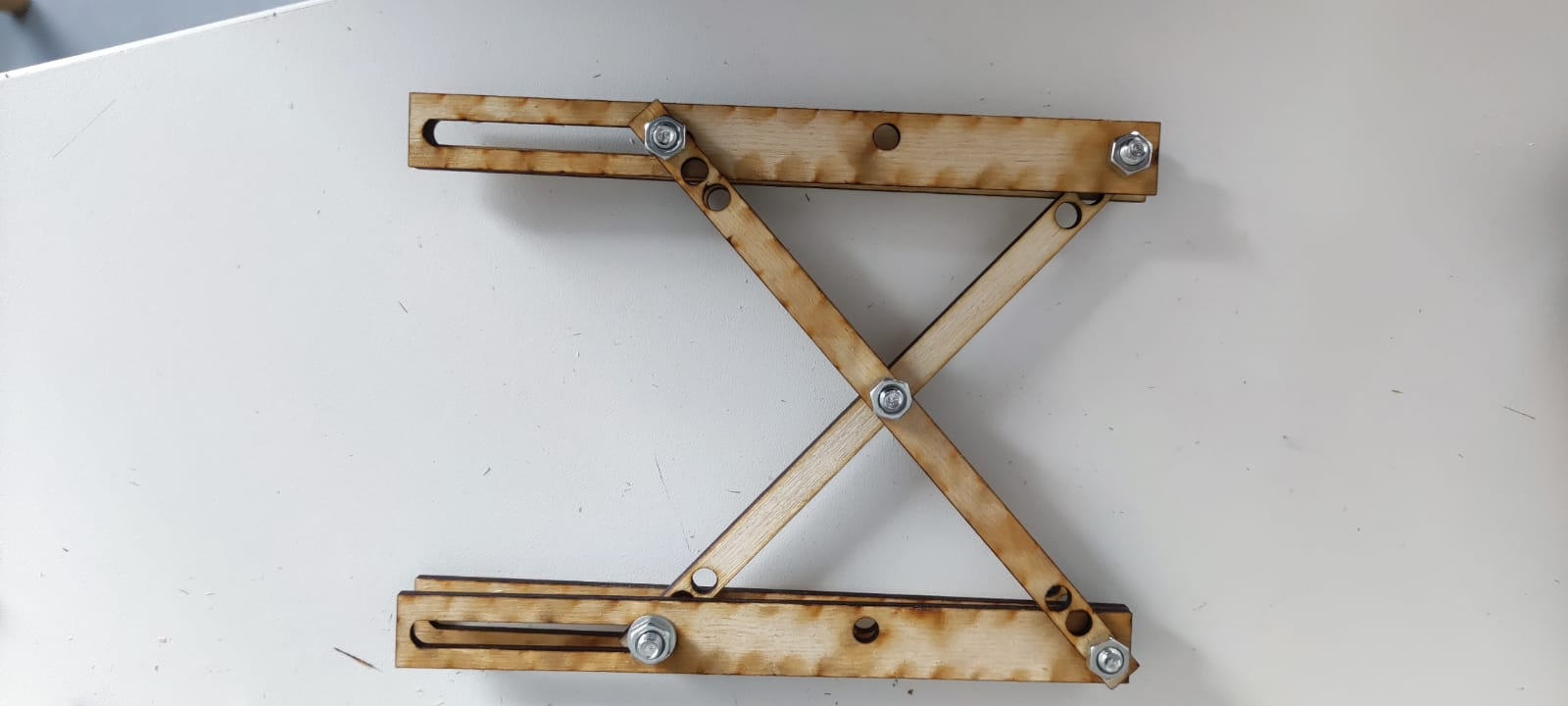
Showcase of the "double" arrangement.
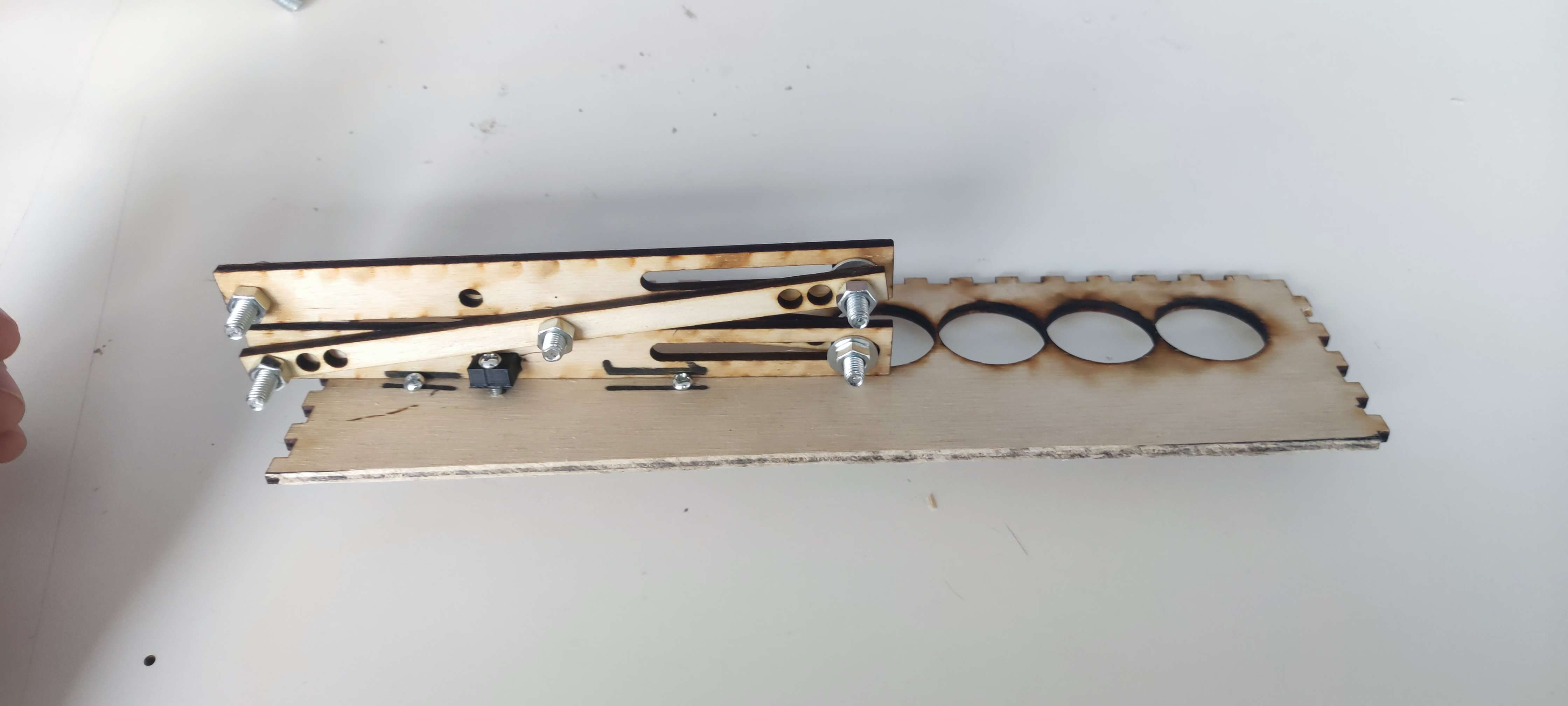
We then mounted the gas-propulsion part of the skateboard with the planned layout with the exception of the screwdriver that was replaced with a smaller and shorter bolt. We used a 80*8mm compressive spring that can reach a force of 2kg, more than enough for our need. It's house in the bottom red square and push against the barrel bolt.
And successfully tested it. This was a low-power test.
While the system is technically working, it's not working as good as we wanted it to be. Probably due to internal design of the gas chamber to avoid catastrophic leak, even if engaged, the gas chamber will only realise it's content in small burst and not a fast and continuous burn like we expected.
We may switch to Co2 cartridges which have the desired effect and are much more powerful in the future but single-use.
26/04/2024
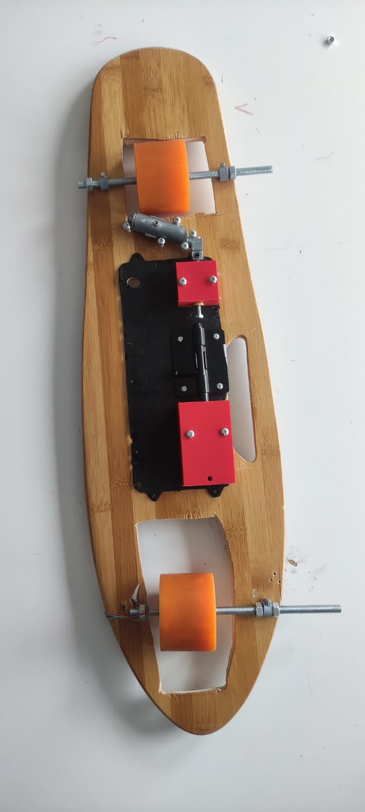
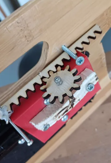
We installed the lifter mechanism on the skateboard after reducing the size of the test-bed.
Then we added the home-made linear actuator with a placeholder for where a future step motor will be to rotate the gear and create horizontal movement.
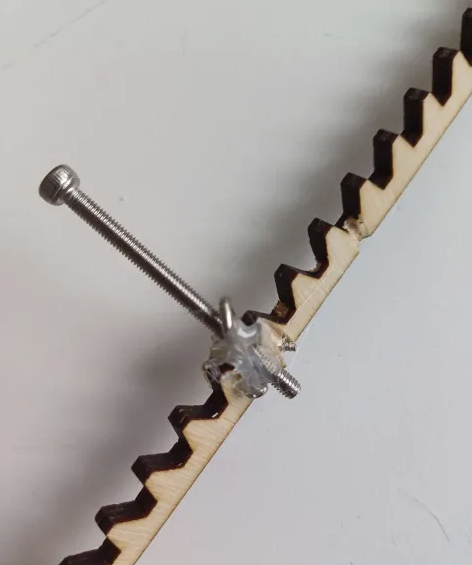
Further down the rack gear we have a twisted screw holding a long bolt whose just is to push the bolt and engage the gas-mechanism. If placed correctly, this will only happen when the lifter is fully extended.
29/04/2024
We realised the motor place-holder and the gear were too tall and touching the ground while the skateboard was moving. We needed to reduce both their size and did just that.
But the lowering of the gear necessitated to lower the rack level, and since the lifter bolt that fit in the rack is slightly elevated due to the test bed and the thickness of the lifter itself, meant it would no longer move the lifter reliably.
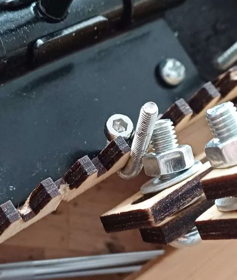
To solve this issue, another twisted bolt (made by securing one end and slamming the other with a hammer) now act as a hook. This work even better than before since the connexion between the two is sturdier than simply insetting the bolt in the rack.
We used to opportunity to reinforced the gear and motor-place-holder connexion with a M2*35 bolt instead of the thinnest screw we could find.
We used a piece of 3D print waste as structure to install the motor-wheel in contact to the rear wheel. Hopefully, this should transmit enough movement for the skate to be able to move while flipped.
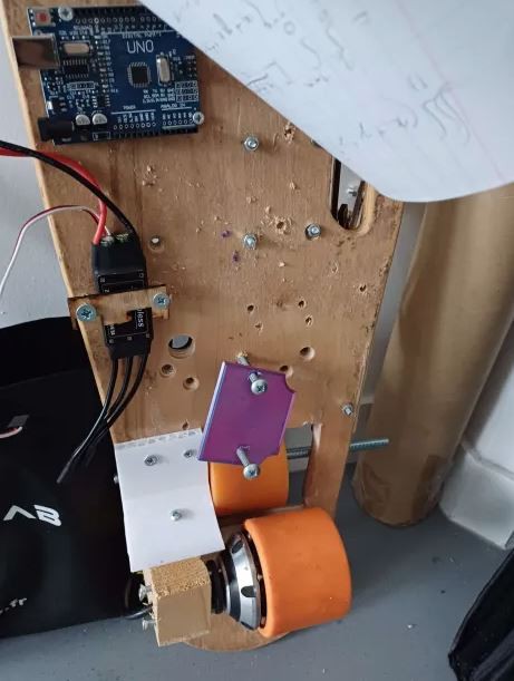
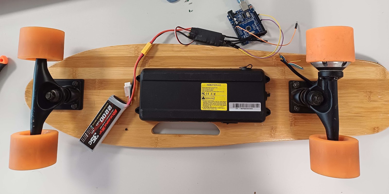
Other electronical components such as the ESC, the Arduino and a battery holder (here empty since the picture was taken before storage and Li-po should be kept in a fire-proof container) were added to the top of the skateboard using similar discarded materials and screws.
To-do: Make a transmitter fixation on the skateboard...
Read more »09/04/2024
Removing how skateboard "skin" was necessary to remove all the screws and components currently attached.
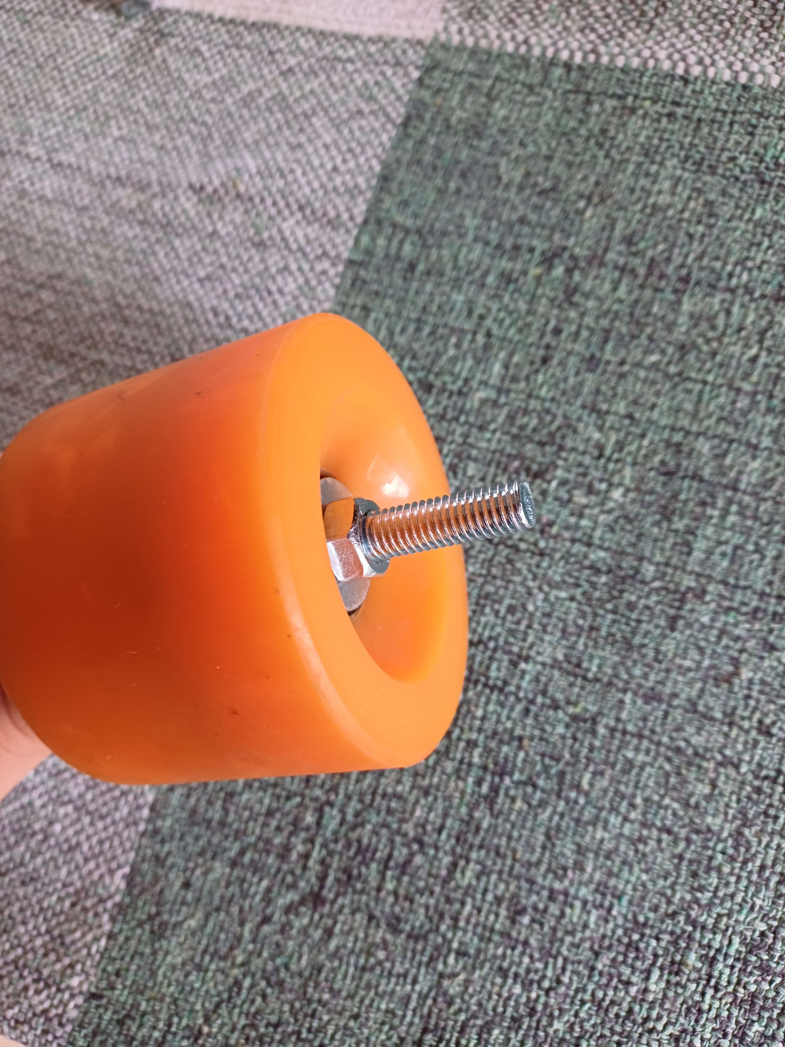
Here is a picture of the disassembled board, down up.
The main issue come from the motor section, in theory it's only held by three screw with hex socket. But for two of those, the hex is more of a circle. Removing of said screw was made harder by the very tight grip it seem to have been manufactured with/somehow strange other factor due to it's long time in storage, and a position that make access hard due to the hanger being in the way of the potential Allen key.
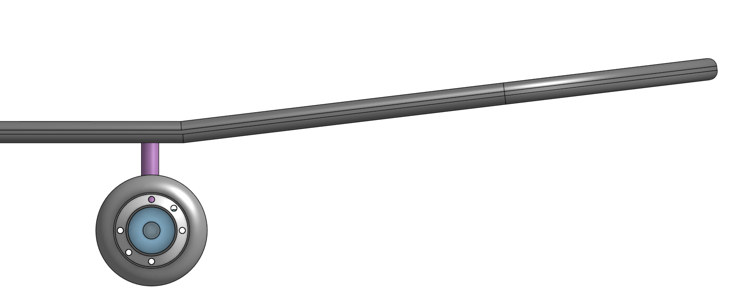
Due to theses factor and the fact that hanger aren't necessary or part of the project, since the wheels will need to be place on board level to be able to touch the ground even upside down as showed here:
With hanger:
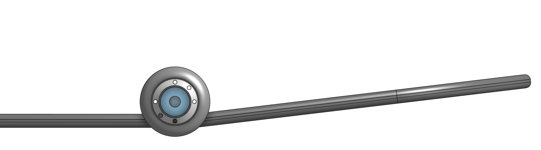
Without hanger (axis going through the board or directly on it :
Neither are at scale since the board 3D model isn't accurate and we wheel model is outdated.
Thus:
We cut the hanger.
Removing those circle-screw is still going to be hard, we tried to make a cut in them to insert a flat screwdriver with no avail.
It's also possible to forgot about this problem as long as the hanger still attached to the motor is attached to the board.
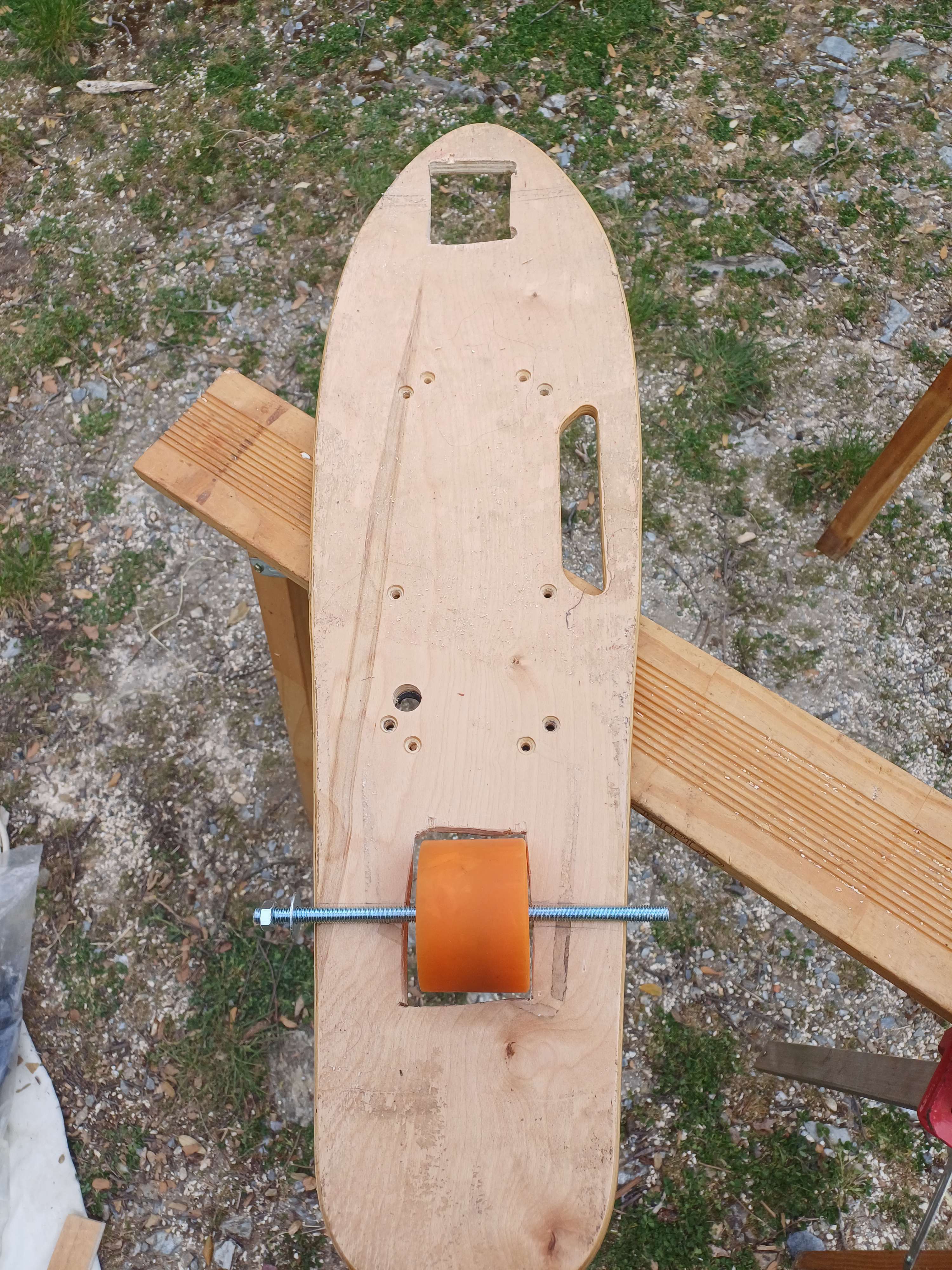
16/04/2024
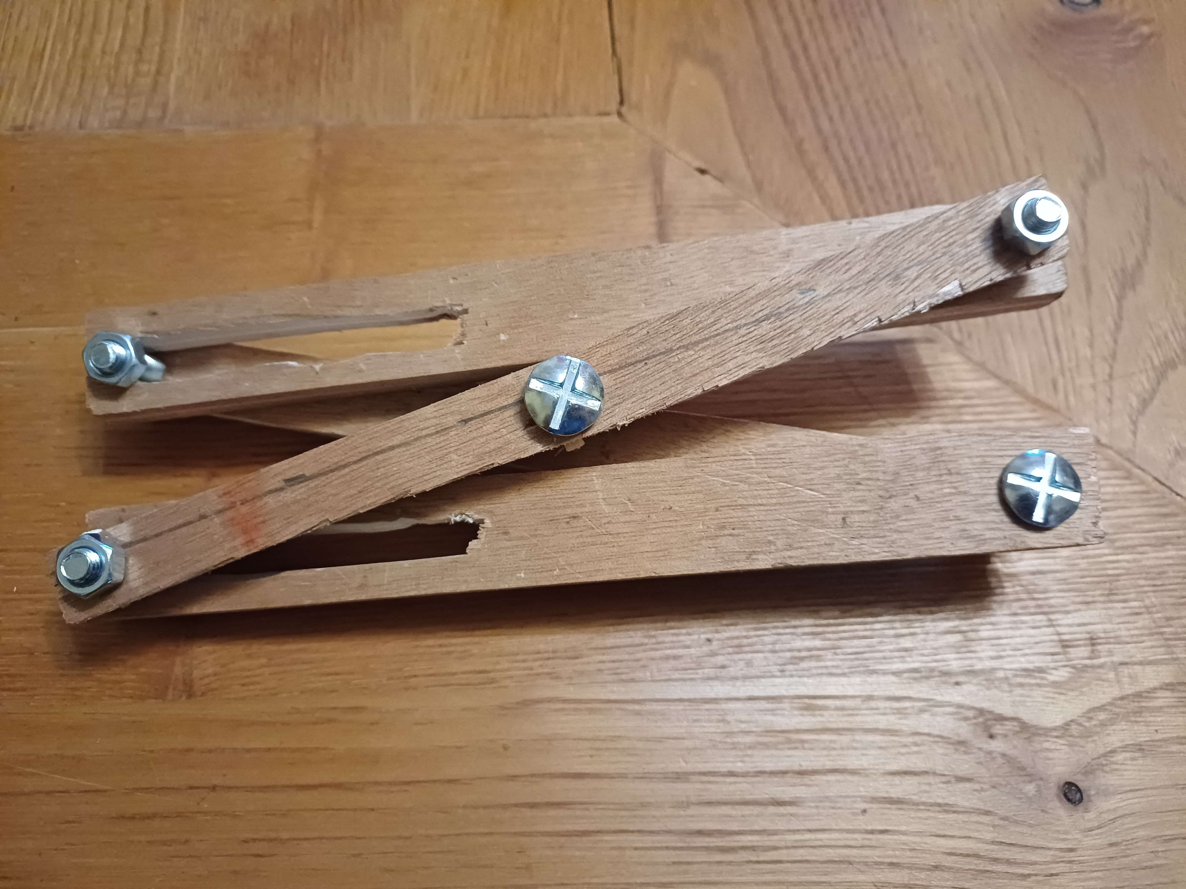
Printed (Laser-cut would have been easier but machine wasn't available) a pattern to cut wood to make the following system to lift one side of the skateboard.
Pattern:
Second:
Also bought 20cm beam that will be used as axle.
Wheels can be maintained in the same position while still be allowed to spin.
Will cut the board place the wheels along the center of the board and try to free the motor from it's wheeled prison.
17/04/2024
Was able to make the lifting mechanism but making gears by hands (and electrics tools) is not easy. Will probably wait for laser cutting to be available.
We found a way to finally free the motor, a steady pliers and a drill were required.
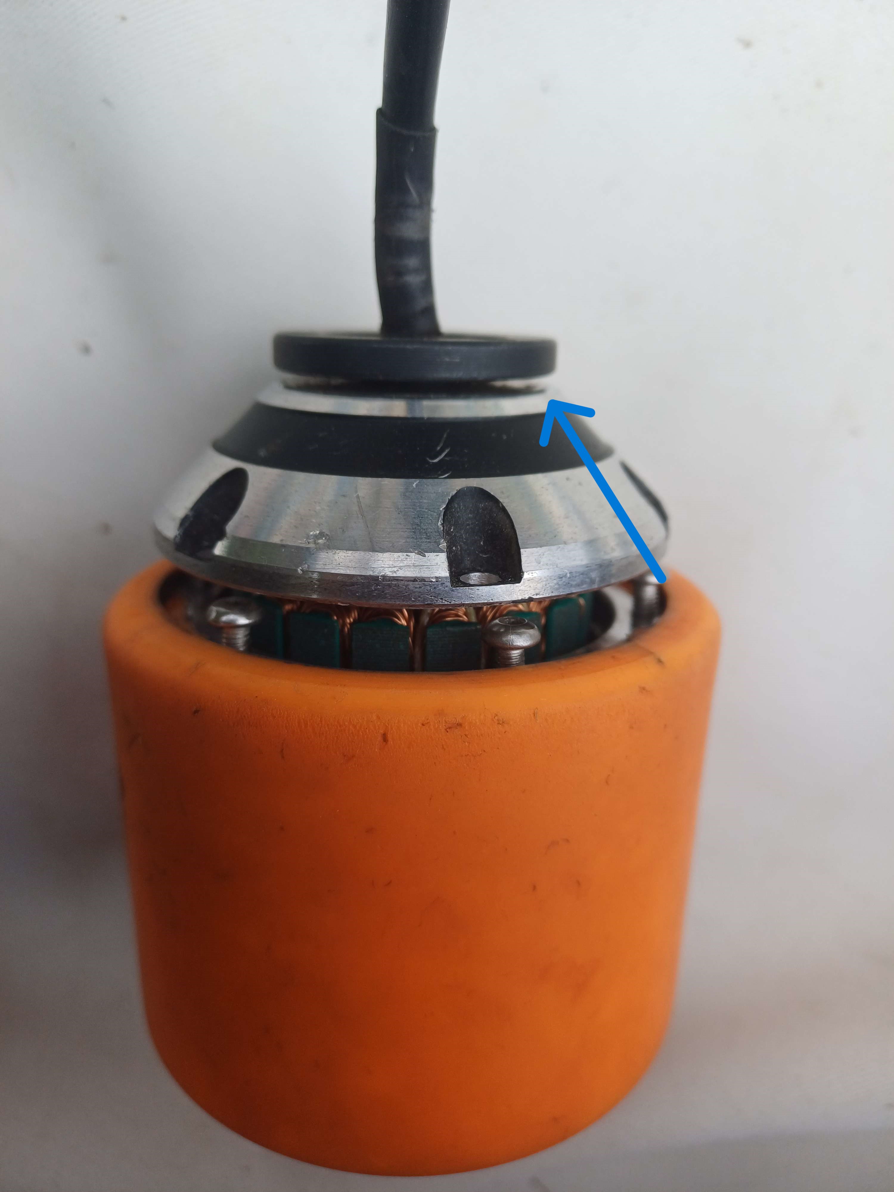
The internal access main benefit was the possibility to drill a hole through the ball bearing to allow the axle to be installed creating a steady connection between the motor-wheel and the main body, with a bit of tinkering maybe offsetting the cable would permit having symmetric axle (it can't be a singular one since the motor is in the way.)
"Worst case" scenario was the impossibility to remove the cable and needing to enlarge one of the hole that was previously housing the problematic screw, putting an offset axle through it and accepting the less symmetric but working solution. The offset wouldn't affect the movement since its connected to the stator, which doesn't move.
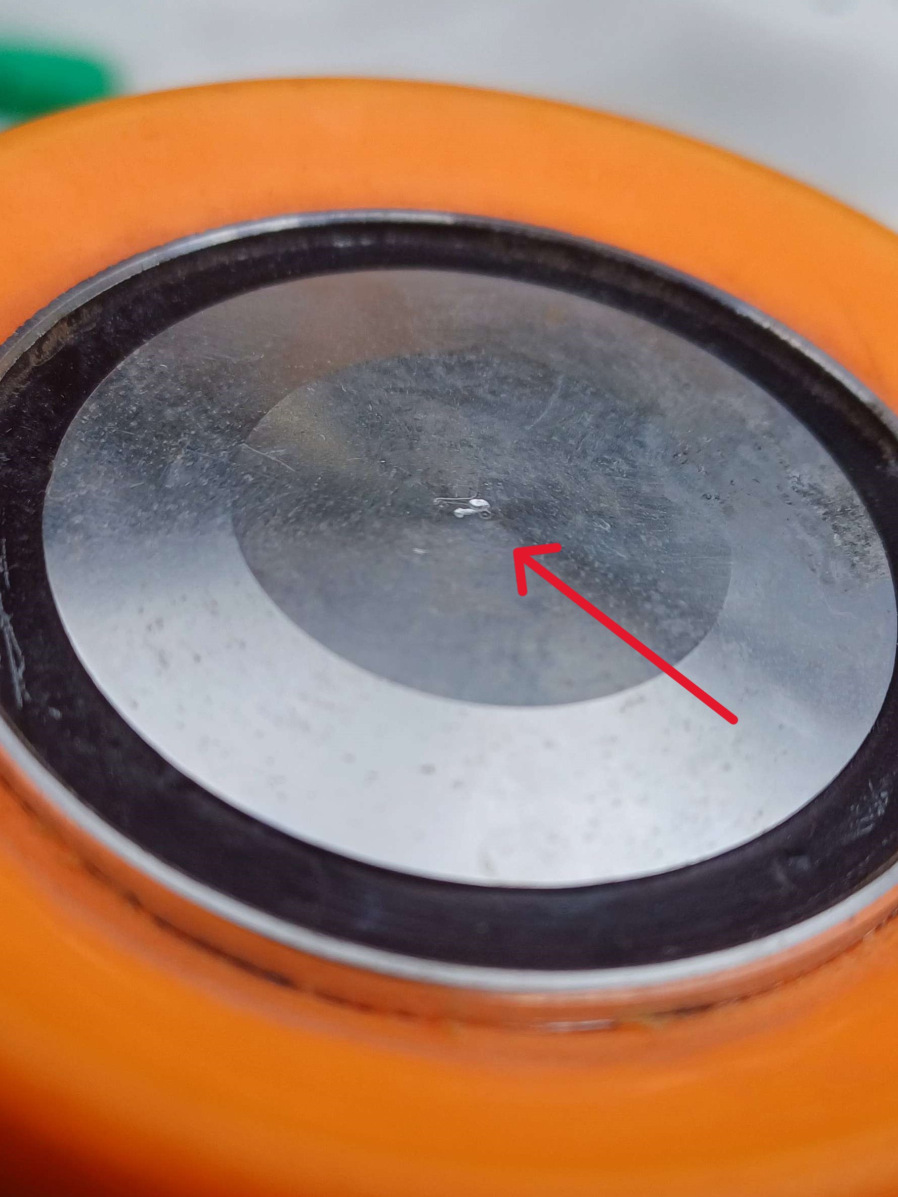
But really proved worst than the worst case, the casing (on either side) is harder than the metal drill we have. Here is a picture of the outside part of the casing as a showcase.
Also the case for this part (see blue arrow), preventing a clean body-axle-motor connection since even the currents bores can't be enlarged.
We will either need to find really longs screws (probably a bit weak, especially if it's only on one side of the wheel and the diameter is quite small), weld the axle (sub optimal for the safety of my fingers and above my pay-grade), glue (too weak) or find a better drill (may be hard depending on the material).
The idea of putting the axle through the body was abandoned due to risk of permanent structural damage to the skateboard, thickness of body is only a few mm greater than axle width. We will install it on the board instead, see pictures as reference.
Wheels will still be able to touch the ground on both side. Axle could be maintained using small wood blocs but we should be able to buy something cleaner for cheap tomorrow. We will also need to enlarge the...
Read more »We acquired the skateboard today, the battery is dead but we can salvage the structure and the brush less motor that is still attached.
We checked if the battery and ESC worked by doing a test with a small brushless motor and using this tutorial.
https://arduino.blaisepascal.fr/controler-un-moteur-brushless/
then with the one on the skateboard. We could solder everything to technically have a pretty bare-bone electric skateboard.
We will probably drill holes through the skateboard to have the wheel having clearance on top and bottom, allowing it to be on its back and still working. Omni-wheels are also considered to create more chaos.
Before changing the scope from "building our own hanger and structure" to "use the one available" we finished the 3D model to be used with the old wheel. It won't be used but I'll still post it since it was a bit of work.
26/03/2024
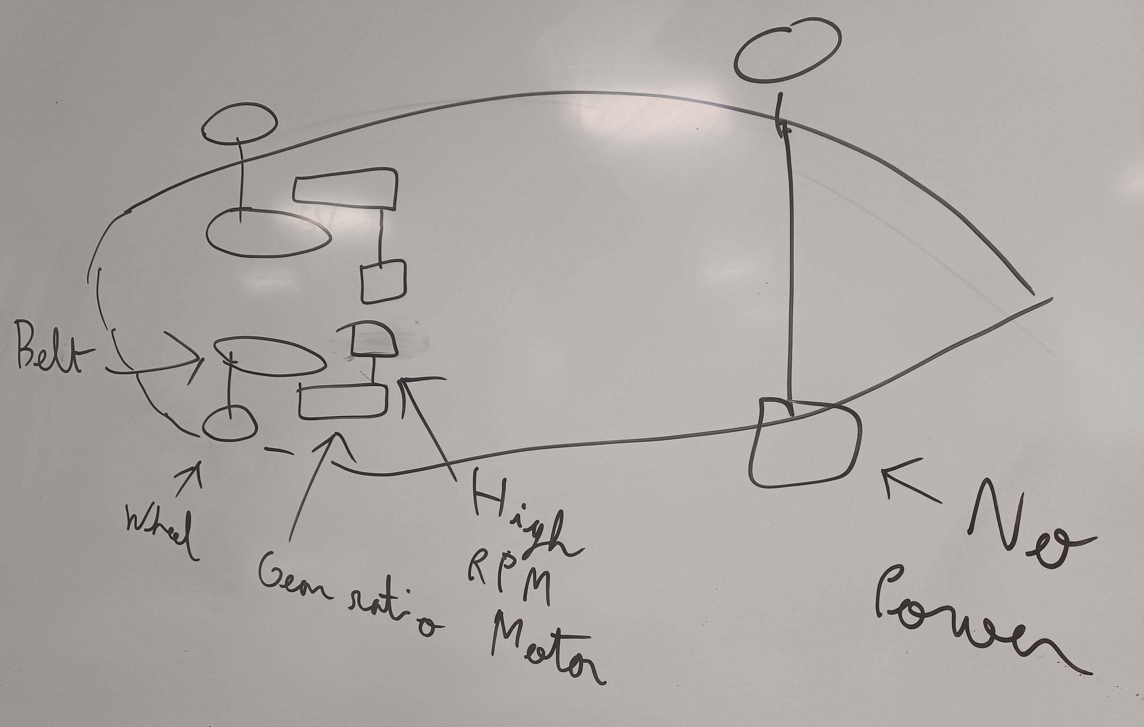
Made a 3D model of the connexion between the wheel and the drive shaft.
Made the model for the main body of the hanger (rough), how the motor is supposed to connect the main structure and transfer the mecanical movement to the wheel. Gear ratio is currently no-existent since caculation showed it probably wasn't needed. 1900 RPM on a 60cm ball is 5m/s, around 18mk/h or 49.2125 hand per second. Assuming 50 to 100% efficiency, the final speed is appropriate to be dangerous wihout causing legal trouble.
Made the minimum electrical circuit to power two brushless motor with a lipo battery with control it with a radio receiver. A secondary batery will power the arduino via a driver. While this could be used to guide the skateboard, the receiver main use will be to turn on and off the dangerous skate. Later version will include the selected sensors to allow the chaotic silicion brain of the skate to be dangerous.
Created the hackaday file
Listed all component and added "have", "don't have and need to order" category to each of them.
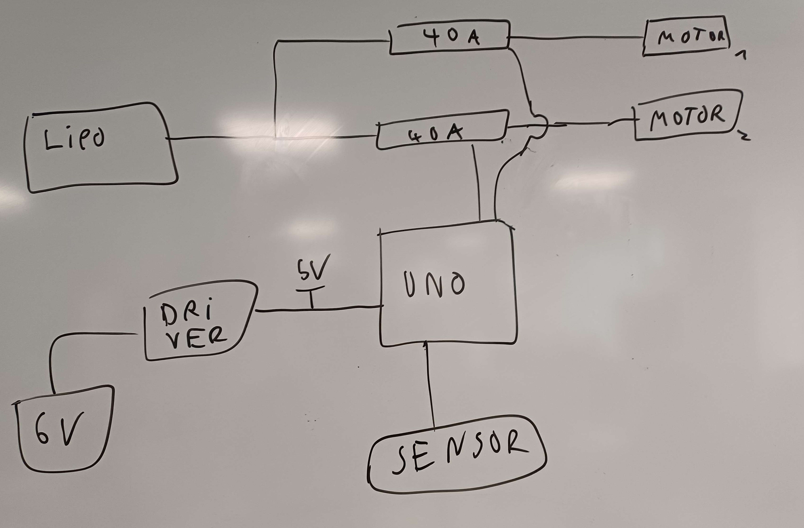
Draw the basic schematic for the wiring and skateboard structure.
Added rudimentary instruction as to how to build the skateboard.
Structure drawing :
Wiring drawing :
13/03/2024
We defined project goal
Found a 3D model similar to our need for the hanger and the gear ratio.
Defined the structure of the project (Individual motor and gear system for the direction) front unpowered and fixed wheels.
20/03/2024
We created a one note containing all the research in an organized way with different links for each part of a regular skateboard. it includes all the different types of variables that a board could have from the wheel to the technical part like the remote control. It also has technical data and tutorials.
https://esmefr-my.sharepoint.com/:o:/r/personal/loris_le-roy_esme_fr/_layouts/15/Doc.aspx?sourcedoc=%7B70916AA8-734F-4E57-82C3-2169487C08AB%7D&file=Loris%20%40%20ESME&action=edit&mobileredirect=true&wdorigin=Sharepoint&RootFolder=%2Fpersonal%2Floris_le-roy_esme_fr%2FDocuments%2FLoris%20%40%20ESME&d=w70916aa8734f4e5782c32169487c08ab&csf=1&web=1&e=cfE6oN&cid=7b6252d9-3ada-4d58-96d4-e0ba3a71f80a
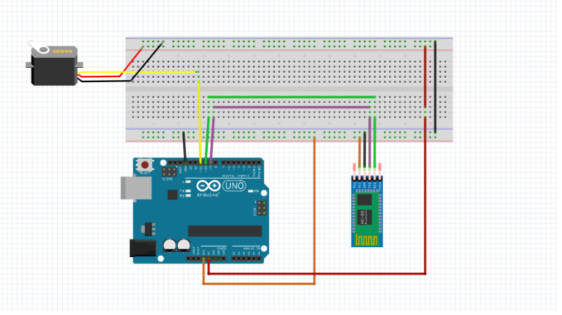
We then made an arduino basic circuit containing a bluetooth reveicer and a servo motor.


 Up-up view

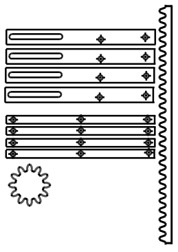 The mechanism is a combination of the these, with the first one creating the horizontal movement necessary for the second one to work and lift the structure.


 Hacker404
 Jamie
Jamie
 Quinn
Quinn
 charliex