 Bharbour
This project started out from my looking at tomcircuit's #TI-57 Programmable Calculator Hardware Retrofit project. That project is driving a 12 digit (or so) 7 segment LED display via CPU scanning. Thinking about how it could be done without so much CPU overhead drifted into thinking about using one of the IS31FL3730 LED Matrix driver chips in a slightly off label way. In the end, this approach would not help tomcircuit's project because he is also using the scan signals to scan the keypad. The scanning done by the IS31FL3730 chip is pretty much asynchronous to anything, so it would be more work than it would be worth to try to use it in an application like that. Also, I had to play some games with the LED selection to get 16 digits from this chip.
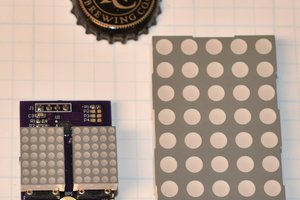
IS31FL3730 chips will drive 2 8x8 LED matrix displays per chip. One matrix needs to be common cathode and the other needs to be common anode since the chip shares the row and column drive pins between both displays. I found some little Wurth displays that were available in both common cathode and common anode. On this board, there are 8 common cathode displays and 8 common annode displays. The displays are small enough that the PCB is not expensive. Cheap is good on this project since it does not have an intended use at this time.
What I had envisioned on this project was that control of the segments for each digit would be in one of the 8 bit column matrix registers. A simple lookup table in the driver would map 0 to F values on input data to proper characters with 7 bits for the digit segments and 1 bit for the decimal point. When I designed the PCB for playing with this, I swapped the rows and columns, which makes the driver software become a lot less simple.
The basic idea is still good though because the driver chips are pretty inexpensive at about $1 in lots of 10 chips. Half a dozen ceramic caps and 3 resistors don't add much to the cost. The Wurth displays (157119S12701 and 157119S12801) are $0.77 each in lots of 10. The PCBs are about $10 each from OSH Park.
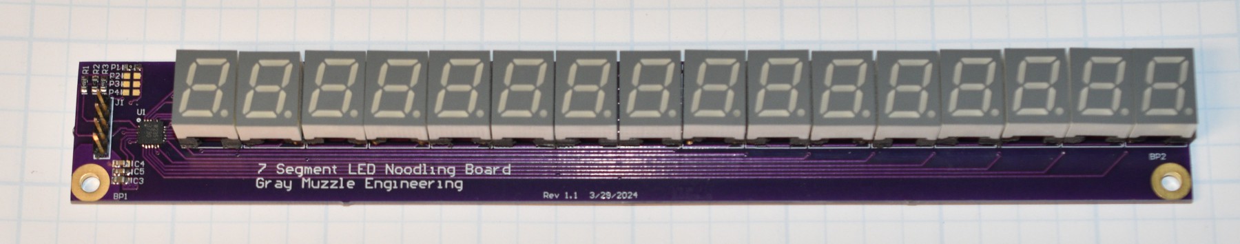
When I went looking for 10 pin DIP sockets for the displays, they are scarce and expensive. I used 14 pin DIP sockets that are cheap and readily available and cut the bottom 4 pins off. There is enough space on the sockets to get a hobby razor saw between two pins to cut the socket easily.
I'm not sure what I was thinking about when I did the hardware design for the board. In my previous hardware designs that drive matrix LEDs, matrix 1 gets connected with the cathodes on the column signals and matrix 2 gets the anodes connected on the columns. In that configuration, matrix 2 uses a different character generator table from matrix 1 to rotate the characters to match the wiring. On the 7 segment board, all of the display segments got assigned on the column signals which means that segments for each digit are scattered across 8 column registers (yuck). Inside the chip, there are two sets of column registers, one for each matrix. On this board, each matrix drives 8 displays.
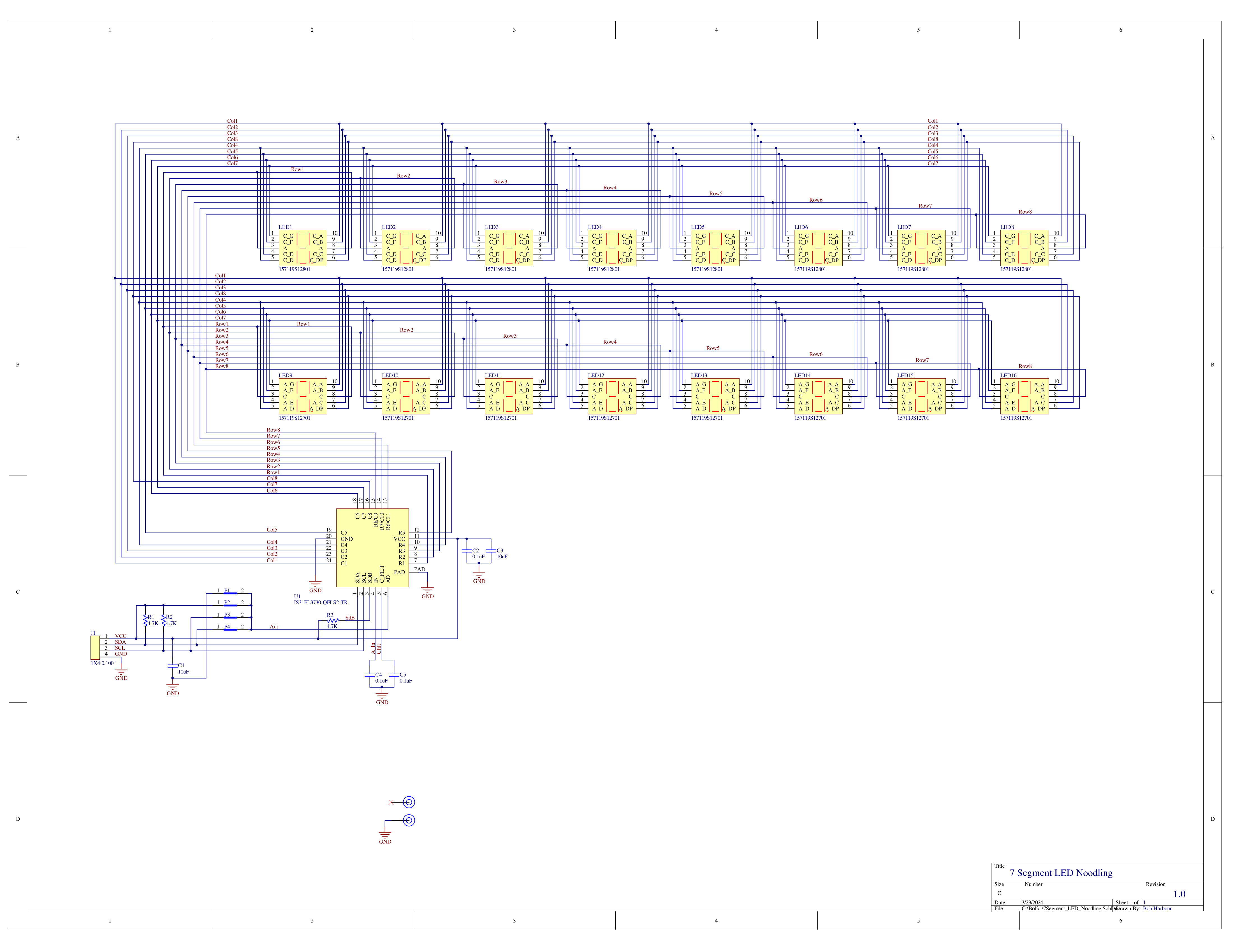
Also, I got the LED physical locations on the schematic placed poorly to help make sense of stuff. The schematic needs to be re-drawn and the board layout corrected.
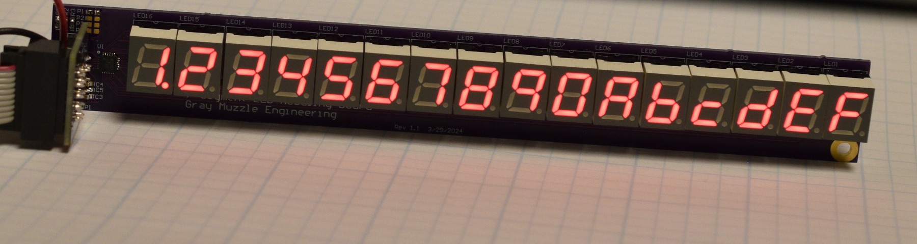
The board works and the driver software works. In spite of the warts, it demonstrates that the idea is good.


 Stephen Holdaway
 zakqwy
I like the innovative way you used this driver IC to get 16 digits! I can imagine it’s more than just a bit complex with the swapped rows and columns. You’re correct that I considered trying to use a driver IC such as this for my TI-57 project, but abandoned the idea for several reasons, one being exactly the reason you stated; no (known) way to synchronize with display scanning to read the keyboard as well. Thanks for the mention!