 board707
Flip-dot digital block looks like this:
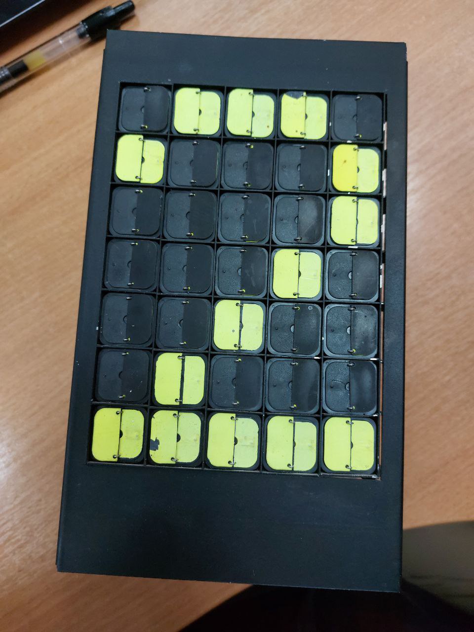
The blocks has a size about 200x120mm and weight 1.7 kg
Idea of the circuit
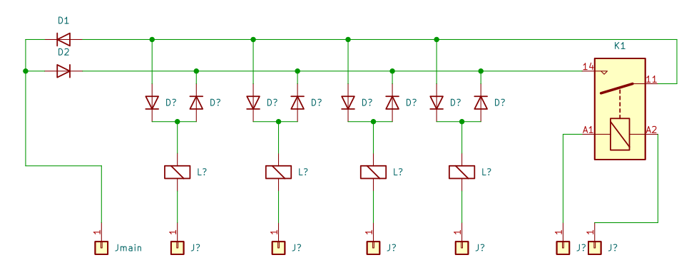
The image is formed by blinker dots.. Each blinker is a plastic curtain controlled by an electromagnetic coil. One side of the curtain is black, the other is painted with reflective paint. When voltage is applied to the coil, the curtain opens or closes, depending on the polarity. After the tension is removed, the curtain maintains its position for months and even years. Each module has 35 blinkers, forming a 5x7 pixel image. The blinker switching diagram is shown below (for simplicity, there are only 4 coils out of 35 in the figure).
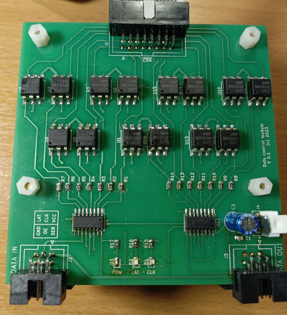
In order not to develop a complex bridge circuit for each coil to change the polarity, we decided to use alternating current. The idea of control is shown on the diagram below. By turning on the desired blinker, we switch optotriacs U3-U6, and the polarity of the signal is selected by one of the opto-relays U1-U2, connected through diodes D3-D4. All that remains is to apply alternating current to the block for one period and a half-wave of the required polarity will switch the selected blinkers:
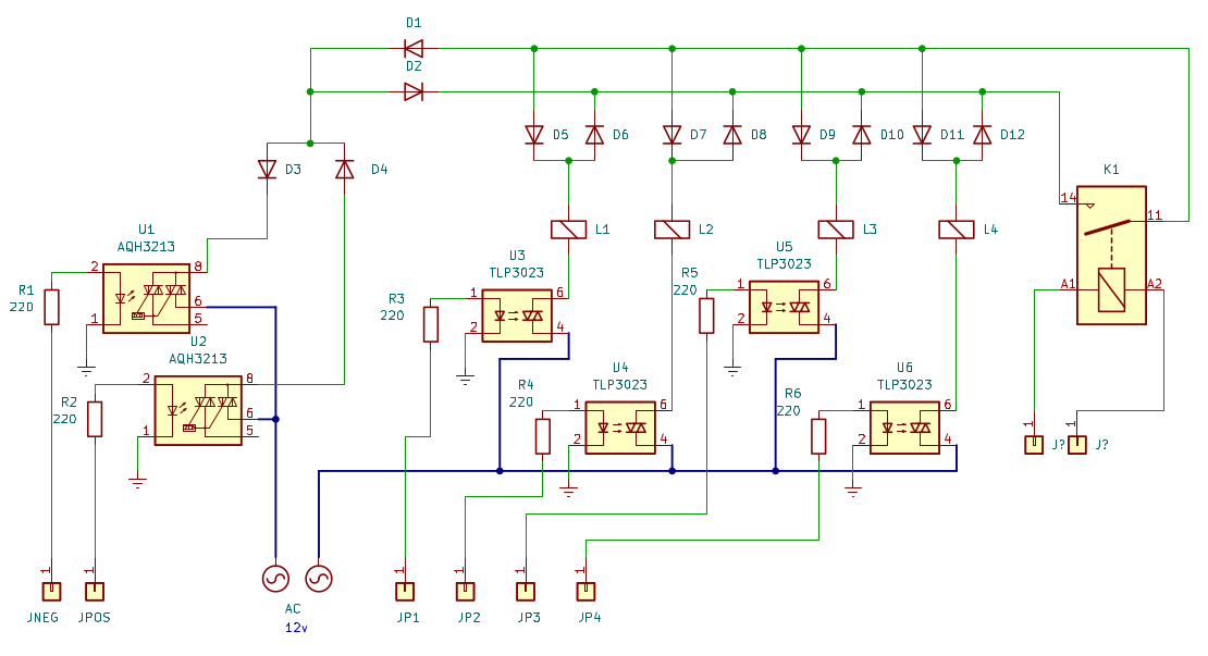
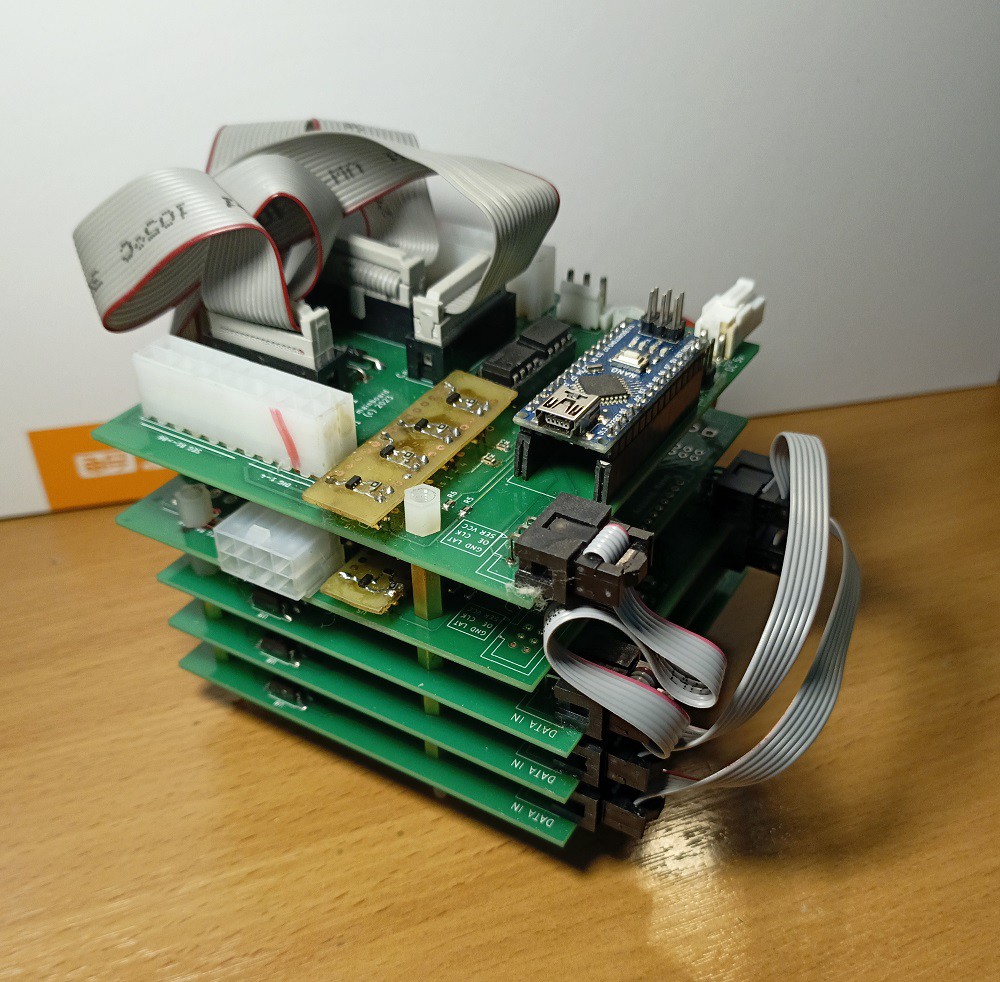
The circuit turns out to be quite large - 35 optotriacs - but at the same time simple and cheap. The triacs are controlled through a cascade of five shift registers - one for each vertical column of blinkers. The project uses 6 flip-dot digits - 4 for displaying the clock and two for the date, as was in the original. The selection of the desired digit for updating is carried out by relay K1 on each digit, switched by mosfets. The main controller of the project is Arduino Nano board.
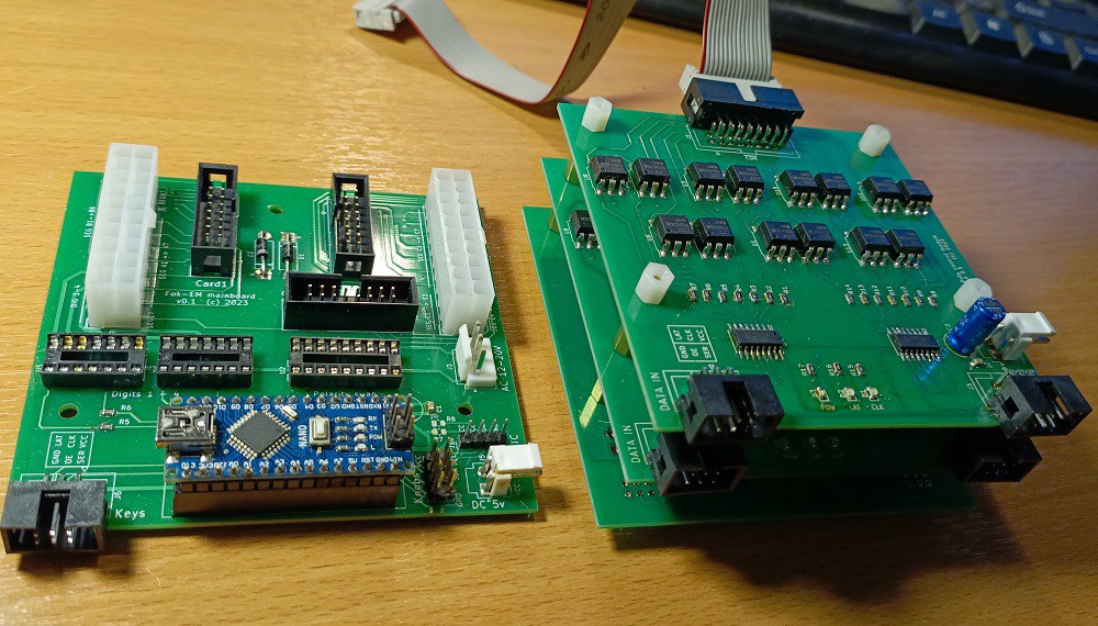
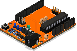
PCB
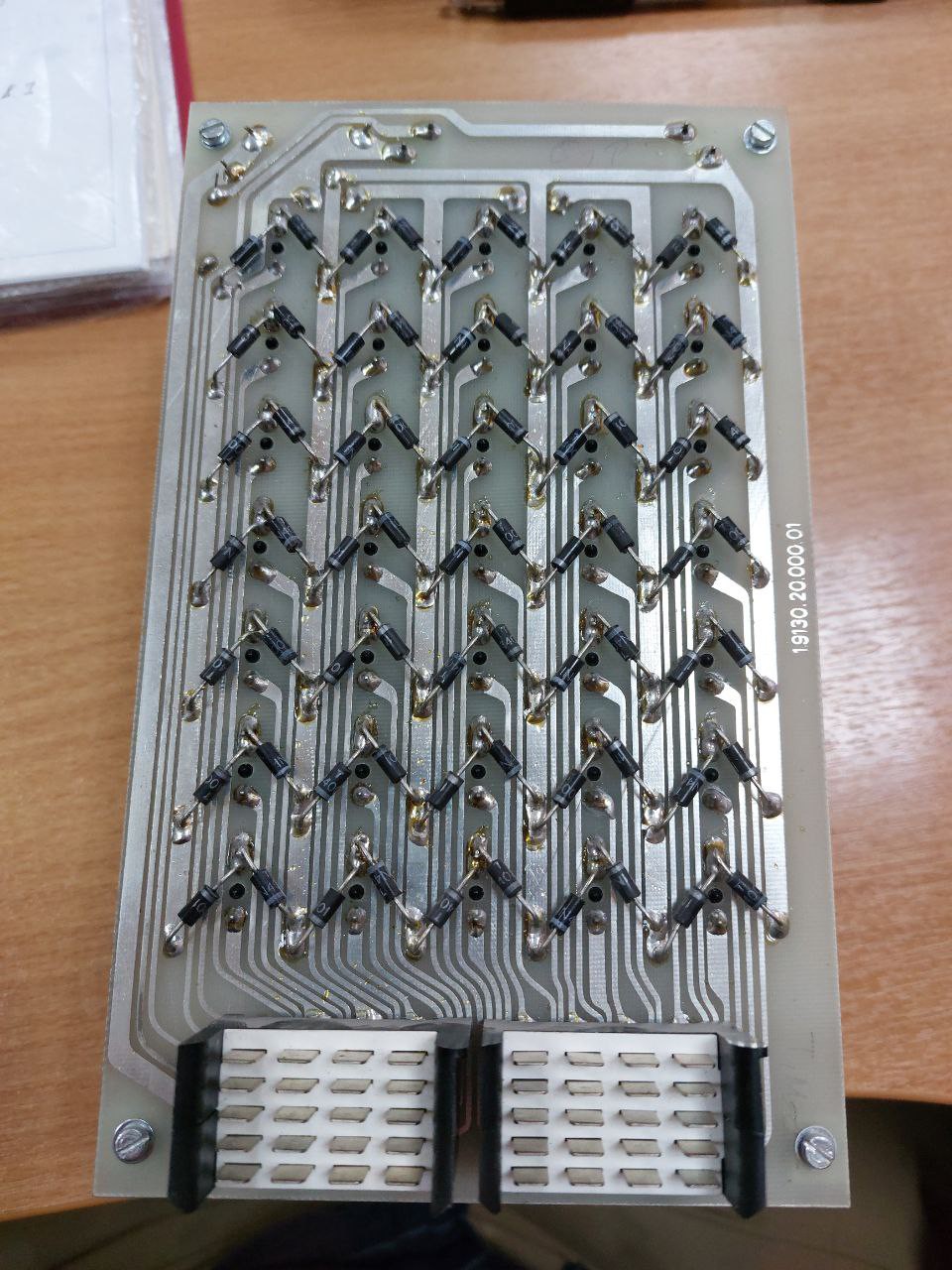
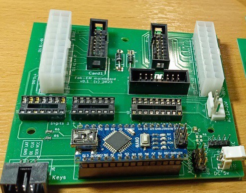
We have developed two types of PCB (drawn in Kikad and manufactured by PcbWave). The right board is for triacs and shift registers (14 and 2, respectively). We need three such boards. The left board is a control board for Arduino, polarity relays and connectors.
The code
The project controlled by Arduino Nano board. The code can be dowloaded from project's Github page: https://github.com/board707/Fok_Gyem_flipdot_clock/tree/main/src
The code use Arduino library for the DS3231 real-time clock (RTC) by Andrew Wickert.
Sample videos
 Silícios Lab
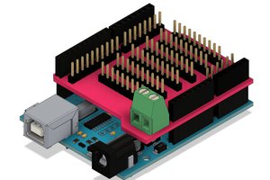

 Kris Slyka