 Frédéric Druppel
LET'S DO THIS!
Progression : it rolls !!
Project logs :
When a tricycle meets a lawnmower engine and two crazy chaps
Already have an account? Log in.
To make the experience fit your profile, pick a username and tell us what interests you.
LET'S DO THIS!
Progression : it rolls !!
Project logs :
Because we wanted this project to be relatively cheap, we used an old office desk to make our frame. This didn't cost us a single penny ^^
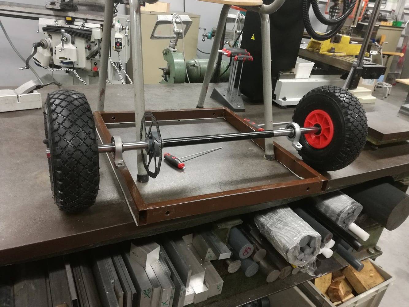
About the axle; we used an old steel tubing that we turned to the right dimensions so we could put the wheels and bearings on it. As you can see in the picture above, it fits !! At this point we've already made the mounting bracket for the disk brake disk (made from PVC stock).
•
Now that the axle is done, we can start working on the power transmission. We haven't added the motor and pinion gears yet, but we'll leave a link *here* for the future project log about that specific topic.
We decided to use only one driven wheel as the tricycle was kinda wide, and we didn't really want to use a differential transmission system.
Because the rear wheels we're using have an embedded bearing we have to make a sort of bracket to drive the wheel from the axle. The wheels themselves have a sort of "eight-armed-star-shape" casted in the plastic (as you can see in the first picture), probably for strength as these wheels are made for trolleys; so we had to engineer a part to accommodate for that. The picture below shows the milling of the notches in the PVC part.
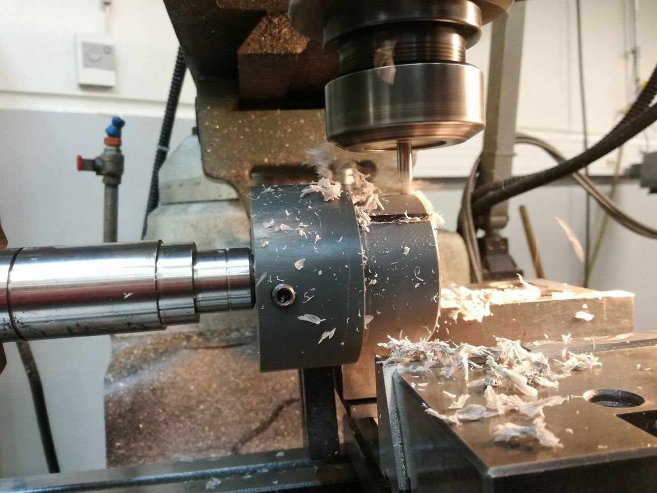
The principle is simple. The notches in the milled part fit inside and around the wheel's inner "arms", while the part itself is fixed on the transmission axle. It may be overkill, but hey, we had access to the tools for that, so why not use them ? :p
Speaking about overkill, to get a nearly-perfect alignment of the notches, we used a manual "fourth axis" dividing plate, just because we could :D
•
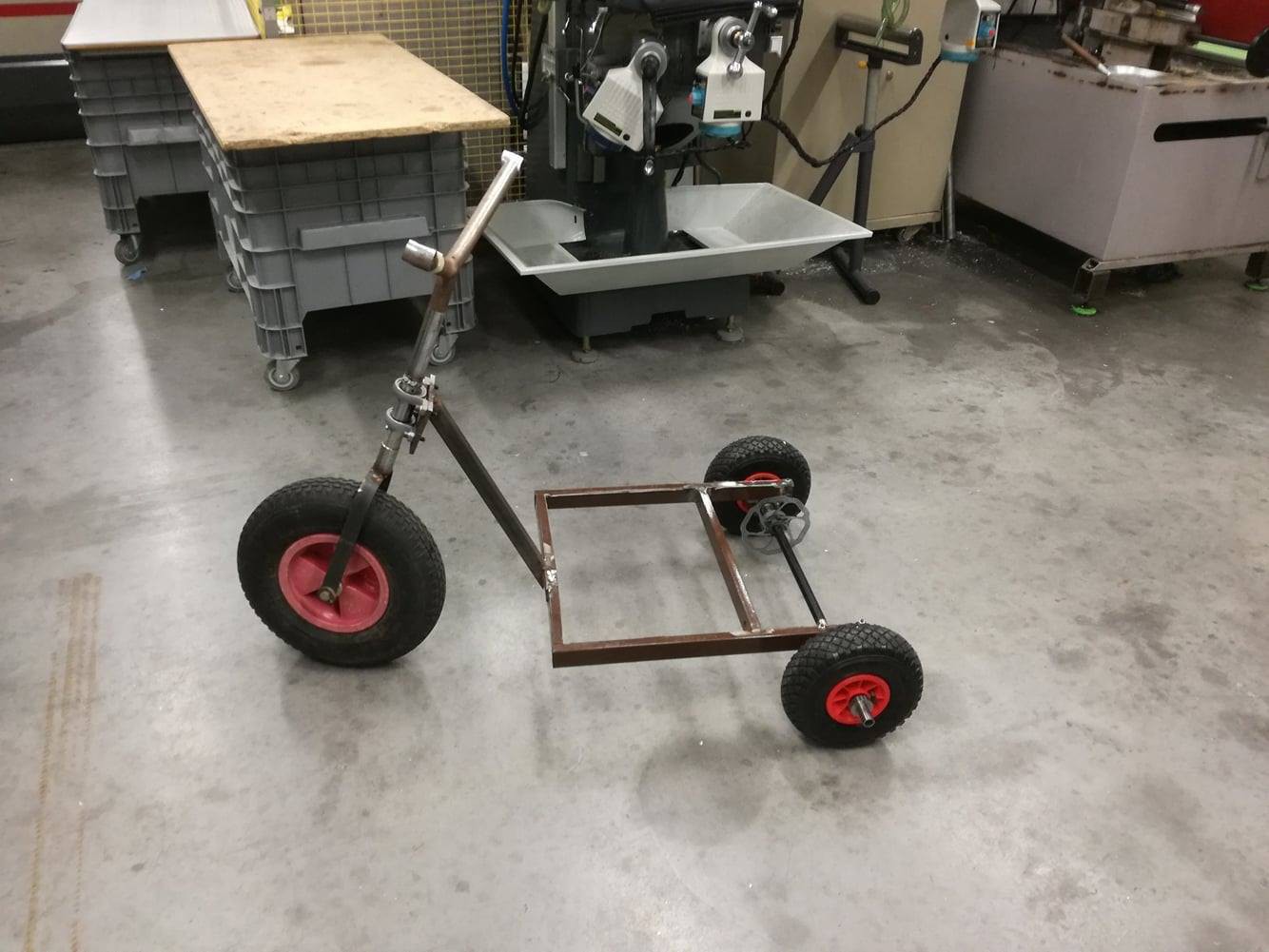
The piece of table we used was originally square, and one side was interfering with the main axle and axle parts (mainly the disk brake). To solve this problem we chopped one side of the square frame and moved the chopped piece to the front a little, so we could put the axle where we wanted and still keep the rigidity.
Here's a picture of the finished frame with everything we've made so far attached :
•
Now you may be wondering about the stiffness of rectangular metal tubing, and to be honest, we are too :3 After standing on the partly finished frame, we determined that the stiffness was nice and got the "Good enough" seal of approval.
        .---.         ________________
       /o   o\       | Good enough !! |
    __(=  "  =)__   <_________________|
     //\'-=-'/\\
        )   (_
       /      `"=-._
      /       \     ``"=.
     /  /   \  \         `=..--.
 ___/  /     \  \___      _,  , `\
`-----' `""""`'-----``"""`  \  \_/
                             `-`
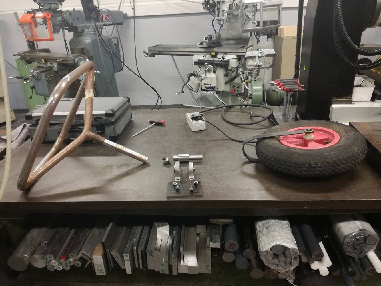
Remember that wheelbarrow wheel I had laying around? Well, the tyre was flat, and I was too lazy to fix it. However, I found another good one in a junk pile in my old college, plus an old steel coat hanger support, which will come in handy for the handlebar.
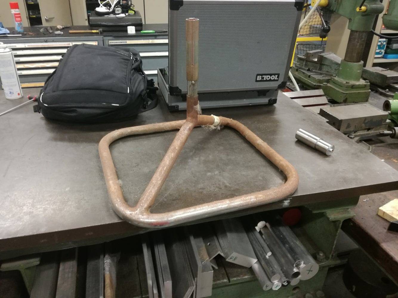
We machined a steering support held by two pillow blocks (20 and 25mm in diameter, I had those laying around), bolted into a 1/4in steel plate.
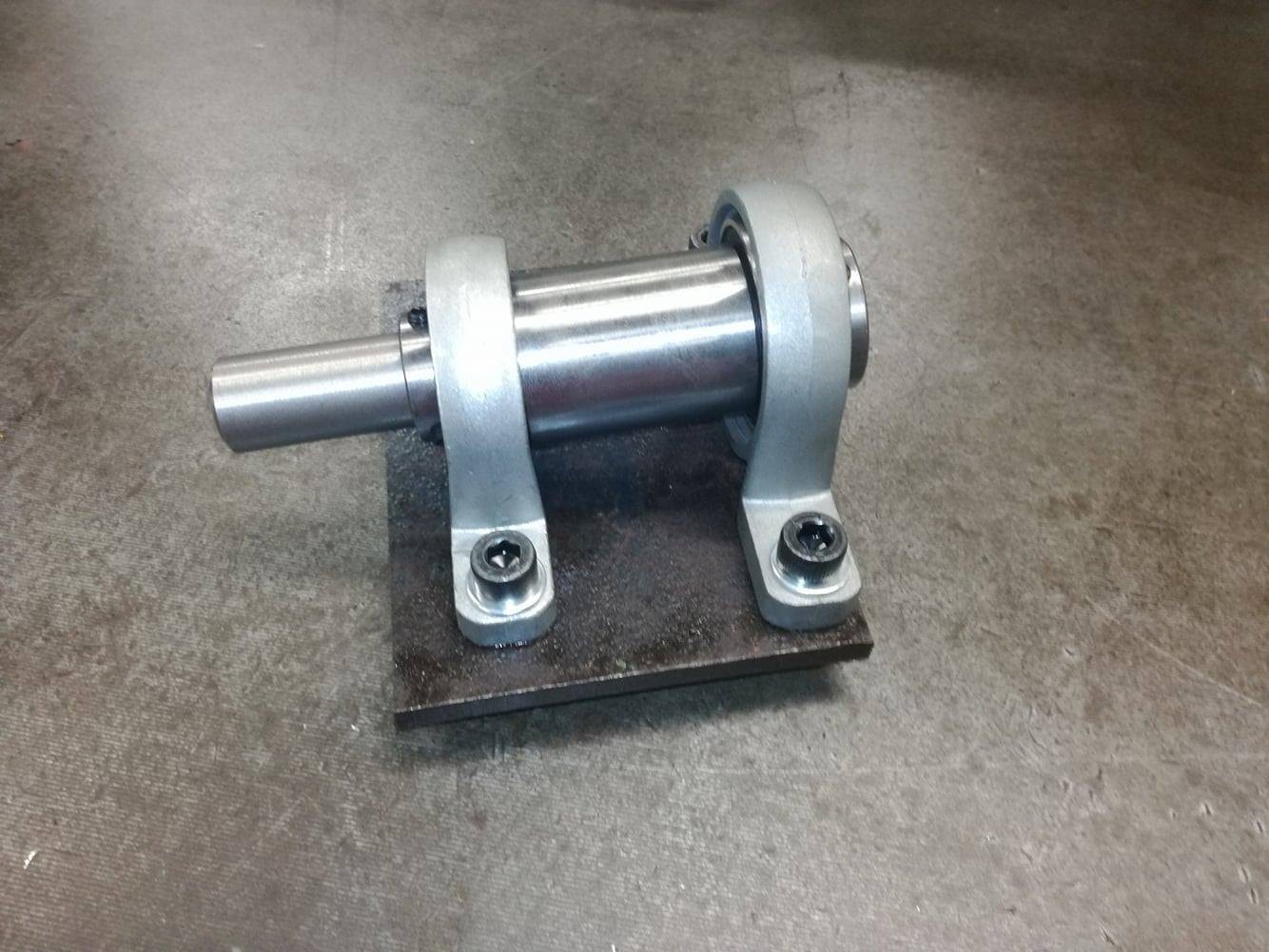
The handlebar will be bolted on the thickest part (through a piece of
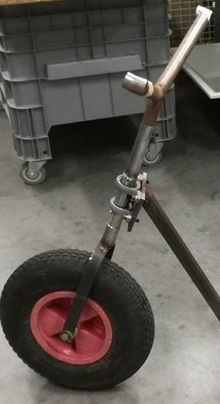
pipe that fits over the coat hanger support) of this rotating axle, the lower, thinner part will be connected to the wheel. The wheelbarrow wheel is held by a hand-bent flat piece of steel, welded on another steel cylinder we machined to fit this lower part.
 The steel plate is then welded onto a square tube and onto the frame itself.
An old table frame was also recovered in the process, along with a classroom chair, @Frédéric Druppel will mention it in the next log :)
Now that we have our design almost set, let's look for the other parts:
That's all for now!
Probably a square rear end, front will converge into a single point to hold the fork for the single front wheel.
To be continued.
After a late, long chat with Manoel about which wheels we where going to use, we found some interesting links to where we could buy some.
Here they are (I also posted them for us in case we forget them) :
1st idea https://www.befr.ebay.be/itm/300919651560
2nd idea https://www.befr.ebay.be/itm/370376940748
4th idea https://www.amazon.fr/dp/B01N5HPB9P/ref=cm_sw_r_cp_api_ztTdzb2RNPE28
The 4th one is probably the one we'll end up using, as it's cheap and, well because it's cheap.
For the sprockets, we'll firs search in a scrapyard or something, but of we don't find anything, we'll probably buy some of those : http://www.befr.ebay.be/itm/35-Chain-Sprocket-9-10-11-12-13-14-15-16T-Pitch-9-525mm-For-3-8-35-06B-Chain-/152473406789?var=&hash=item23801f8d45:m:mYVo2KnvnOnbpvRAAwq5r4Q
The shaft diameter will most probably be 20mm
That's all folks !
If we feel like complicating things, we may look at a relatively simple yet really effective system : the double-cone clutch.
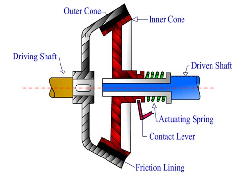
It's a bit more effective than a belt-tensioning system, but harder to make, but it's a kind of challenge ^^
there's a nice website to calculate the optimum dimensions and stuff for the needed application (well kind of) (link)
We'll see ¯\_(ツ)_/¯
image courtesy of here
Two wheels, one free, the other one connected to the engine.
Clutch can either be integrated on the engine (if using chainsaw engine), or a simple belt tensioning system.
Things are getting a tad clearer.
The wheels should be decided by now, and will use a 20mm shaft. This helps a lot designing the driveshaft itself. Now, we can't drive both rear wheels, as it'll be a problem whenever we'll take a turn. Instead, only one wheel will be coupled to the driveshaft (through a custom coupler), the other one will just sit on its bearings and spin freely.
The entire shaft should be held through two bearings on pillow blocks, pretty easy to bolt onto the frame.
We'll probably end up using a Husqvarna 165RX engine, 65cm³, about 3HP. Pretty light for that power. We'll have to adapt something on the output shaft.
The engine's backplate looks like this:
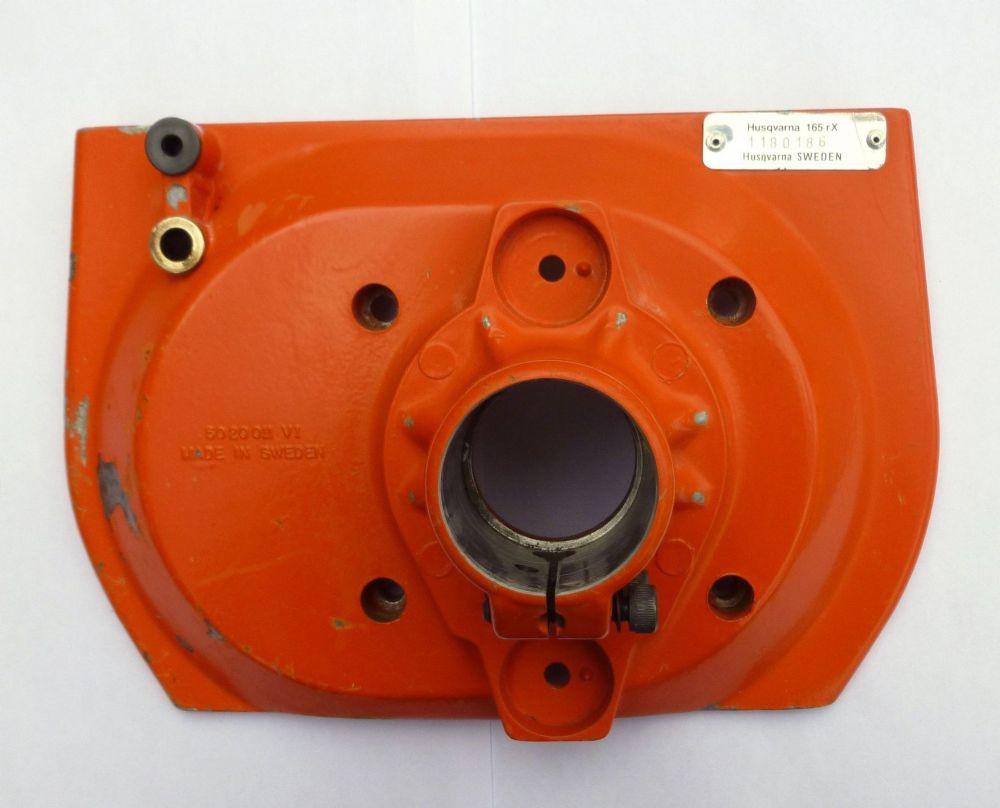
I'll probably find some tubing that adapts on this coupling. It'll be directly welded on a square pipe. The output shaft (press-fit onto the clutch bell) will go through it, and will be held by a couple of bearings with pillow blocks.
Second choice would be a Stihl 25cc engine: less poweful, but with the right gear ratio, we might have enough torque to push it up to 10km/h...
The power from the engine shaft is transmitted to the wheels through a sprocket. Probably something like this.
The sprocket's size on the drive shaft has yet to be determined, but apparently a 5:1 ratio seems sound (according to this source). A custom coupler will have to be turned on the mill to match the 20mm driveshaft.
We'll try to use a T8F chain, widespread standard (and it's metric!). That or a #35 chain, seens to be pretty cheap too. @Frédéric Druppel also has a #40 sprocket, we'll have to choose between those three possibilities.
Another "urgent" (ahah) matter. eBay provides lots of cheap disc brakes and calipers for bikes, for around 10€... Another small coupler will have to be turned to mount it onto the driveshaft.
As for now, the priority is set on the rear shaft itself: the wheels, the axis, the bearings and the braking system.
Good thing with a tricycle: steering is easy. Bad thing: it's unstable.
Was thinking a simple bike wheel on an axis.
More to come
Build at your own risk !! We know you're smart enough, so we suggest you to just look at the pictures & drawings, and make your own version of it :D

Legal ? Well if the finished monster travels 2 meters or more, we may start to be worrying about homologation and stuff :3

Bearings? I can order some off eBay right away, they're dirt cheap and versatile :p
 Chris Low
 RC ORDNANCE
 matthewkleinmann
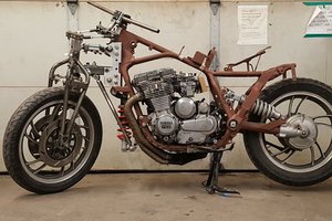
 sebwiers
Safe ? Meh, we'll take care of that at some point ^^