Pepijn de Vos
Music is of course an activity extremely suited for visually impaired folks, as it relies primarily on hearing. However, one major stumbling block is the tuning of your instrument.
For people without absolute hearing, there currently does not exists a good solution. There is an iPhone app that I've heard mixed things about, and some desktop software that is not suitable for tuning in many situations away from the PC.
Most experienced players that I talked to learned to tune by ear, because normal tuners use some LEDs or an LCD display for tuning feedback. But even they indicated interest in an easy to use portable tuner.
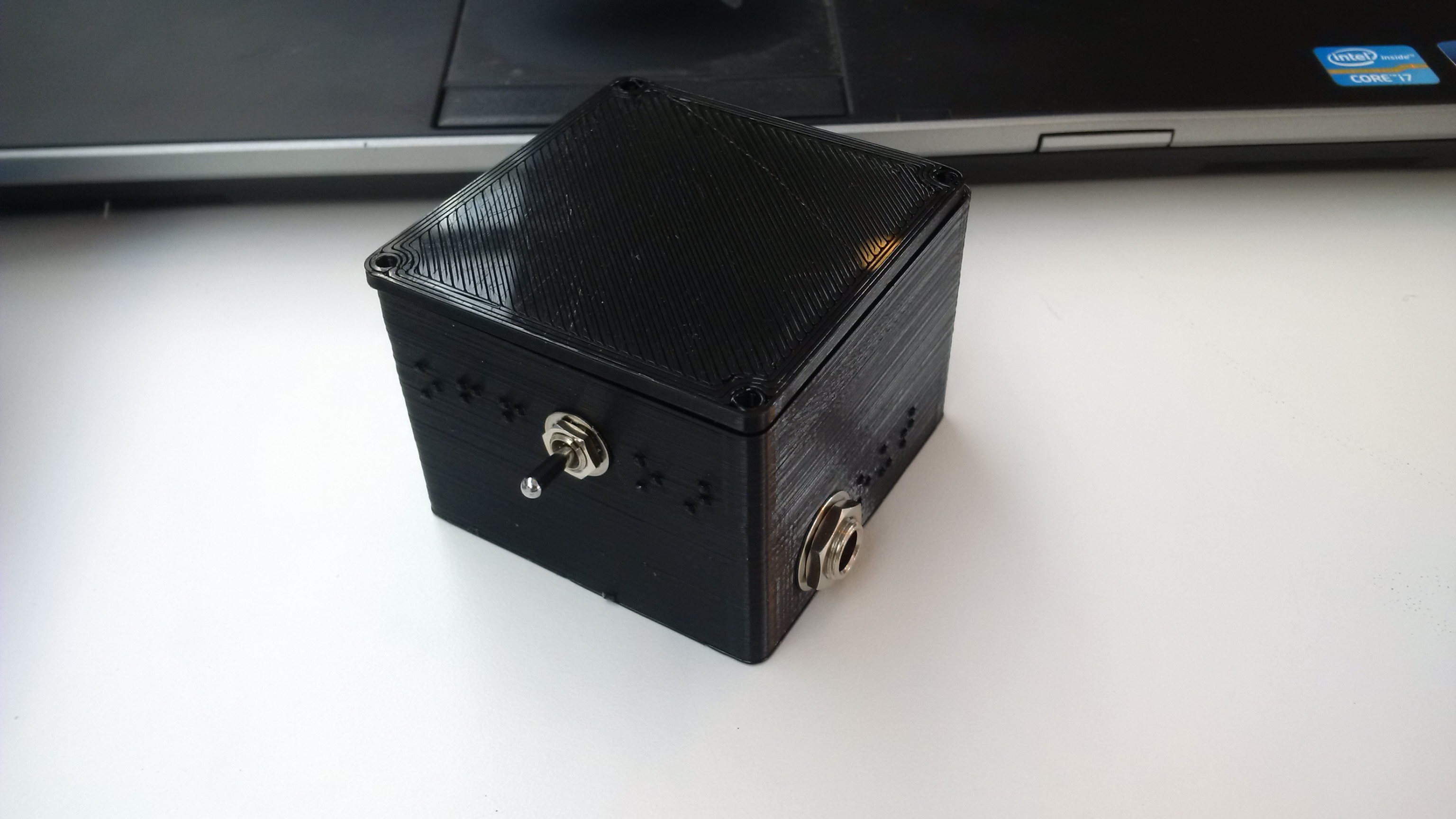
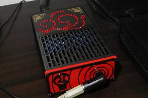
This tuner takes input from a clip microphone, and drives a headphone with an easy to distinguish clicking sound that indicates how closely in tune you are.
It takes its core functionality as an opportunity to innovate on the algorithmic side of things and I discarded the FFT frequency-domain based approach common to many guitar tuners. By modulating the input with a reference tone (much like your FM radio), the frequency difference between the input and reference can be extracted an synthesized into a clicking sound. This can be done in real time with very little CPU and memory.
The business plan for this project is very simple: Put it on Tindie and hope for the best. There are already people on the waiting list, so while I don't expect to get rich, I should sell at least a couple.
Hackaday Prize finals!
My tuner made it to the finals of the Hackaday Prize! Here is what that means and what I've been doing since then.
I won a thousand dollar, which I will put towards further development of this product. Part of it will be development costs (PCBs, components, and maybe a few new tools), part of it will be used for the first production run (starting small of course), and part of it will be put on Bounty Source to try to find contributors.
Bountysource
Over the summer holiday I worked on this project almost full-time, but now that university has started again, I have very little time to move the project forward. Since I made it to the finals, I spent all my time on debugging the current PCB revision.
So I'll be posting some bounties on the issue tracker to solve some problems for which I lack the time or experience to solve them quickly. Please get in touch if you think you can help so I can provide you with a PCB and anything within my power to get you started!
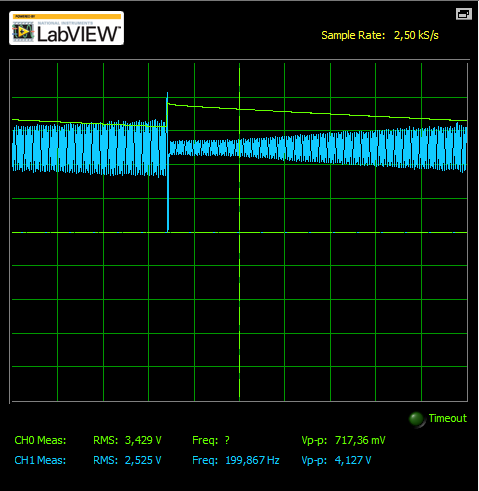
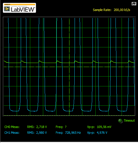 There are peaks of 100mV on the supply, compared to a 10mV input. No wonder... But why?!
 David Scholten
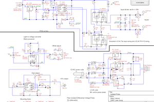
 michal777