Close
0%
0%

Arcus-3D-C1 - Cable 3D printer

3D printable, Open Source Hardware, tripod kinematics, cable driven 3D printer

Similar projects worth following
This project aims to be a very low cost portable 3D printer with a scalable build diameter and reasonable accuracy.

The design as rendered (OpenSCAD source) can scale from about 200mm to 600mm build diameter with the same parts just by using different length connecting rods. The build height is approximately equal to the build diameter.

The printer can also be 'flat packed' for transport by removing the vertical rods as just the system tension holds them firmly in place.

Hardware and software are working as designed now.
The current focus is on dialing in the tripod kinematics and homing settings, and then generating a methodology for others to use to do the same.

Origin

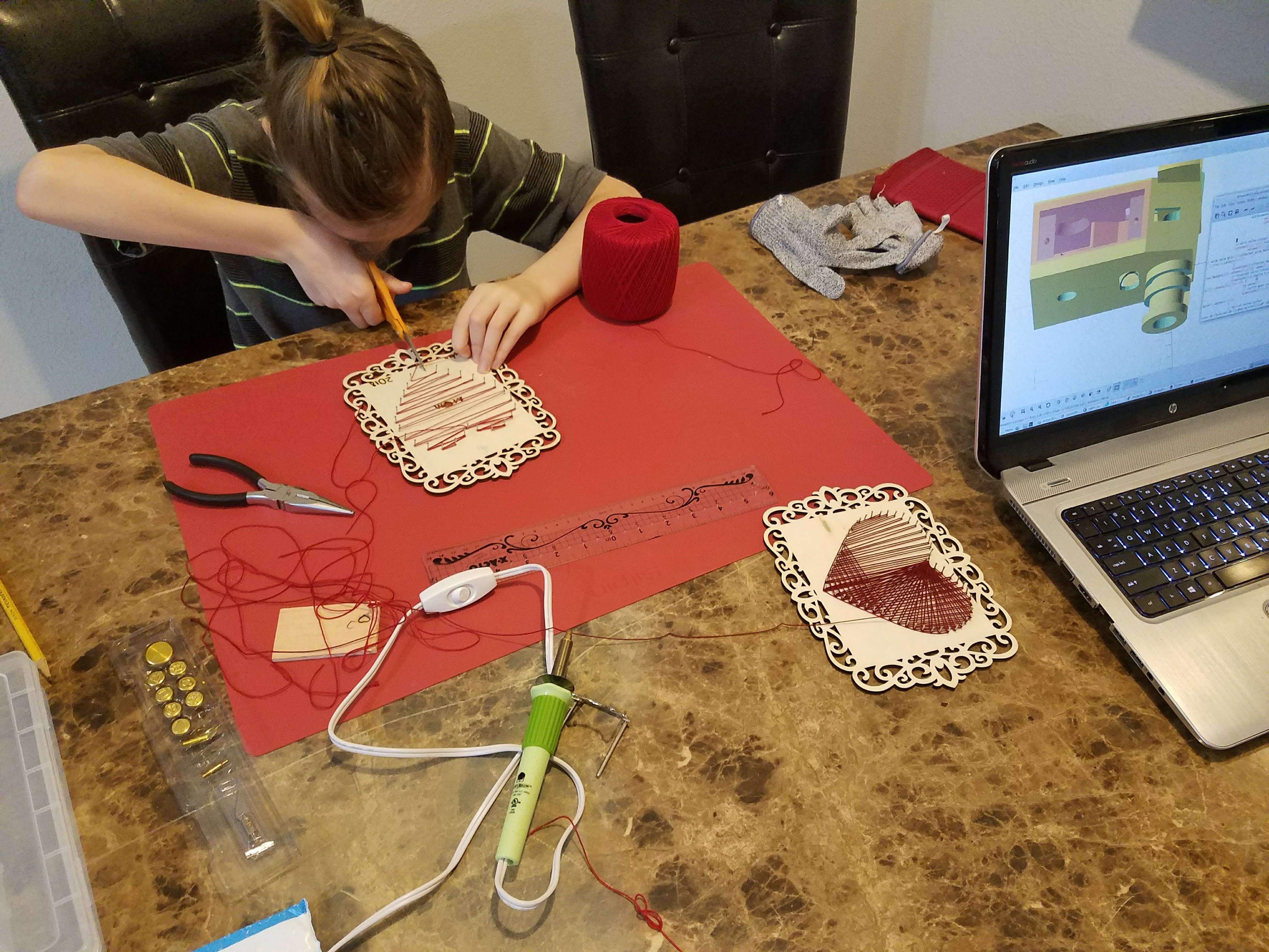
I wanted to make a simple, low cost 3D printer using the available parts I had leftover from other projects, so the C1 was born.  Designed it in my head, and then modeled the parts in OpenSCAD.  

All I didn't have on-hand was the rods (driveway markers and a garden stake) which cost me a total of $12.

 I started independently on this path, but then a forum post pointed me to the Flying Skydelta.   Awww...  It's a lot like that, with cheaper hardware.

System overview

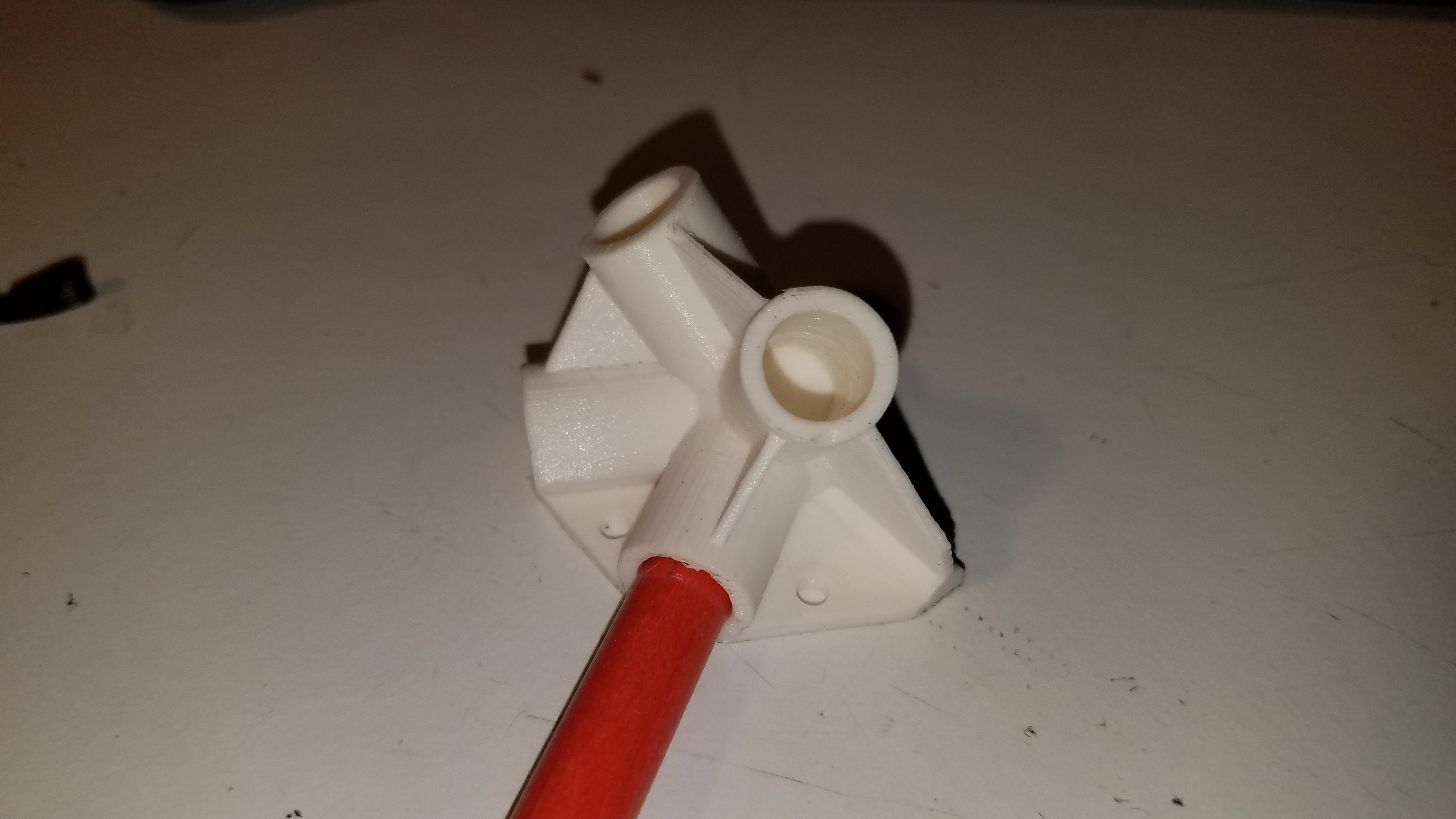
An octahedral equal length frame made from low cost fiberglass driveway markers support 3D printed corners.  The vertical components of the frame are held firmly in place by the line tension of the system, allowing them to be removed.  This facilitates flat packing of the printer for transport.

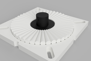
Each of the top corners house three pulleys sharing a shaft, through which cables are routed from the base mounted spool rod and steppers.  The relatively large distance from the pulleys to the spooling shaft results in a single layer of tightly wound cable.  This minimizes the error from the cable spooling up to less than 0.012mm allowing it to be ignored.

The outer two cables are wrapped in the same direction and serve to position the print head using tripod kinematics, while the center cable is wound in the opposite direction and is routed to apply tension to a central push-rod.  So as the outer cables wind up, the central cable unwinds to maintain tension.  The top of the push-rod is free to move, so as the end effector is moved right, the top of the push-rod will pivot and move left maintaining constant down-force throughout the build area.  The opposing forces on the spooling shaft also cancel each other out, resulting in the stepper motors only needing to support the weight of the end effector and not provide any actual tension on the lines.

The required cable length is not a constant however.  As the end effector is moved up, the required cable length of this system becomes shorter.  A compression spring mounted on the push-rod serves to make up this difference and maintain tension in all the lines.

Virtual pulleys

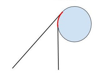
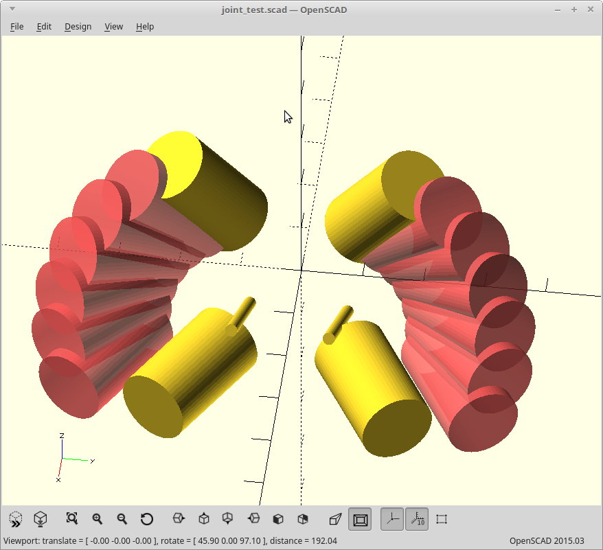
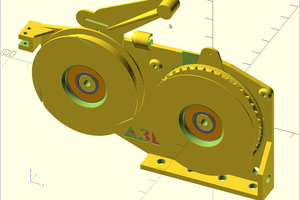
Tripod kinematics without any compensation assumes the end connections are points in space. They are not.  Pulleys can introduce significant error into the calculations: An 11mm diameter pulley can introduce up to 5mm of error into the resulting positioning.  This happens because as the angle to the pulley increases, the cable will wrap onto the pulley which will change the effective cable length and generate a horizontal and vertical offset. 


However...

If you use two pulleys with the cables wrapping in the same direction, this error effectively cancels out.  As you wrap up onto one pulley, you unwrap from the other pulley.

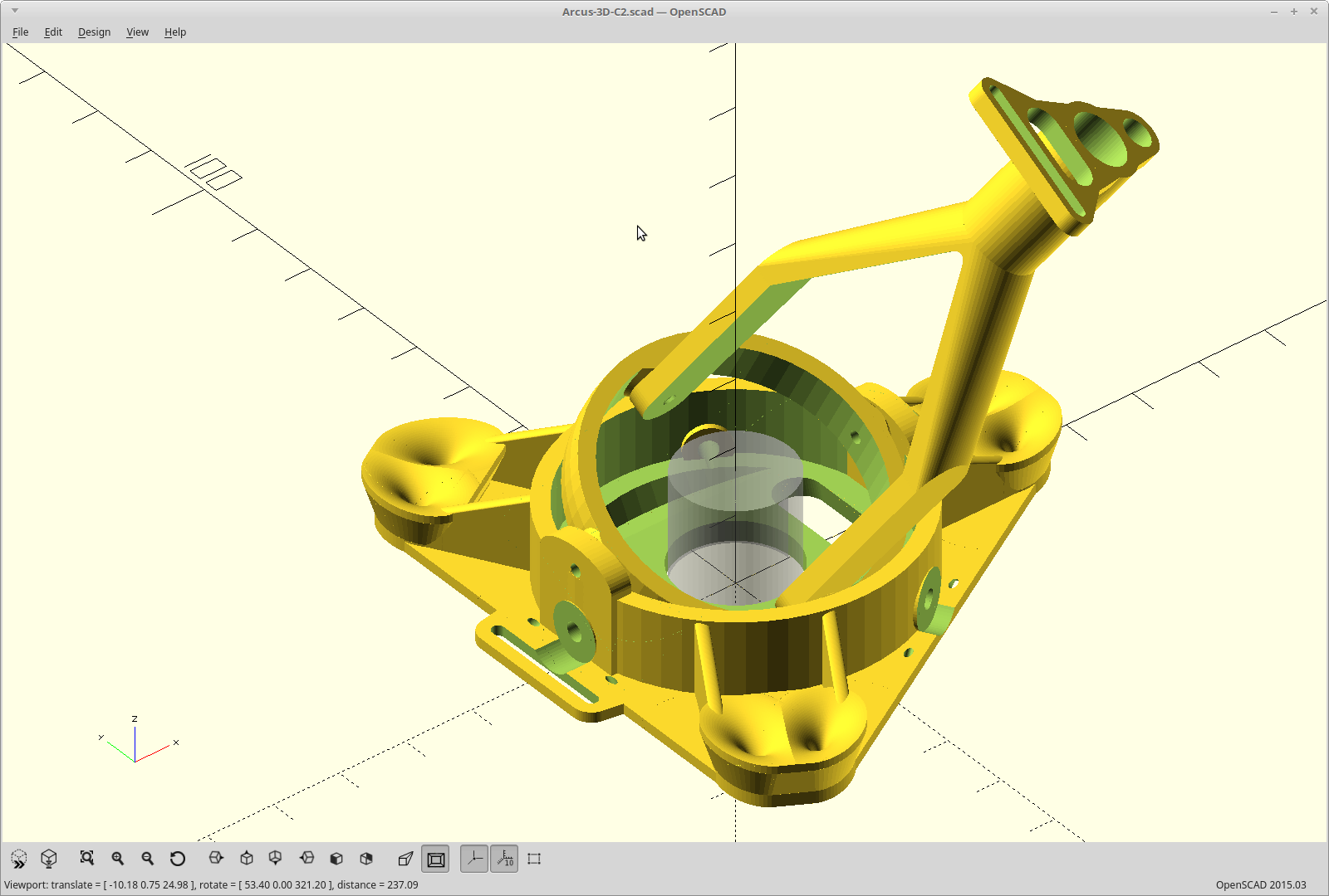
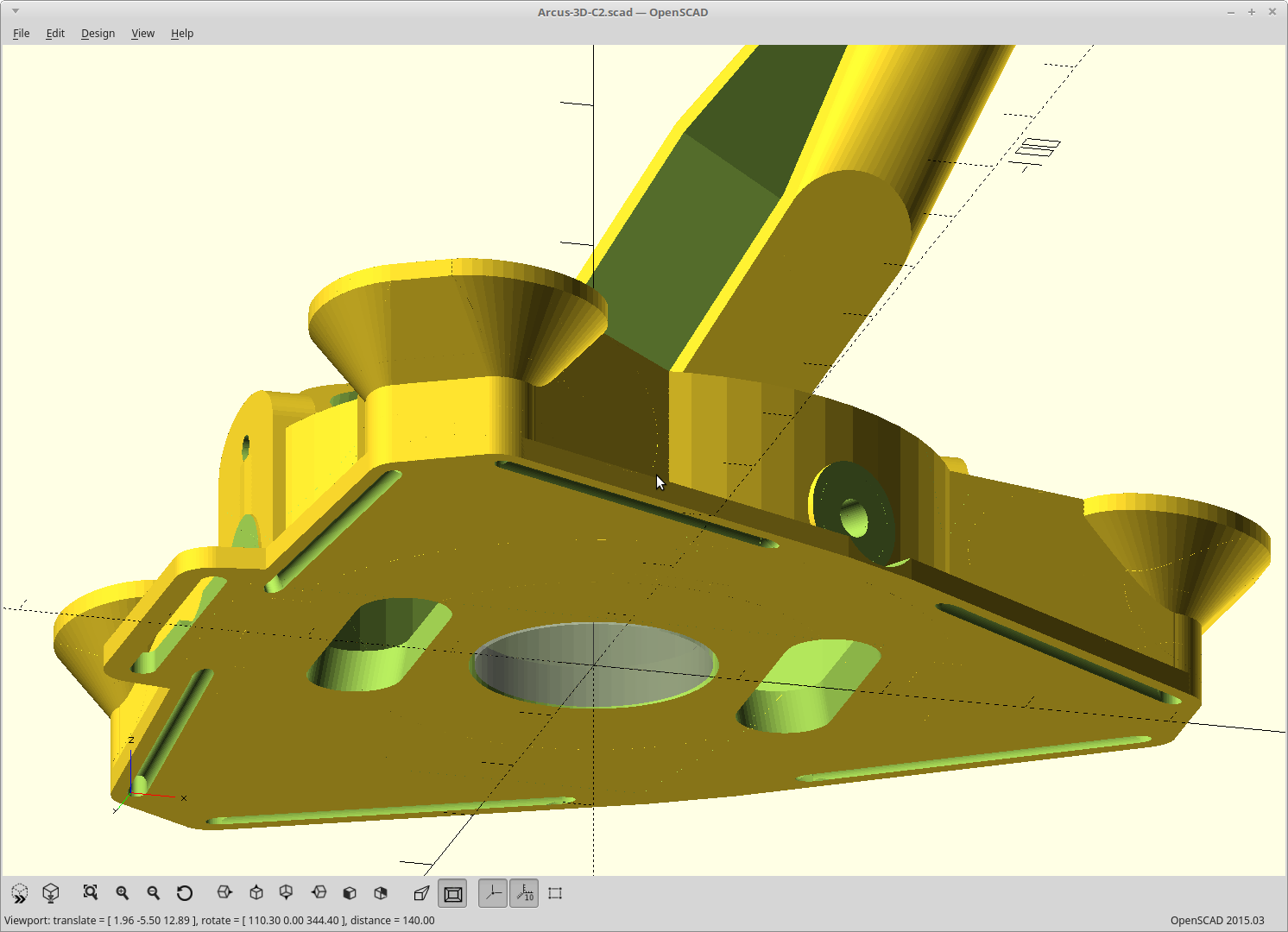
Rather than adding the cost and complexity of adding actual pulleys to the end effector, I have instead modeled the curve required to duplicate the effect of having pulleys into the top surface of the end effector, aka virtual pulleys.

There was one more issue with the kinematics as designed in that the upper pulleys do not rotate to face the end effector.  This has the effect of foreshortening the cable length when the end effector moves off axis.  This can be also be compensated for physically by altering the shape of the virtual pulley.

As the cable moving off axis from the upper pulley is causing a shortening of the effective cable length, an equal and opposite effect can be modeled into the shape of the virtual pulleys.  Essentially this compensation will result in some variation on elongating or warping the virtual pulley parallel to the axis of the actual pulley.  

I lack the expertise to properly model this system to determine the ideal virtual pulley shape, so I guessed.  It's a good guess though and gets me started.

End effector with virtual pulleys

So that means the existing tripod kinematics math can now be used as is with no...

Read more »

  • 3 × 2 pack 4ft fiberglass driveway markers $9
  • 1 × 4ft steel garden stake $2.80
  • 2 × logic level power mosfets $2
  • 1 × perf board and various caps/resistors $2
  • 1 × 12inx12in granite floor tile $8

View all 13 components

  • Squirt.

    Daren Schwenke09/22/2018 at 01:15 3 comments

    The bearing ID is 8.13mm.  The shaft OD is 7.89mm.  So I needed something to make up that difference.

    I went through all the rolls of tape I had around, and found one where exactly one wrap of tape, not overlapping, would make up the difference.  Worked, until now.

    The steppers running at the higher current get a little warm now, and I didn't hook up an enable pin on the drivers, so they are always on.

    Over the course of the last couple days, I've run them in and out a lot, and eventually an axis got 'rough'.  The adhesive had softened and the tape squirted out so the shaft was flopping around.  Another axis showed signs of failing soon...

    Tried in vain to make some heat shrink work.  It goes on, but it never compresses evenly and so the shaft is always wobbly.

    Then I tried AL foil.  Perfect.

    It takes about a 180mm long strip of foil, about 8 smooth and flat wraps, to make up the gap.  I end the wrap right where it started, so it's also perfectly centered.  I feel much better about 8 wraps versus the one I had before.

    There was a learning curve as to how to keep it from un-spiraling when you pull the bearing off though.

    Basically, leave some extra and peel from the middle out to the edge... and then compress it.  It mushrooms down onto the surface and keeps the whole coil in place.

    Pics later.  It's a tedious process taking about 5-10 minutes per bearing to do it right, but it's the only way I'm using these shafts without runout.

    <EDIT>

    The foil has worked well, with the exception of one where it also squirted out the end.  One drop of superglue fixed that.  I went back and did all the rest.

    </EDIT>

  • Weebles wobble

    Daren Schwenke09/21/2018 at 00:06 0 comments

    Noticed that at the edges of the build area, I was getting some offset from planar on the end effector, not related to the virtual pulleys.  The difference in tension between the near and far lines looked to be bending the top corner brackets.  On closer inspection, they weren't bending, but instead just wobbling where they slid onto the rods.  

    To allow them to be removable, I needed them to be a little looser than a press fit, or you end up breaking them when you take it back apart.

    So I've updated the top corners to add some more depth (18mm is now 24mm) to the pockets the support rods go into, and added the bit I've applied to other parts of adding flat spots to the inside of shaft pockets to allow for a tight, but slip fit over a greater range of error in either the rod diameter or the extrusion.

    The driveway markers I have vary in diameter over a range of about 0.2mm, which is a huge 2.5% variance given their nominal OD of 7.9mm. 

    Reprinted.  

    Adding the flats seems to have done the trick.

    Assembling using the updated parts now.

  • End effector updates

    Daren Schwenke09/14/2018 at 05:41 0 comments

    Modified the end effector, moving the leveling screws to the side and adding cable routes across the bottom so it can sit flat.  This should simplify leveling the end effector significantly.

    Previously the leveling screws were on the bottom.  Getting a screwdriver under there meant the end effector was up in the air, without a reference, while you locked the leveling in place.  This will be better.

    If all goes as planned, you should be able to loosen the screws, plop it down flat on the bed, and tighten them again and be perfectly level.

    For this version I also added a switch which enables/disables the fan mount and drops the ribbon cable guide for the Pi camera used on the P1 in its place.  I also added another optional guide to the pushrod joint to match and reshaped the existing guide to pass the 3 pin servo plugs through.

    <EDIT> Since this, I have also moved the virtual pulleys up to be on the same level as my pushrod gimbal.  Here you can see the new cable slots also.

    It's on the P1 now, and working like a charm.

    </EDIT>

  • Kinematics

    Daren Schwenke09/10/2018 at 17:39 0 comments

    I took the time to make my recent changes a proper pull request against Machinekit so people can eliminate this bit from the task of getting this up and running.  

    It fixes the problem of tripodkins not working properly at first if you are inverted (hanging) like this project.

  • Renewed Purpose.

    Daren Schwenke08/06/2018 at 07:40 0 comments

    I've decided to use this as my platform for driving the P1 and figured out how I can do it.

    Made some minor updates to the model to reduce the filament required and also to strengthen some areas that needed it.

    Updated parts are printing..  Fast.  

    Well, as fast as I can go with a single filament driving it anyway and still have good results... about 120mm/sec.

    Edit: One down, 5 more to go..

  • End Effector print

    Daren Schwenke03/14/2018 at 09:23 0 comments

    En-biggend the end effector wire slots in prep for passing a ribbon cable from the P1 and reprinted it.

    32x timelapse of the print.

  • Spin and fold.

    Daren Schwenke03/06/2018 at 04:31 6 comments

    Did a couple virtual experiments with how I could hinge the corners to enable 'spin folding'.  Rotate the top 60 degrees and it lowers to sit on the matching bottom.  

    Right now, you have to actually remove the 6 vertical members to fold it down.  This would allow you to just unhook and fold up 3 of the arms, and then turn/lower the top to meet the bottom with the remaining 3 arms still attached at both ends.

    Using ball joints this would be super easy, but that would also sacrifice a ton of rigidity.  Making the joints as pivots will work much better, but then the pivot axis vector and arm length/position has to be carefully planned.

     Here is the best I got so far.

    The large yellow cylinders are the current angles needed by the joints, and the pink ones are what you get when you rotate them about the axis represented by the smaller yellow cylinders.  The rotational axis vector was determined first and properly (as best as I can tell with just the math) represents the swing required of the arms during the 'spin fold'.

    Then I just iterated on offsets of the rotational axis until I got a path where the arm length matches reality.  

    I believe if I put a hard stop in the rotation in the extended position which is attached to the part of the triangle that stays static, I won't be giving up as much rigidity to do this either.

    The current iteration is still not good enough though, as that folded arm position intersects with where I currently have stepper mounts.

    It's a side goal, and the rest of the project can move on without it, but this would definitely be cooler.

    Fold yourself 12 times.

    EDIT: If anyone is ambitious enough to check my math, here is the 'so far' joint model in OpenSCAD.

    Only works for one of the two joints though, as the second joint (from the opposing arm) would actually occupy the same space as the first when folded... but that's just details.  :)  I could use a different set of offsets for that joint, and the ends don't acutally have to line up as they will be disconnected for that one.

    module joint_test() {
        wall_thickness=2;
        support_rod_dia=8.25; // Driveway marker diameter.
        support_rod_depth=20; // Depth of the pockets for support rods.
        roswell_constant=19.47;
        q=32;
        x=q/2;
        y=q/4;
        z=q/8; 
        translate([x,y,z]) rotate([0,45+roswell_constant/2,0]) {
            cylinder(r=1,h=30,center=true);
            for (i=[15,30,45,60,75,90]) rotate([0,-45-roswell_constant/2,-i]) translate([-x,-y,-z]) rotate([-30,roswell_constant,0]) translate([0,0,support_rod_depth*1.5]) #cylinder(r=support_rod_dia/2+wall_thickness,h=support_rod_depth,center=true);
        }
        translate([x,-y,z]) rotate([0,45+roswell_constant/2,0]) {
            cylinder(r=1,h=30,center=true);
            for (i=[15,30,45,60,75,90]) rotate([0,-45-roswell_constant/2,i]) translate([-x,y,-z]) rotate([30,roswell_constant,0]) translate([0,0,support_rod_depth*1.5]) #cylinder(r=support_rod_dia/2+wall_thickness,h=support_rod_depth,center=true);
        }
        rotate([-30,roswell_constant,0]) translate([0,0,support_rod_depth*1.5]) cylinder(r=support_rod_dia/2+wall_thickness,h=support_rod_depth,center=true);
        rotate([-30,90,0]) translate([0,0,support_rod_depth*1.5]) cylinder(r=support_rod_dia/2+wall_thickness,h=support_rod_depth,center=true);
        rotate([30,roswell_constant,0]) translate([0,0,support_rod_depth*1.5]) cylinder(r=support_rod_dia/2+wall_thickness,h=support_rod_depth,center=true);
        rotate([30,90,0]) translate([0,0,support_rod_depth*1.5]) cylinder(r=support_rod_dia/2+wall_thickness,h=support_rod_depth,center=true);
    }
    joint_test();
    

  • You will be Assembled.

    Daren Schwenke03/05/2018 at 02:37 1 comment

    Ryden and I were finally both able to complete our requisite tasks with enough time to spare to make the assembly video(s)!

    Part 1

    10 minutes really flies by and we ran out of recording time, so there is a..

    Part 2

    Thank you Ryden for your assistance.

  • Happy week after.

    Daren Schwenke02/18/2018 at 00:08 2 comments

    Last weekend was consumed by my son wanting to make projects for mommy for Valentine's day, and you can't really say no to that.  There was even wood burning involved.

    So we'll try to work on the final assembly again tomorrow. 

  • The waiting... is the hardest part

    Daren Schwenke02/10/2018 at 06:19 0 comments

    I promised I would do the assembly video with my son.  So I am... 

    I will make that happen this weekend. 

    The good news while I've been waiting for him, I've made progress on the PnP head so I can use the ficidual camera for calibrating the printer now. That should allow me to detect anomalies I wouldn't have been able to before (like how far off my guesstimated virtual pulley shape really is).

    In the meantime here is a most epic David Bowie reference.

View all 61 project logs

Enjoy this project?

Share

Discussions

charlie.paterlini wrote 06/08/2022 at 16:56 point

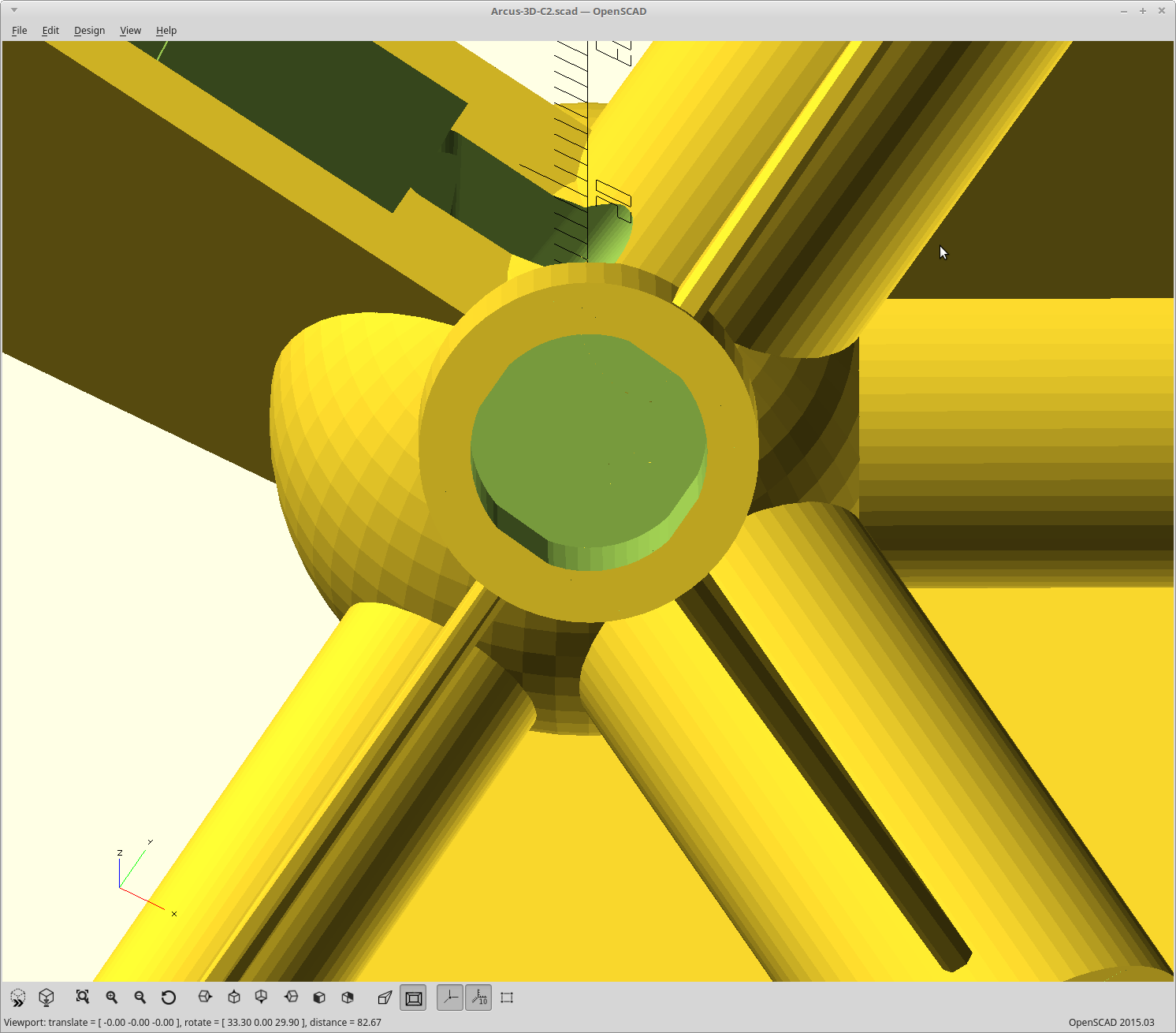
Hi Daren, it is not clear how to interface with a standard gcode. Ideally to have a piece of SW where the input is the original cartesian gcode and the ouput the translated tripod gcode. Is it possible for you? How do you create  the file ?  Thanks a lot!

  Are you sure? yes | no

gbdb71 wrote 07/18/2019 at 19:29 point

Is concept suitable for cnc milling?

Looks like neatly handling heavy weights:

https://www.youtube.com/watch?v=9KMptw7ZgVI

  Are you sure? yes | no

ekaggrat singh kalsi wrote 09/18/2018 at 04:05 point

really great printer and my next printer to build . but i dont see a lot of printed parts pictures or printed part dimension validation . is this project shelved ? did the final printer never work or something else is not resolved?

  Are you sure? yes | no

Daren Schwenke wrote 09/18/2018 at 04:14 point

I got busy, and never got around to finishing it up.  I've resurrected it now, tweaking some stuff to use it as the motion platform for the P1 but stripped out the extruder code in the process.  Less than 2 weeks to go for my self inflicted deadline for that, and then I can add the extruder code back in.

  Are you sure? yes | no

zpyerhnp wrote 02/25/2018 at 20:56 point

I think this is the coolest 3D printer design, and I'm thinking about trying to build one from scratch.

What size motors / torque is needed for a 'normal size' (maybe 6"x6"x6"-ish build volume) 3D printer based on the C1? Can you use very tiny motors because of the mechanical advantage?

  Are you sure? yes | no

Daren Schwenke wrote 03/05/2018 at 03:21 point

The required torque varies depending on where you are in the build area.  The lowest torque requirement is also the most used area... near the bed and in the center.  As you raise the head, the torque requirement will increase. The mechanical advantage you have decreases and the tension on the center spring increases.

The Nema 17 motors/ ~8mm shaft size I picked here gave a good balance of speed/accuracy and had at least 2x the required torque for the entire build area.

So yes, you could get away with less.  Probably a lot less.  You could also just use smaller spooling shafts to increase the torque, but that will start to cost you top speed then. 

  Are you sure? yes | no

Steven wrote 10/21/2017 at 21:23 point

Keep up the great work! I'm checking back daily to see how its going and I cannot wait to see it move and then print!

  Are you sure? yes | no

Daren Schwenke wrote 10/22/2017 at 01:44 point

Me too!  It's so close..

However, I'm out of time for Teen Groot so I have to switch gears for a day or two until I can wrap that up.  https://hackaday.io/project/27573-teen-groot

  Are you sure? yes | no

Idris wrote 10/21/2017 at 13:20 point

Great project.
I'm looking at your pulleys and virtual inverted pulleys and thinking about wear on the thread how smoothly they run over the surface of the plastic.

I came across ceramic thread guides for sewing machines on aliexpress, I wondered whether they might make for a smoother surface for the thread to run over?

https://www.aliexpress.com/wholesale?catId=0&initiative_id=SB_20171021051322&SearchText=thread+guide+ceramic

  Are you sure? yes | no

Daren Schwenke wrote 10/21/2017 at 15:25 point

That's pretty neat.  I'd have to think about how that would affect the math due to the increased hole size unless you used a pair and put a set them after the top pulleys.  With the forces involved I imagined printing them out of nylon would have helped greatly too. Problem was when I did the entire end effector out of nylon, it wasn't stiff enough so they would have to be 'drop in' like your ceramic guides anyway.  Alternately the M2 (https://hackaday.io/project/20763) could have actually printed them as a single part in a gradient blend, but I wanted to keep this project accessible. 

The existing lower virtual pulleys don't get any translation movement so I'm hoping the lubricity of the line is enough to prevent significant wear for a while.  

I'll run it until it fails and we'll see what happens.  :)

The line itself is cheap to replace and 110 yards was enough to replace them all 7x for the original $9 spent, but I imagine the top of the virtual pulleys themselves will wear as well and need replacing along with the lines.

It's gotta move on its own first.  :)

  Are you sure? yes | no

Idris wrote 10/22/2017 at 11:15 point

I was thinking you could remove the pulleys entirely and have the same geometry both at the top and bottom of the thread, I think that would eliminate the wrapping/unwrapping length changes but also remove any issues with the thread leaving the pulley at an angle when the effector isn't centred.

  Are you sure? yes | no

Walter Schreppers wrote 10/13/2017 at 15:50 point

How does moving up in z-layers work on this one? Move the entire printer up?

  Are you sure? yes | no

Florian Festi wrote 10/13/2017 at 18:57 point

It works similar to a delta printer. Pulling in string on all three winches moves the end effector up.

  Are you sure? yes | no

Hacker404 wrote 10/12/2017 at 20:33 point

Love it!

You should be able to make the effector end of the cable connection wrap around a pulley shaped contour to get a mathematical fixed point equivalent by the effects of the contour canceling out the effects of the pulley.

Also there was a very old product that is still available called "Dial cord" that would be a good replacement for the fishing line.

+10, I would like to see the code for the kinematics when it's done, if you are going to release it.


  Are you sure? yes | no

Daren Schwenke wrote 10/12/2017 at 20:51 point

Great minds.. Just did that like 2 days ago: https://hackaday.io/project/26938-arcus-3d-c1-cable-printer/log/68555-virtual-inverted-pulleys-yep

Tripod kinematics without pulley compensation (which I don't need anymore) is already part of Machinekit and open source: https://github.com/machinekit/machinekit/blob/master/src/emc/kinematics/tripodkins.c

  Are you sure? yes | no

Sancho_sk wrote 10/12/2017 at 19:03 point

This is amazing. Thanks to the construction, this might be scaled up to real-life building printer. With the "flat pack" ability it can be transported by a regular truck. WOW!

  Are you sure? yes | no

Daren Schwenke wrote 10/12/2017 at 19:49 point

With an end effector of sufficient weight, just the six cables will do and you don't need the push-rod.  That is another one of my work in progress printers already.  :)  Yes, building printing.  Plan is once the ABS part of that one is working, modify it to do super-critical CO2 foam extrusion.  Spray/fill that with concrete, and you have a building.

All the hardware is on the print head for that one.  All the parts for that one including the controller are designed, fitted, printed and done, but I haven't had the time to post anything about it or do final assembly and testing yet:  https://hackaday.io/project/20082-arcus-3d-e1-elephant-printer

  Are you sure? yes | no

Florian Festi wrote 10/11/2017 at 19:25 point

I wonder if disassembly and assembly would be easier if you made hinges (or ball joints) at the end of every second of the vertical beams. You could then remove the other three and then just fold down to top triangle onto the bottom one without disconnecting them.

If you manage to have the other ones also with hinges at the ends but also one in the middle you could fold and unfold the printer in seconds.

Not sure if this compromises stiffness (and ease of construction) too much. But as stiffness is created by the geometrical form and not the stiffness of the corner pieces that might just work.

  Are you sure? yes | no

Daren Schwenke wrote 10/11/2017 at 19:49 point

Every other joint pivoting down may work, and you could put a pin on the other joints to fold that one down too.  I imagine it would sacrifice a lot of rigidity to do it, but it is way more rigid than it needs to be right now.  Pivoting/twisting down would line up the rails nicely.  Those joints would be under a lot of stress though if you didn't keep the top parallel to the base while doing it.

I thought about folding before, but I was removing the top rails for it. This was of course incompatible with the later requirement of screwing down the steppers.

  Are you sure? yes | no

Florian Festi wrote 10/11/2017 at 09:08 point

To avoid creating a mess when disassembling the printer you could add small sponges or silicone lips to press on the curled up string. That way it does not unwind or go on top of itself when you remove the string tension.

You could even have them snap on the winch for disassembly only.

  Are you sure? yes | no

Daren Schwenke wrote 10/11/2017 at 13:18 point

That's a good idea too.  Running them up and down tends to realign the wraps if you are careful about limits, but not having to do that at all would certainly be better.  Sounds like a project for my spool of TPU.  I was happy I got to use it for the vibration isolators in this project already.

If I had software based current control on my steppers, I could lower the current to barely moving and just run them to retract the lines fully.  The upper line would also extend all the way, and then start wrapping in the same direction as the lower lines retracting it as well, mostly.  But that would mean using AMIS-30543 or other software controllable chips at $20 each.  Probably not the target market for this level of printer.

  Are you sure? yes | no

brz.tomek wrote 10/11/2017 at 20:50 point

I am not sure I agree- it is not hard to get software controllable chips at $10/ea. The TMC2100 to start, but also just the fact you can run a filtered signal to the Vref of a SD5984 or DRV8825 also gets you software controllable current. The way many repraps do it is to use an SPI configurable digital potentiometer to set the Vref.  Is this helpful or did I misunderstand the situation?


  Are you sure? yes | no

Daren Schwenke wrote 10/11/2017 at 21:01 point

I probably just didn't look hard enough.  I'm looking for the 2 amp range of output.  I never tried feeding vref into chips.  If you can gang them, then it just adds a cap and two resistors to get a nice stable output for all.  Something to think about.

  Are you sure? yes | no

Florian Festi wrote 10/09/2017 at 09:55 point

Wrt homing:

You can press a bead on one of the strings at each winch e.g. a fishing weight. Then have a micro switch near the top idler with a hole in a lever the string runs through. The bead needs to be positioned that the switch is triggered as the very end of the movement. The distance between the idlers on top and the winch should be less than the maximum travel distance of the machine axis.

To do the actual homing I fear there is not way around jogging the machine axis manually to some extend. What ever you do automatically might move you out of the working volume if the machine starts at the wrong place. With the end stops you at least do not need to drive to a precise location to do the homing fully manually. You could have a parking position e.g. in the middle of the bed that you have to drive to and then run the homing program automatically from there. Being off at the parking position by a few milimeters is probably not problem.

  Are you sure? yes | no

Daren Schwenke wrote 10/09/2017 at 14:09 point

I like that idea.  

Homing will still have to start with the effector an approximately set distance above the bed in the center to avoid bottoming out during homing.

Then for each axis home to the opposite bottom corner, which will pull the push-rod line in to it's lower limit, and then return it to the central raised start position. 

Machinekit should do this out of the box by setting HOME_OFFSET to the homed to line position, HOME to the center raised position, and HOME_SEQUENCE to an incrementing number. That will work.

  Are you sure? yes | no

Florian Festi wrote 10/09/2017 at 14:28 point

Well it depends on whether you have the end stop at maximum or minimum length of the cable. But you can still start at the bottom as the parking position if you want to give out cable. Just move up a bit from there as part of your homing sequence. We are going to need a custom homing code anyway as you need to change the length of the other two cable pairs. Otherwise you can't reach the outer boundaries of the build volume.

  Are you sure? yes | no

Florian Festi wrote 10/09/2017 at 09:42 point

One way around the maths problem would be to just make sure the string always leaves at the same point by funnelling it through a hole only slightly bigger than the string diameter.

I built a styro foam cutter a while ago also using fishing lines. There we routed the string just through eye hooks without any problems. So there is no reason to be afraid of the friction. Especially if the bulk of the change of direction is still handled by the ball bearings.

This is not a beautiful solutions but might just work.

  Are you sure? yes | no

RigTig wrote 10/09/2017 at 11:30 point

Nice idea, Florian. Certainly been used on some 2D printers (drawing machines on strings), where motors are at the bottom of the (nearly) vertical board and run up to the top before going to the gondolier.

One question to think about is whether the error caused by the offset around a winding core is significant enough to warrant a patch. I suspect that the difference between the 'perfect' calculation and the approximate one might be less than the extruder nozzle diameter for all locations but a few extremes.

  Are you sure? yes | no

Daren Schwenke wrote 10/09/2017 at 13:53 point

Some quick math says the winding core will only introduce an error of up to 0.012mm at the extremes as designed.  However, the pulleys at the top can introduce an error of up to 6mm.  I'm ignoring the core, correcting for the pulleys.

  Are you sure? yes | no

Daren Schwenke wrote 10/09/2017 at 14:07 point

I built a prototype using zip ties, eyelets, and wooden dowels to try to find an alternate cable routing which would minimize the difference in line length between the extension of the pushrod lines and the retraction of the lower lines.  The best solution I came up with was also the simplest with just extending the pushrod a little.  It also taught me that the eyelets tended to stutter and grab when I increased the tension in the lines.  

Granted I didn't have pulleys at all for my 'prototype', which would probably reduce this tendency a lot.

Higher tension becomes more important at the extremes as the angle of influence of an axis will be reduced.  So I'm looking for the mathematical solution first.

  Are you sure? yes | no

RigTig wrote 10/05/2017 at 06:56 point

Definitely looking forward to see this design come to fruition. My own efforts have been very slow, having started several years ago (see Rigtig's Big 3D Printer here on HaD- https://hackaday.io/project/13420-rigtigs-big-3d-printer).

Another design, called HangPrinter, has the string motors on the effector: there's a link to it in comments of my HaD stuff. I found the source at https://github.com/tobbelobb/hangprinter. I remember tobbelobb describing adjustments to calculations for string lengths depending on how full the reels are, so there might be a clue or two in there.

I haven't seen any broad-based driver for triangular printers (Cura, Repetier, etc) but as long as the GCODE interpreter handles the basics, any driver can be used. Just make sure that you are inside the triangle. 

If you'd like any hints from me, either PM or just comment here. 

  Are you sure? yes | no

Daren Schwenke wrote 10/05/2017 at 07:18 point

Using Machinekit, tripod kinematics is part of the standard stuff. Have not built that part of the config yet, but it should work fine when I do.  Homing will be interesting and I have no idea there yet.

The first battle was getting Machinekit working at all on the BBGW (for my other WIP 3D printer, the E1).  It also has everything on the print head, but is pellet fed like a Lyman extruder turned on end.  I haven't really documented it here yet, and it's mostly done, but completely untested and may very well meltdown on first power up.  3D printing a Lyman comes with issues.

Problem was only the newer kernel supported the wifi chip and the flavor of Xenomai Machinekit used would not work there.  Finally got an rt-preempt build running on the newer kernel a few weeks back and Machinekit works now..  Virtually the same config will run this, and this is more likely to work the first time, so starting here.

  Are you sure? yes | no

Similar Projects

Does this project spark your interest?

Become a member to follow this project and never miss any updates