A limited number of the extra badges are available on Tindie.
General description and firmware functionality
Other sections :
- Firmware hacking and adding new applications
- Bootloader
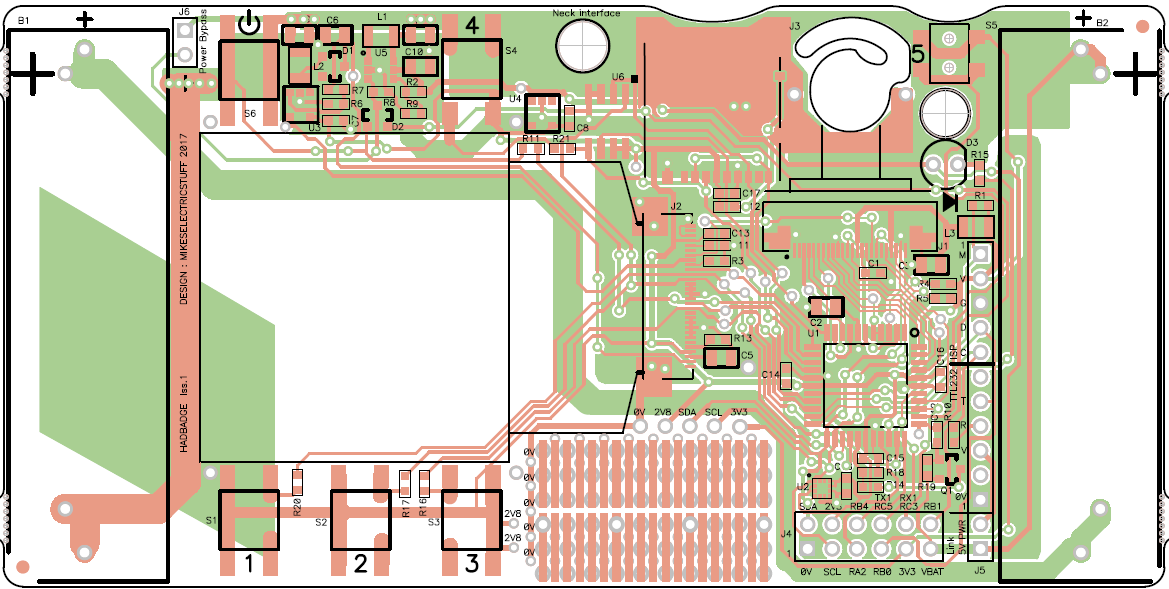
- Hardware Description
- Hardware hacking
- Badge hacks list
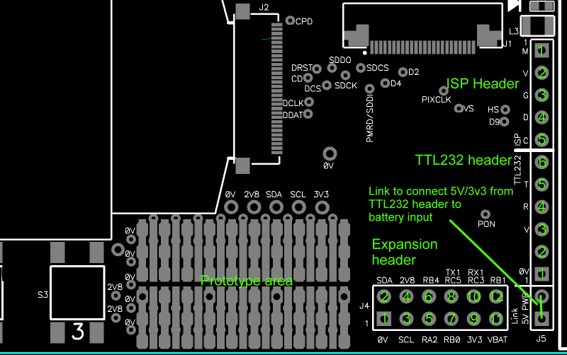
Button numbers and header locations
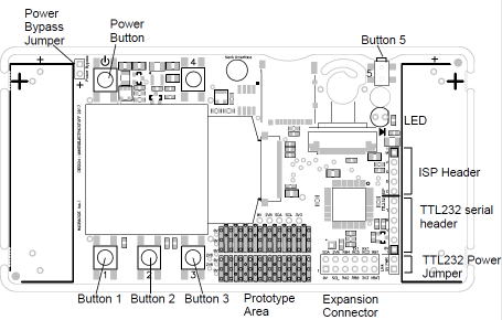
Power control : Pressing the power button turns the badge on. Pressing and holding a couple of seconds turns off.
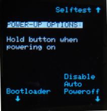
Holding the power button at startup will display all the power-up button functions.
Auto powerdown : the device will power down if no button is pressed, or no significant accelerometer movement is detected for 10 minutes.
Holding button 3 on powerup disables the powerdown timeout. Holding button 4 on powerup performs a hardware selftest (see later).
Splashscreen : At startup, if SPLASH.AVI exists on the card, it will be played once. Embedded framerate is ignored -it plays at maximum rate. This should be a short file to avoid excessive startup delays. If SPLASH.AVI does not exist, it looks for SPLASH.BMP and if present, displays it for a second or so.
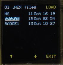
At startup, a menu is displayed allowing selection of various applications.
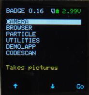
The menu screen also shows the battery voltage ( coloured green, yellow or red to show status), and a card symbol to indicate when a MicroSD card is inserted and successfully mounted.
MicroSD card support : FAT16 or FAT32, no long filename support.
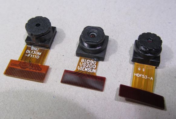
Camera application
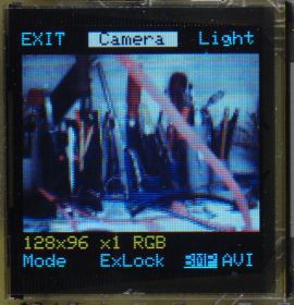
Displays live camera image.
Button 1 selects the recording format (resolution, zoom, colour/mono).
Button 2 locks the camera's auto-exposure value
Button 3 toggles between still ( BMP) and video (AVI) recording.
Button 4 Toggles the illuminator LED
Button 5 takes an image, or starts AVI recording, and stopped with any button.
Images are stored in the CAMERA folder, Videos are stored in the CAMVIDEO folder. (folders will be created if not present) The filename will be the first unused name in the form "CAMnnnn.BMP" or "CAMnnnn.AVI", where nnnn is a number. If you delete files, new captures will be given the number of the deleted file(s) until the "gap" closes.
File formats :
- Saving BMP : resolution 128x96, 8 bit mono or 24 bit colour ( expanded from 565),
- Saving AVI : resolution 128x96, 8 bit monochrome or 16 bit RGB565
- Higher resolutions, using SPI SRAM to expand memory is currently under investigation.
Video framerates : 128x96 Colour 3-10fps, mono 5-16fps. Zoomed modes will have slightly lower framerates. Rate is extremely dependent on teh individual SD card. Frame rate in AVI file will be set to the avarage capture rate measured over the whole recording, so should play back at similar speed to recording, but may have occasional "lumps" due to SD card timings.
Initial testing of SD cards shows that smaller cards (256MB and below) can be substantially faster, with write speeds up to 330KBytes/sec, vs. 80-150Kbytes/sec for larger (512MB+) cards. The utilities application has a speed tester to allow quick selection of cards for maximum speed.
Note that all camera modes crop an image from the whole sensor area, but the camera's auto-level control acts over the whole sensor, therefore bright lights outside the field of view may cause the exposure to be significantly non-optimal. This effect will be more noticeable in the zoomed modes, where a smaller part of the sensor is visible.
File compatibility with software packages.
** PLEASE ** let us know in comments about non-Windows software options.
Sample files are included in the files section.
VLC (Windows and Android) : Plays monochrome...
Read more »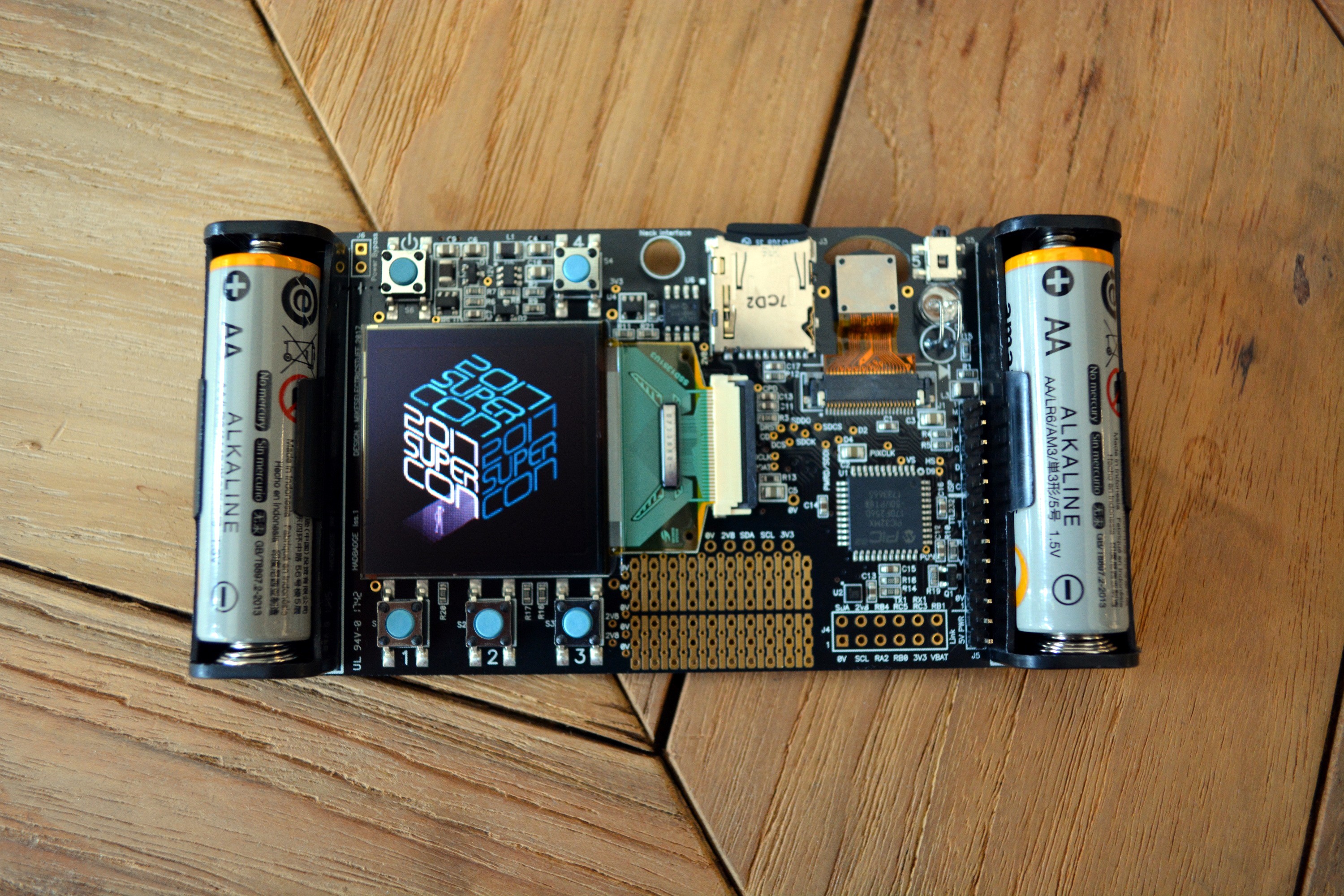


 Sebastian
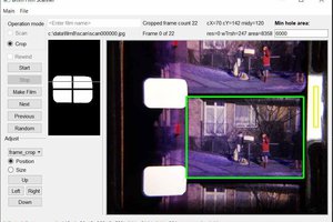
 Lars Lund Hansen
 Ethan Durrant
 jaromir.sukuba
Hey all, I dug out my badge last week to mess around with it and the screen seems to have died. I didn't store the badge with batteries installed and I tried out fresh batteries just to make sure it wasn't a power issue. The reason I think it's the screen is that the "flash blub" still does it's thing when you turn it on. Any recommendations for things to check and/or a process to follow to troubleshoot the issue would be extremely appreciated.