 allai5
-
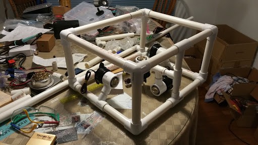
1Creating the Frame
Materials:
- 1 10 ft. 0.5” ID PVC pipe
- 6 0.5” ID PVC tee connectors
- 8 0.5” ID PVC 3-way elbows
- 4 500 GPH Johnson bilge pump motors
Equipment:
- Marker
- Dremel
- Ruler
- Drill with 0.75” drill bit
Note: PVC cement should be applied to piping prior to all connections.
- Using the ruler, measure two 17” lengths of PVC from the 10 ft. PVC pipe, and mark at the appropriate dimensions.
- Use the dremel to cut along the marks.
- Insert a 3-way elbow at either end of each 17” PVC pipe.
- Measure two 11” lengths of PVC, and use the dremel to cut along the marks.
- Use the two 11” PVC pipes to connect the two 17” pipes via the 3-way elbows. This will create a rectangular structure.
- Measure two 11” lengths of PVC, and use the dremel to cut along the marks.
- Attach each of the 11” PVC pipes to the two 3-way elbows at the top of the rectangular structure.
- Attach a 3-way elbow at the unoccupied end of each 11” PVC pipe.
- Measure four 5” lengths of PVC, and use the dremel to cut along the marks.
- Connect two of the 5” PVC pipes using a tee connector, and repeat for the other two 5” pipes.
- Connect each paired PVC pipe structure to the two 3-way elbows at the bottom of the rectangular structure, so that the tee connectors point toward each other at 45 degrees above the horizontal.
- Attach a 3-way elbow at the unoccupied end of each paired PVC pipe structure.
- Measure two 11” lengths of PVC, and use the dremel to cut along the marks.
- Connect an upper unoccupied 3-way elbow with its corresponding lower unoccupied 3-way elbow using a 11” PVC pipe. Repeat on the other side.
- Measure four 8” lengths of PVC, and use the dremel to cut along the marks.
- Connect two of the 8” PVC pipes with a tee connector, and repeat with the other two 8” pipes.
- Secure one of the paired PVC pipe structures in between the upper unoccupied 3-way elbows, so that the opening of the tee connector points directly downwards.
- Secure the other paired PVC pipe structure in between the lower unoccupied 3-way elbows, so that the opening of the tee connectors points directly upwards.
- Measure two 4” lengths of PVC, and use the dremel to cut along the marks.
- Connect the two 4” PVC pipes with a tee connector.
- Secure the paired PVC pipe structure in between the two tee connectors pointing towards each other, so that the opening of the tee connector of the newly paired PVC pipe structure points into the frame.
- Measure one 3” length of PVC, and use the dremel to cut along the marks.
- Insert the 3” PVC pipe into the final opening of the tee connector pointing into the frame.
- Attach a tee connector to the unoccupied end of the PVC so that the bottom of the “T” points downwards.
- Mount the four motors to the frame by securing them to the openings of the four unoccupied tee connectors.
- Drill 0.75” diameter holes into the PVC pipe in between in each set of connectors.
![]()
![]()
-
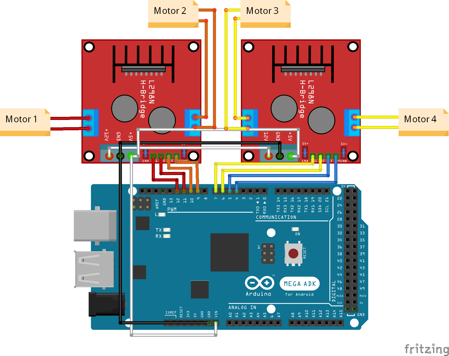
2Creating the L298n Circuit
The primary purpose of the circuit on our ROV is to take input from a program and use this input to control the motors.
- Obtain 2 L298n motor controllers.
- Connect the 12 volts and ground to the two terminals.
- Connect the 5 volts terminal to the Vin pin on the Arduino Mega
- Connect the pins on the first L298n as so:
U4 to Digital Pin 7
U3 to Digital Pin 6
U2 to Digital Pin 5
U1 to Digital Pin 4
- Connect the pins on the second L298n as so:
U1 to Digital Pin 9
U2 to Digital Pin 10
U3 to Digital Pin 11
U4 to Digital Pin 12
- Check if the Arduino's and the two L298n's lights are on.
- Sync the XBox controller with your wireless receiver by pressing the sync button on both components.
- Upload the code below to test your program.
#include <XBOXRECV.h> USB Usb ; XBOXRECV Xbox(&Usb) ; int x1; int y1; int a1=2; int a2=3; int b1=4; int b2=5; int c1=6; int c2=7; int d1=8; int d2=9; int a=10; int b=11; int c=12; int d=13; void setup() { // put your setup code here, to run once: Usb.Init() ; Serial.begin(9600); Serial.println("yo"); pinMode(a1,OUTPUT); pinMode(a2,OUTPUT); pinMode(a,OUTPUT); pinMode(b1,OUTPUT); pinMode(b2,OUTPUT); pinMode(b,OUTPUT); pinMode(c1,OUTPUT); pinMode(c2,OUTPUT); pinMode(c,OUTPUT); pinMode(d1,OUTPUT); pinMode(d2,OUTPUT); pinMode(d,OUTPUT); } void loop() { Usb.Task() ; if (Xbox.XboxReceiverConnected) { x1=Xbox.getAnalogHat(LeftHatX , 0); y1=Xbox.getAnalogHat(LeftHatY , 0); //speed = Xbox.getAnalogHat(LeftHatY , 0) / 128 ; //speed = -Xbox.getAnalogHat(LeftHatY , 0) / 128 ; if (x1>9000){ digitalWrite(a,HIGH); digitalWrite(b,HIGH); analogWrite(a1,x1/128); analogWrite(a2,0); analogWrite(b1,0); analogWrite(b2,x1/128); Serial.println("1"); Serial.println(x1/128) ; } else if (x1<-9000){ analogWrite(a,x1/128); analogWrite(b,x1/128); analogWrite(a1,0); analogWrite(a2,255); analogWrite(b1,255); analogWrite(b2,0); Serial.println(x1/128) ; } else{ digitalWrite(a,LOW); digitalWrite(b,LOW); analogWrite(a1,0); analogWrite(a2,0); analogWrite(b1,0); analogWrite(b2,0); } } }![]()
-
3Topside Electronics Box
**Note: The final electronics box is based off of the SeaMATE TriggerFish ROV’s topside electronics box.
- Follow the instructions in the following PowerPoint.
- https://docs.google.com/presentation/d/1dUtlIbWnvZd3Ftoe-ubnQnERUswa4mzj8zIySkJgx_E/pub?start=false&loop=false&delayms=3000&slide=id.g1c25bea16e_4_31
![]()
![]()
-
4Tether Management Cross
Finally, create a tether management cross using the SeaMATE PowerPoint linked below: https://docs.google.com/presentation/d/1OqQ49ZD1G6fhgH34ldpA0NPWfAKPs6clWxlLNhh0xcE/pub?start=false&loop=false&delayms=3000&slide=id.g1c265fea39_2_47
To add to this procedure however, put heat shrink wrapping over and 3 layers of silicone epoxy between the wires to ensure a waterproof seal.
-
5Adding a Water Containment Apparatus
Use environmentally friendly duct tape to attach a container to the ROV. This container should be able to be closed and opened easily as it should be able to shipped to a lab for further analysis. We used a water bottle.
-
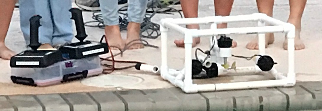
6Finished!
![]()
Volturnus ROV
A low-cost, DIY ROV (Remotely Operated Vehicle) to detect marine pollution in local communities.


Discussions
Become a Hackaday.io Member
Create an account to leave a comment. Already have an account? Log In.