Close
0%
0%

Build your own panel meter

panel meter design using a 16x2 LCD and a MSP430

Similar projects worth following
Despite the fact that the market is full with these devices and they don't cost more than 2$ most of the times, there will always be the "can I build it myself" type of question that will continue to buzz me. So here we are, discussing a panel meter schematic into its details.

To build or not to build?

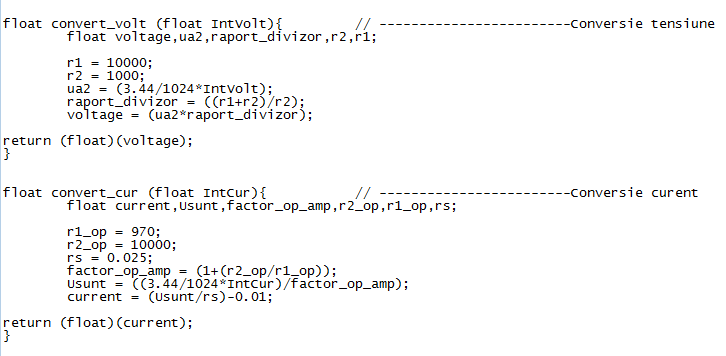
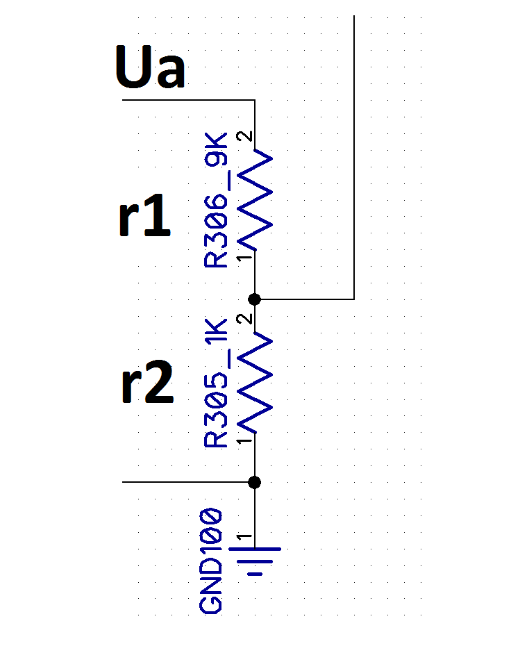
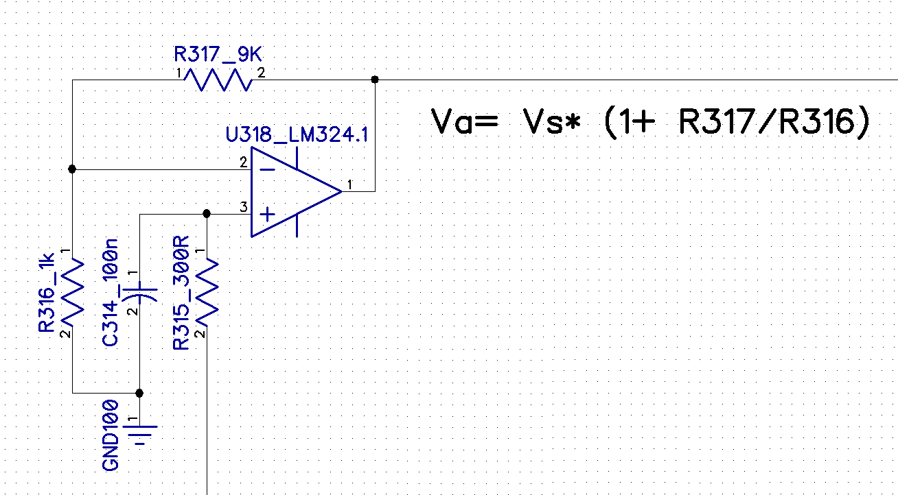
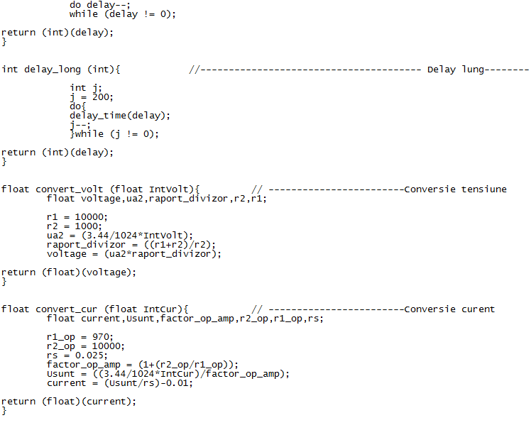
Why would I want to build it myself instead of buying one? Well, first of all, is a good exercise to realize exactly what's inside of an electronic voltmeter and ammeter, then is the practice of writing some c++ code that will integrate the mathematical formulas for the shunt and for the voltage divider.

Challenge

If i was about to build this device, I wanted it to be able to read voltages between 0 and 40V, currents up to 10A and to achieve a low power consumption. I wanted to obtain a good precision and to have the possibility of calibrating the device.

Advantages of having a device you built

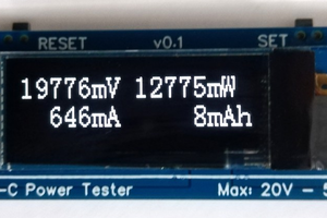
-Having a device that you built, is always good because you can personalize it. You can put your name on it, you can display other messages, you can choose your own display colors, you can create your own font, etc...

-You can display the desired range, number of decimals, and particular order of your readings. You can make personalized measurements (as power readings at certain voltages). You can display warning or error messages if some readings are exceeding certain values. You can program it to display min/max values at your choice, depending of your needs and your applications. 

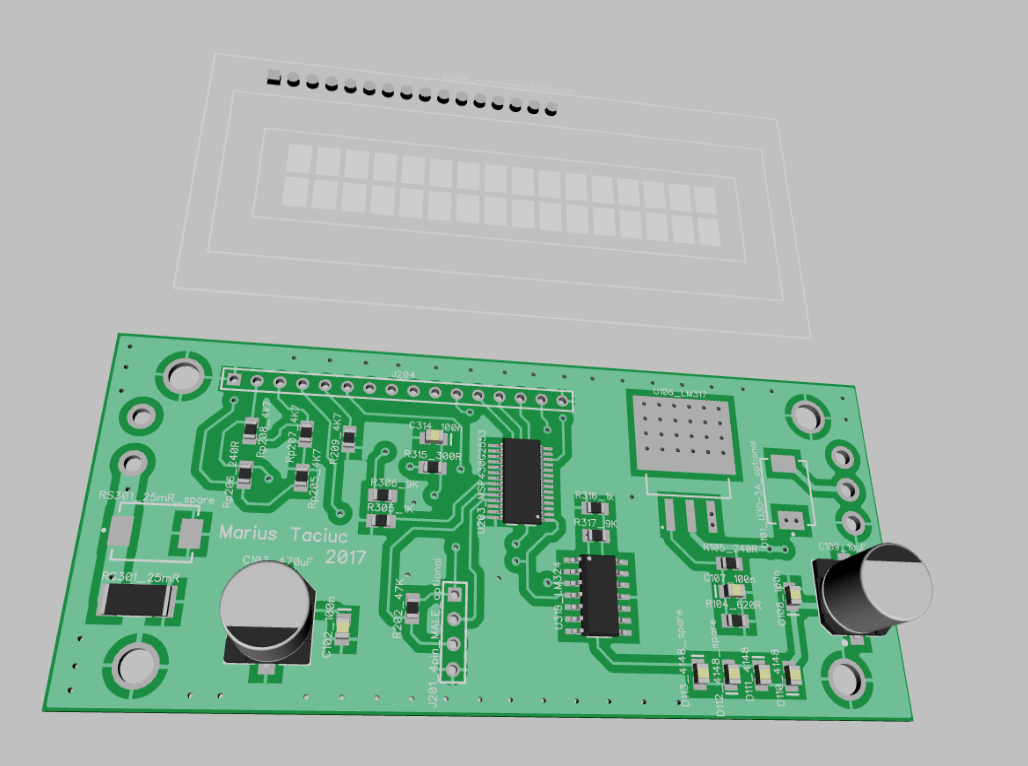
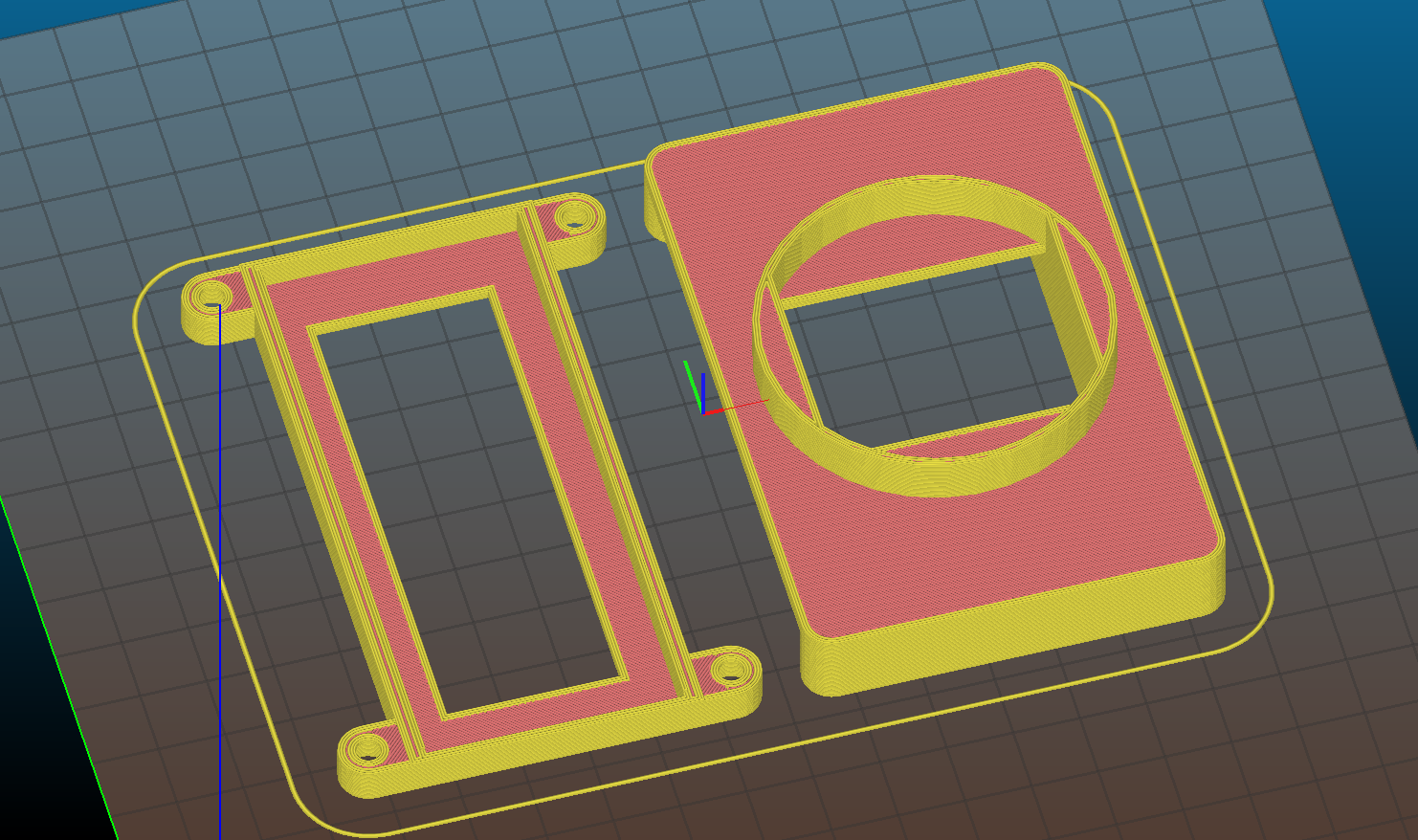
-You can make a design that is perfectly adapted to your needs. 

-It is a good exercise and you can learn a lot from building it. It takes you back to the school years of designing and calculating a shunt, calculating the factor of an OpAmp and integrating the values into the MCU through the ADC. It is a lot of play and a lot of fun.

The case files can now be downloaded from here:

https://cults3d.com/en/3d-model/tool/16x2-lcd-panel-meter-case

A2 Firmware version.txt

Updated A2 Firmware version

plain - 17.27 kB - 12/02/2017 at 01:37

Download

pcb render.png

PCB render descriptive image

Portable Network Graphics (PNG) - 224.49 kB - 11/28/2017 at 23:48

Preview
Download

main_pannel_meter.cpp

Attached software

cpp - 15.68 kB - 11/28/2017 at 23:43

Download

Pannel meter.dip

Layout for the panel meter PCB

dip - 336.37 kB - 10/19/2017 at 03:45

Download

Pannel meter.dch

Schematic for the panel meter PCB

dch - 243.73 kB - 10/19/2017 at 03:45

Download

  • 1 × MSP430G2553 TSSOP Microprocessors, Microcontrollers, DSPs / ARM, RISC-Based Microcontrollers
  • 1 × LM317 Power Management ICs / Linear Voltage Regulators and LDOs
  • 1 × LM324 Amplifier and Linear ICs / Operational Amplifiers
  • 2 × 9K resistor
  • 2 × 1K Electronic Components / Misc. Electronic Components

View all 17 components

  • How to calibrate

    Marius Taciuc11/29/2017 at 00:38 0 comments

    The C++ software section responsible for calibrating the device is quite self explanatory.

    Adjust from software the values of the resistors you populated on your voltage divider, then measure the MCU voltage and replace this voltage for the ADC into the formula. 

    For calibrating the current reading, keep in mind that you can easily have some resistance variations on the shunt and this could be because of your solderings and because of the pcb design. So after you made sure you got the OpAmp resistors correctly declared and the ADC voltage, adjust the measurement from the shunt value. This is very sensitive and a simple change from 0.25 to 0.259 can mean almost 4%. It helps if you use a good calibrated multimeter that you might have around the shop to gain the actual value of the measured current. And since we're talking about multimeters and the accuracy of a good multimeter for calibrating this thing, I will take the liberty of attaching this review I made some time ago:

  • Average for sampled values

    Marius Taciuc11/29/2017 at 00:01 0 comments

    The ADC returns an integer value and making an average between the last 8 or ten acquired values, can return in the end a float value and the result can be that you can display an accurate value on the display and you can even do so adding some decimals. This comes really handy with displaying some mA.

  • Added C firmware

    Marius Taciuc11/28/2017 at 23:47 0 comments

    I added the C code into the Files area. Stay tuned for more details and instructions on how to calibrate the meter according to your resistor values and MCU voltage.

  • Added schematic and layout for the PCB

    Marius Taciuc10/19/2017 at 03:48 0 comments

    Check the Files area to see and download the schematic and layout files for the panel meter PCB

    This is actually the second iteration of the PCB. At first I used one of the PCB's that I had from the Scorpion 3.0 project. I trimmed the extremities of the PCB and used only the middle part with the MCU, OpAmp shunts and regulator. I wrote the first version of software using this refurbished PCB and then I redesigned the entire thing. 

View all 4 project logs

  • 1
    Printing the case

    I added the STL link somewhere above and I used the following settings:

    - 0.3mm layer hight

    - 3 shells

    - 3 top layers

    - 3 bottom layers

    - 10% honeycomb infill

View all instructions

Enjoy this project?

Share

Discussions

Zoltán wrote 02/15/2023 at 00:05 point

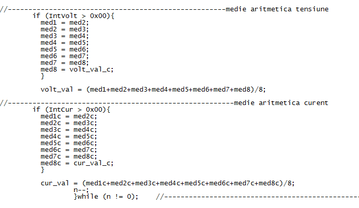
A less ugly way of averaging eight(or more) integers

int x=0;

for(int 0; i<9; i++){

x+=whateverfunctiongetsthevalue;}

x=x/8;

  Are you sure? yes | no

Marius Taciuc wrote 02/15/2023 at 06:15 point

Thanks.

  Are you sure? yes | no

Marius Taciuc wrote 10/20/2017 at 00:39 point

Thank you so much for commenting, Martin. I rejoice when somebody minds my crazy designs at all. 

I find it funny when somebody like you takes the time to describe the positives and the negatives of their own ideas. ICL71XX is an old design from the 70's. I'm not saying though, that I'm building something better here and I'm not even trying to beat some other design. Is just that, maybe in some cases, you want to display a message on the screen. In other cases you want different number of digits or different ranges. Maybe you want some cool fonts that you can create yourself. We live in a world where having things functional isn't all. These things must also be good looking and cool gadget like. I wanted for instance to have both, voltmeter and ammeter in one device and the ICL71XX can not provide that.   

About the power consumption, I realize I cannot beat the ICL here. Probably, when it will be finished, this device will take about 10mA to operate. Most of the power will go into the backlight of the display, but that's a choice of each individual user. Everyone of us adds at least a lousy LED on the front panel of their device or of their custom built power supply. You can disconnect the backlight and add a separate LED if this works better for you. My design here, does not take these miliamps from the measured voltage. It has a separate input for that.

  Are you sure? yes | no

Martin wrote 10/19/2017 at 06:27 point

When I hear "panel meter" I think of an ICL7106 or ICL7107. They did not need a line of code to operate and in case of the LCD version required less than 1mA of current.

OK, one drawback was, that it's input common mode range does not go down to zero, so in most cases supply and input voltage had to be isolated. For a car battery display (8-16V) I designed a split voltage divider (taking advantage of the true differential input) to overcome this. Still less than 1mA of current below 14 to 15V.

  Are you sure? yes | no

Similar Projects

Does this project spark your interest?

Become a member to follow this project and never miss any updates