John Sully
-
Back of the line
10/23/2015 at 21:47 • 0 commentsWell I haven't updated in a while because I've been working on a few other things. The coolest is a new C++ editor that prioritizes responsiveness while understanding your code.
I've also been working on a "debuggable" build system called rbuild which I'll be putting up on github shortly.
I do hope to return to this project in the near future. A discrete transistor machine has been a goal of mine for a long time.
-
Searching For Parts
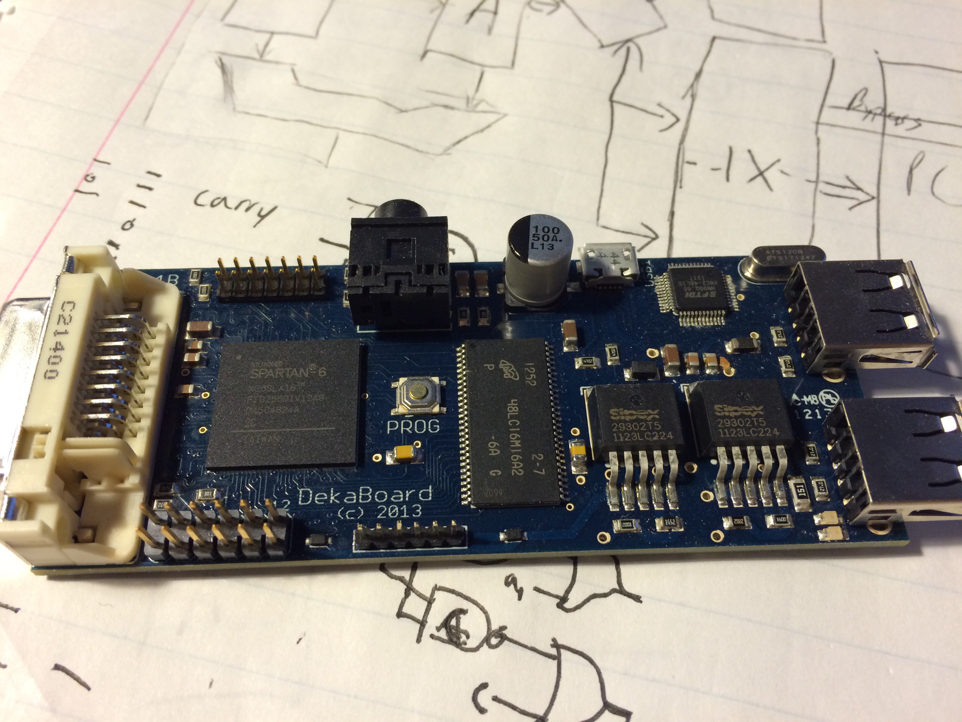
12/19/2014 at 10:29 • 1 commentI was digging through my parts bin today to find some MOSFETs to play with. It turns out I've got nothing! I did find an old project of mine to get sidetracked with, the DekaBoard. This was my attempt to create an FPGA development board for multimedia. Just as I finished it I got a new job and never really had time to do more with it. Maybe I'll get a version of Trinity running on it.
![]()
I think I'll use a DekaBoard for USB keyboard/mice input and DVI output in the final build. One drawback to the Dekaboard is the lack of I/Os. It was always intended to use high speed serial I/O - but I could always build a shift register breakout board for this. I'll have to level shift the trinary logic levels anyways.
On an unrelated note, the dreary weather outside has inspired me to create a sinister looking Logo for the machine. I think it will look sharp on it's front panel.
![]()
-
Assembler and Emulator Source Now Public
12/19/2014 at 06:28 • 0 commentsI uploaded the assembler and emulator source code to github. Try it out and let me know if it works for you. I omitted a build script as its only one .cpp file for each. The code was written and tested on windows, but as a simple console app it should work on any platform with little modification.
Try it out: https://github.com/JohnSully/Trinity
A disclaimer on the code: I wrote this quickly over the weekend and hacked it mercilsy to try new stuff. Its not the cleanest code but it works.
I also took some time to modify the jump instructions. JAF has now been replaced with JEQ, JEZ, and JMP. The new "ABC" program is much simpler:
; Outputs A,B,...,Z in a continuous loop
;Setup
Start:
    LIM    '@'    ; 'A'-1
Loop:    SWP
    LIM    1
    ADD
    OUT
;Check if done
    SWP
    LIM    'Z'
    SWP
    JEQ    Done
    JMP Loop
Done:
    JMP Start
And assembled:
000000: 00+--+ 0+-+0+ ;LIM 0+-+0+ 0000+-: 00+--0 ;SWP 0000+0: 00+--+ 00000+ ;LIM 00000+ 000+--: 0000+- ;ADD 000+-0: 00+-00 ;OUT 000+-+: 00+--0 ;SWP 000+0-: 00+--+ 0+0+00 ;LIM 0+0+00 000+0+: 00+--0 ;SWP 000++-: 000+-- 0000+- ;JEQ Done[0]:(0000+-) 000+++: 000+-+ 000--- ;JMP Loop[0]:(000---) 00+--0: 000+-+ 00-+0+ ;JMP Start[0]:(00-+0+) -
2 Transistor Carry Function
12/18/2014 at 06:24 • 0 commentsI've been spending some time thinking about my implementation of the ternary full adder. This website has been very helpful with working out the design but I was discouraged with the large number of gates involved. My initial estimates were somewhere in the order of 30+ transistors per trit, which would ultimately make the whole adder close to 200 transistors. Constructing this with discrete components would be very tedious so I wanted to see if I could economize somewhat.
Theory of the Carry Function
I started out by taking a closer look at the carry function. The inputs to the carry function are the previous carry, and the bits of our two operands. Looking at the truth table I noticed it could be easily simplified:
++0 = +carry, --0 = -carry
+++ = +carry, --- = -carry
++- = 0carry, --+ = 0carry
00X = 0carry
This property holds for all permutations. In English the function for the carry is: of the 3 inputs at least two must agree, and none may dissent.
An Idea
Normally you would construct this with a combination of gates, but I started to wonder if I could build a circuit where the dissenter would "pull down" (or up), the sum to something close enough to zero that the output transistors would turn off. Essentially doing some of the computation in an analogue circuit.
The design I came up with is a passive mixing circuit feeding into a ternary NOT gate which acts as our output buffer. This computes the inverse of the carry function but another NOT gate on the output would easily correct that. With the passive mixer each input's voltage is effectively divided by a third and summed with the others. So assuming +/-5 signalling: +5, +5, +5 inputs sum to: 5/3 + 5/3 + 5/3 = 5.
An interesting thing happens when they start to diverge though:
5/3 + 5/3 + 0/3 = 3.33V
5/3 + 0/3 + 0/3 = 1.66V
5/3 + 5/3 + -5/3 = 1.66V
That 1.66V is important. With ideal MOSFETs that 1.66V would be treated as positive by the gate. But real MOSFET transistors are not linear, they usually have some initial resistance and don't start reacting until around 2 or more volts. That means our 1.66V will be effectively rounded down to zero giving us the output we need.
Implementation
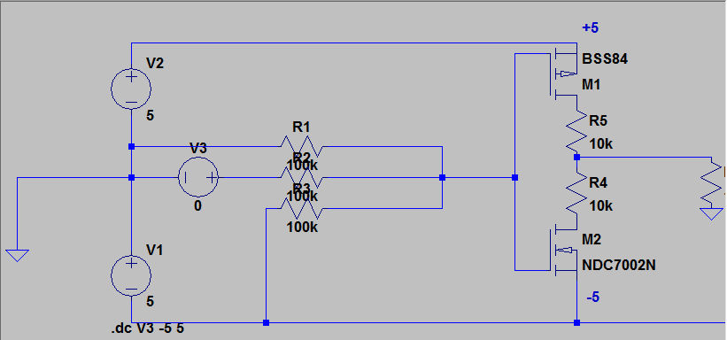
Given that we can design and simulate the circuit in LT-SPICE:
![]()
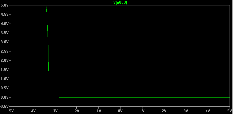
The left of R1, R2, R3 are the inputs to our logic gate. For the simulation R1 is wired to logic 0, R3 to -5V, and R2 to our voltage source V3. Sweeping V3 from -5 to +5 volts we get the following output:
![]()
We can see on the left that as R1, and R3 are both at -5V they are "agreeing". The output is +5 volts due to the inverter used as our output stage. Another inverter would return this to the correct -5 volts. As V3 sweeps closer to logic zero and "abstains" just as R1 is doing; we no longer have enough voltage into M1 and as the transistor turns off it quickly reaches equilibrium with M2 keeping the output at 0 volts - just as we want. As V3 progresses to +5V it effectively cancels out R3 giving a true 0V to our inverter and we remain at 0 volts for the output.
The graph is nearly perfectly mirrored when simulating with positive R3 at +5 volts.
Drawbacks
This design is not without its downsides. Ideally you'd like your gates to have infinite input impedence and zero output impedence. The passive mixer drastically lowers our input impedence to near 100K. This combined with the already high output impedance of our inverter circuit means this gate will be hard to drive. This will likely have a negative impact on the speed we'll be able to operate this gate at, as well as waste power. This also puts constraints on the voltage our logic can operate at. A 5V range with +2.5/-2.5 is not high enough to reliably overcome the threshold of our transistors so we need a rather high 10V range of +5/-5. This large range will be more difficult for our transistors to drive.
Conclusions
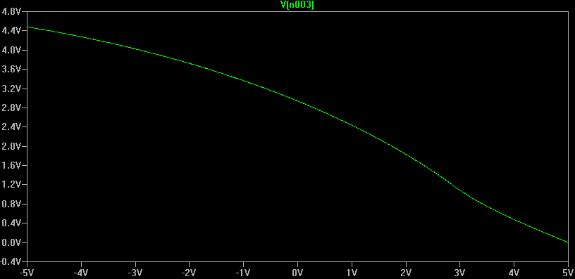
It's important to realize that this only works because we're working with non-ideal transistors. When I first simulated this design using ideal transistors it did not work correctly. This is a pleasant turn of events as normally the non-ideal nature is a significant problem to be worked around. While this gate would never be used in high performance integrated circuits due to the drawbacks mentioned it is very economical. This is exactly what we want when we're building a computer by hand with discrete transistors. If we wanted raw speed we'd be using an FPGA.
Just for fun, the circuit with ideal transistors:
![]()
-
Rethinking Jumps
12/17/2014 at 04:46 • 0 commentsThe JAF instruction is the most important instruction in the whole machine. It is what makes it Turing complete. Unfortunately it is also currently spec'd at 2 operands which makes the implementation much more difficult.
I've been mulling over replacing JAF with a set of conditional jump instructions:
JEQ a==b
JEZ a==0
JMP (unconditional)
These 3 should be hardware efficient while allowing efficient implementations of the two most common loops I expect to see:
Searching for tokens, and for loops.
-
A Bare Essentials Instruction Set
12/15/2014 at 10:20 • 0 commentsI've been a little bit worried about the ease of construction of my 20 instruction ISA, so I've put here a simplified version. This should still be sufficient to get a useable machine albeit with significant performance penalties. At only 11 instructions this design would require much simpler hardware.
Mnmonic Name Operation Arithmetic And Logic NAC Negate Accumulator -A -> A AAC And Accumulator A & B -> A OAC Or Accumulator A | B -> A XAC XOR Accumulator A XOR B -> A ADD Add Accumulator A + B -> A SUB Subtract Accumulator A + (-B) -> A Branch and Test JAF Jump Flags (Indirect) if (op1 & flag) then (PC + 2 + op2) -> PC Load and Store SWP Swap A <-> B LIM Load Immediate op1 -> A IO OUT Output to terminal A -> Term Device IN Input from terminal Term Device -> A This design does not need a stack pointer or an index register. All jumps are relative. Unconditional jumps can be simulated by testing the True flag which is always true. This will likely be the ISA of my first machine but it will make implementing higher level languages tedious and the performance will be poor.
I'm also toying with the idea of some sort of trap infrastructure so I can emulate the missing instructions in software.
-
A Simple Test Program
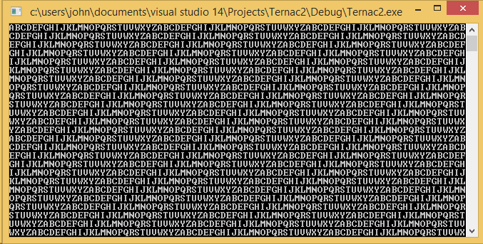
12/15/2014 at 08:43 • 0 commentsNo instruction set is proven until an actual program is written in it. The goal of this program is to ensure the instruction set is both useable and turing complete. The program itself is simple, it prints out its A, B, Cs, and loops back to A after printing Z.
The listing is below:
; Outputs A,B,...,Z in a continuous loop
;Setup: Loads the Loop label into IX so we can jump back to the start of the loop
Start:    LIM    Loop[0]
    SIL
    LIM    Loop[1]
    SIH
    LIM    '@'    ; 'A'-1
Loop:    SWP
    LIM    1
    ADD
    OUT
;Check if done (See if A - 'Z' == 0)
    SWP
    LIM    'Z'
    SUB
    SWP
    JAF    Z,Done   ; If the Z flag is set then jump to Done
    JIX    ; Jump to Loop
Done:    LIM    Start[0]
    SIL
    LIM    Start[1]
    SIH
    JIX
The listing shows a few intersting things about the design. First most instructions have no operands. This should greatly simplify the decoding hardware. Secondly we've introduced the strange [0] syntax to address high and low trites of our double-width registers. This is in contrast to other multi-width architectures like the Z-80 where H and L postfixes were added to the registers.After fixing a large number of bugs in both my assembler and the emulator, the program itself worked perfectly without modification.
The output:
![]()
The assembler is output into a custom "trit" format resembling the old intel hex format. Right now my emulator reads this in directly. Eventually I hope to have a self-hosting loader in ROM that can take these files over the serial port just like my old IMSAI.
000000: 00+--+ 000+0- 	;LIM Loop[0]:(000+0-)
0000+-: 000+++ 	        ;SIL
0000+0: 00+--+ 000000 	;LIM Loop[1]:(000000)
000+--: 00+--- 	                ;SIH
000+-0: 00+--+ 0+-+0+ 	;LIM 0+-+0+
000+0-: 00+--0 	        ;SWP
000+00: 00+--+ 00000+ 	;LIM 00000+
000++-: 000+-- 	        ;ADD
000++0: 00+-00 	        ;OUT
000+++: 00+--0 	        ;SWP
00+---: 00+--+ 0+0+00 	;LIM 0+0+00
00+-0-: 000+-0 	        ;SUB
00+-00: 00+--0 	        ;SWP
00+-0+: 000+-+ 000+00 0000++ 	;JAF Z[0]:(000+00) Done[0]:(0000++)
00+-++: 000+0- 	        ;JIX
00+0--: 00+--+ 000000 	;LIM Start[0]:(000000)
00+00-: 000+++ 	        ;SIL
00+000: 00+--+ 000000 	;LIM Start[1]:(000000)
00+0+-: 00+--- 	        ;SIH
00+0+0: 000+0- 	        ;JIX
The assembler automatically comments the trit listing for easier debugging.
-
Instruction Set Design
12/15/2014 at 08:34 • 0 commentsThe Ternac2's instruction set is rather sparse at a mere 20 instructions and 4 registers. I ultimately plan to build this machine and with the lack of off the shelf ternary ICs I'm expecting to need a lot of discrete components. This means the machine's underlying hardware has to be kept as simple as possible. I think I've come up with a good compromise.
The machine itself has two working registers, the Accumulator and the Operand register. All results from the ALU and Memory units will be stored in the Accumulator. The operand register is intended to be the second operand for any ALU operations needing two inputs. To make the hardware simple the operand register will only be accessible by swapping with the A register. In hardware we'll just rename the two instead of actually moving bits.
The architecture also has two other registers important for higher level languages: A stack pointer and an Index pointer. At 12 trits each these registers will be expensive but I think they will greatly simplify the task of programming. The stack register is necessary for procedural languages, while the index register makes operating on arrays and structures easier.
The final instruction set is below:
Mnmonic Name Operation Arithmetic And Logic ZAC Zero Accumulator 0 -> A NAC Negate Accumulator -A -> A AAC And Accumulator A & B -> A OAC Or Accumulator A | B -> A XAC XOR Accumulator A XOR B -> A ADD Add Accumulator A + B -> A SUB Subtract Accumulator A + (-B) -> A Branch and Test JAF Jump Flags (Indirect) if (op1 & flag) then (PC + 2 + op2) -> PC JIX Jump Index Register IX -> PC Load and Store PSH PUSH A -> [SP++] POP POP A -> [--SP] LSL Load Stack Low A -> SP[0] LSH Load Stack High A -> SP[1] SIL Swap Index Low IX[0] <-> A SIH Swap Index High IX[1] <-> A SWP Swap A <-> B LIM Load Immediate op1 -> A LIA Load Indirect A [IX] -> A IO OUT Output to terminal A -> Term Device IN Input from terminal Term Device -> A