0%
0%
Nixie 'Display of Things'
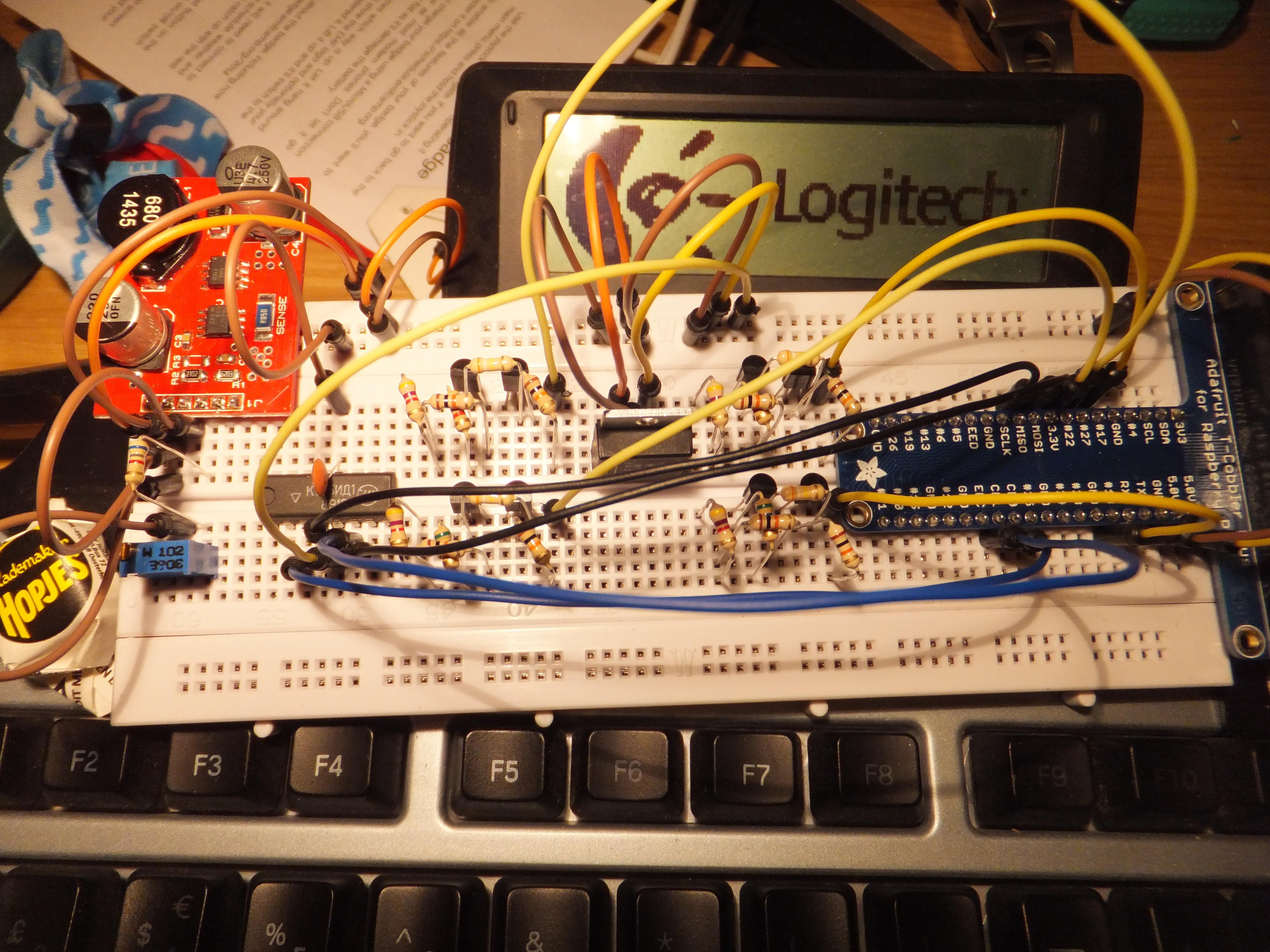
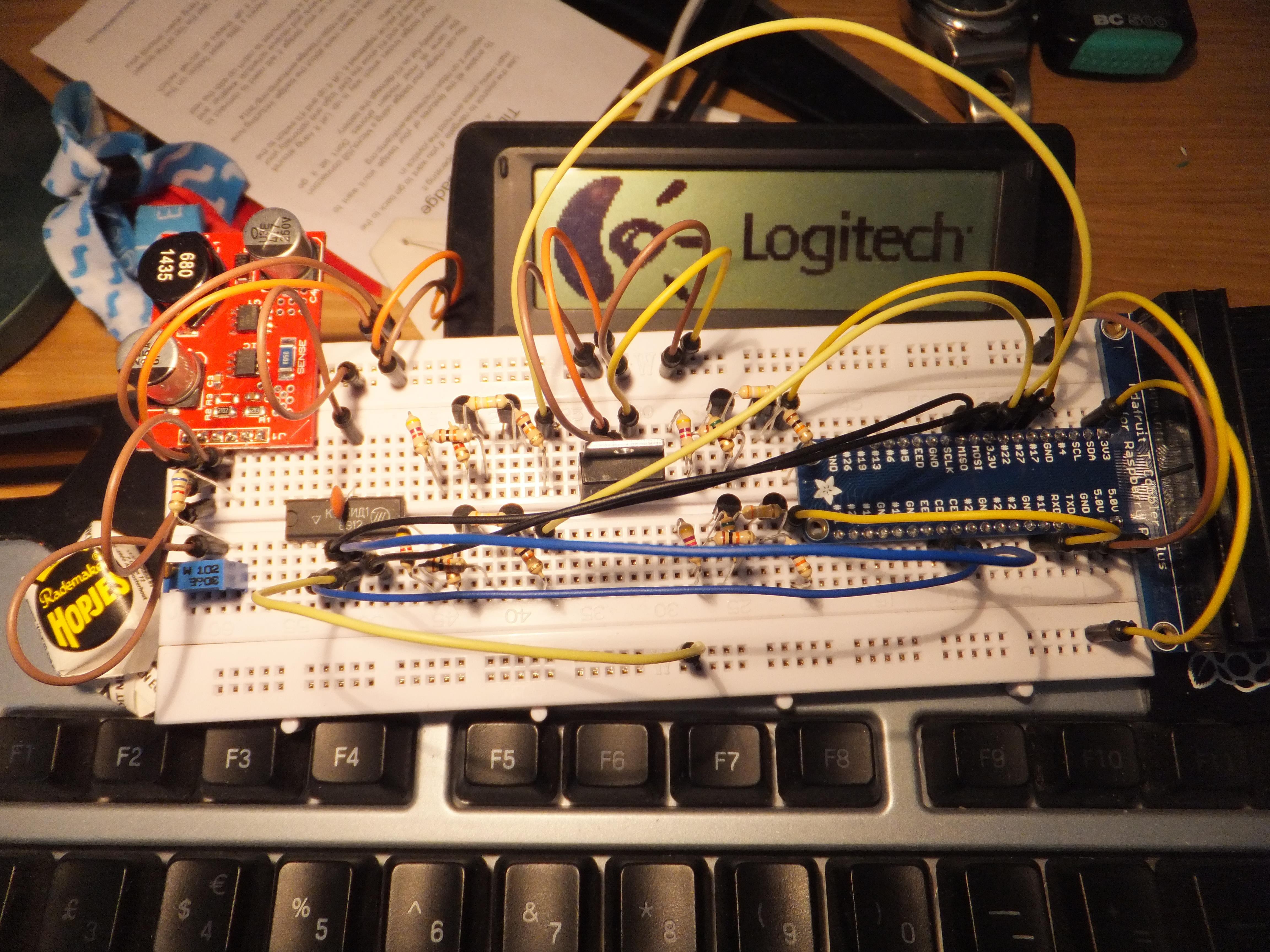
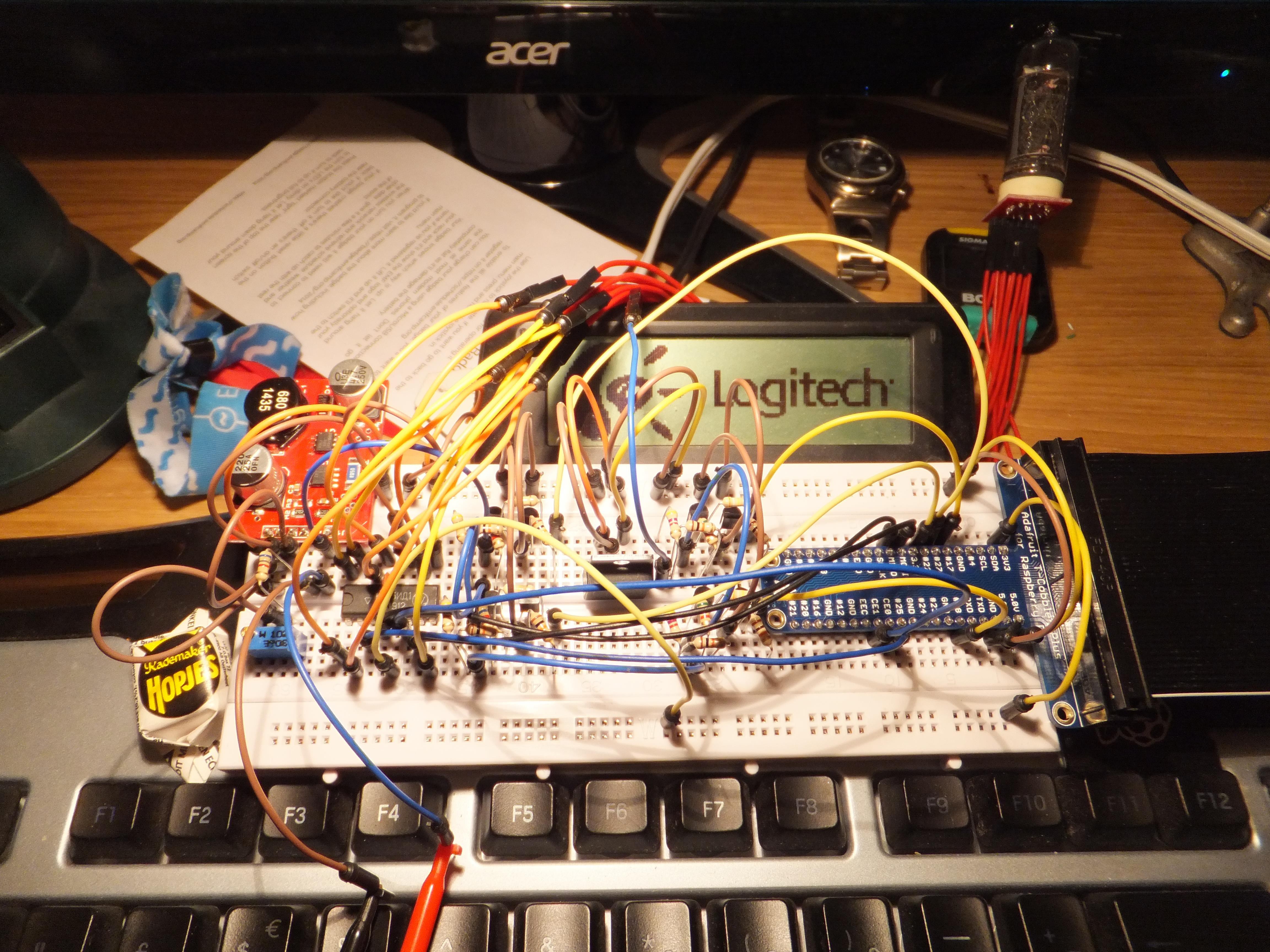
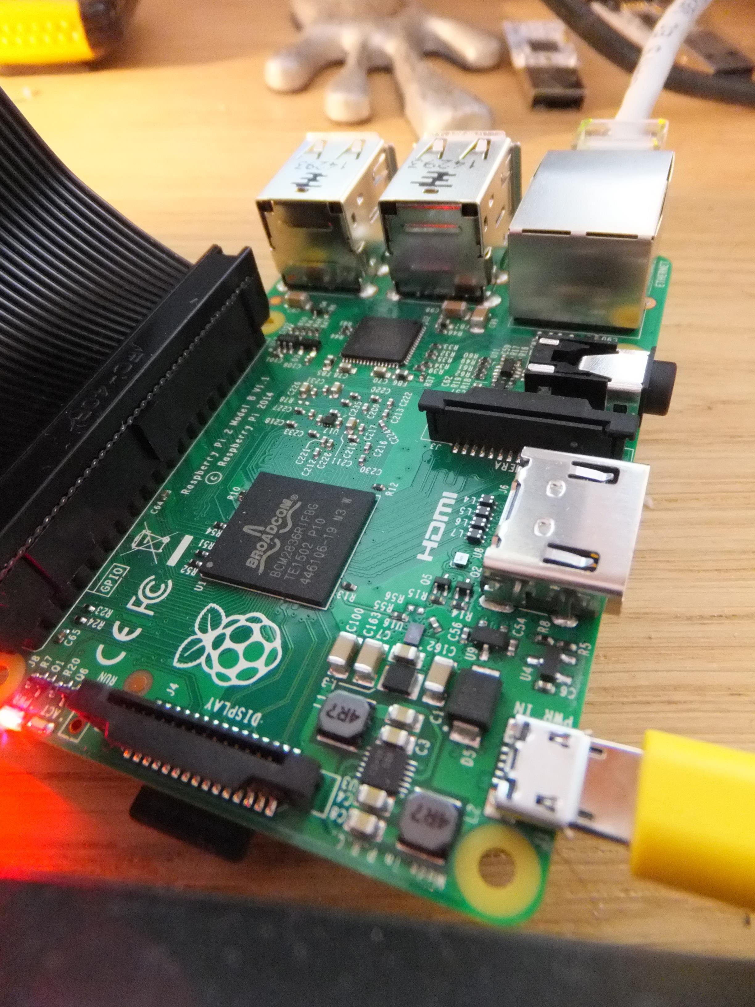
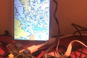
Use a combination of six Nixie tubes with a 16x2 LCD display and Pi2 with Adafruit Proto-Perma HAT to display information.
 Jon Davies "Woody"
Become a Hackaday.io member
Already have an account? Log in.
Just one more thing
To make the experience fit your profile, pick a username and tell us what interests you.
Pick an awesome username
hackaday.io/
Your profile's URL: hackaday.io/username. Max 25 alphanumeric characters.
Pick a few interests
Projects that share your interests
People that share your interests


 danielmcgraw
 James Fossey