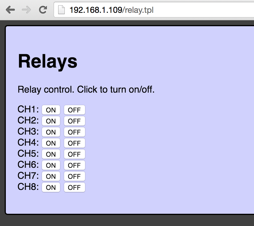
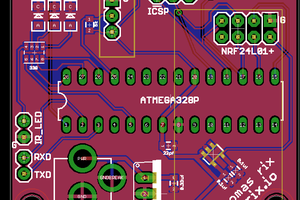
General Features & IOs:
- 8x Relay Channels - 10A 250V AC with NO/NC/COMMON connections
- PWR input (7-28V DC) with reverse power diode protection.
- Internal DC-DC module with 5V output
- RS232 level serial connection TX/RX/GND
- Reset Button
- Bootload/Program Button (GPIO0)
- User Input Button
- Status LEDs: Power, User Controlled (wifi activity), Serial TX, Serial RX


 Thomas R
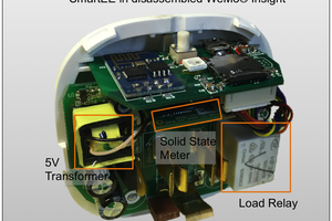
 John
John
 Alexander
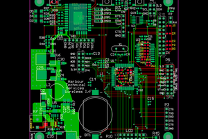
 Bharbour
Where can I find the instructions, code to make this