 Daniel Wiegert
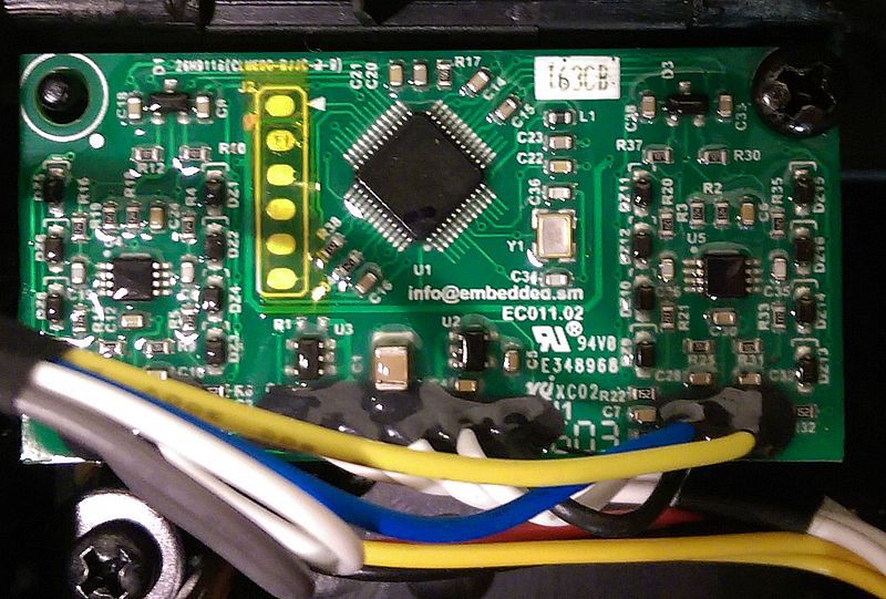
DB275 models uses a NXP LPC1768 arm Cortex-m3.
DB504 models are very similar to DB275 but uses a NXP LPC1788 arm cortex-m3.
DB297 models - please share images!
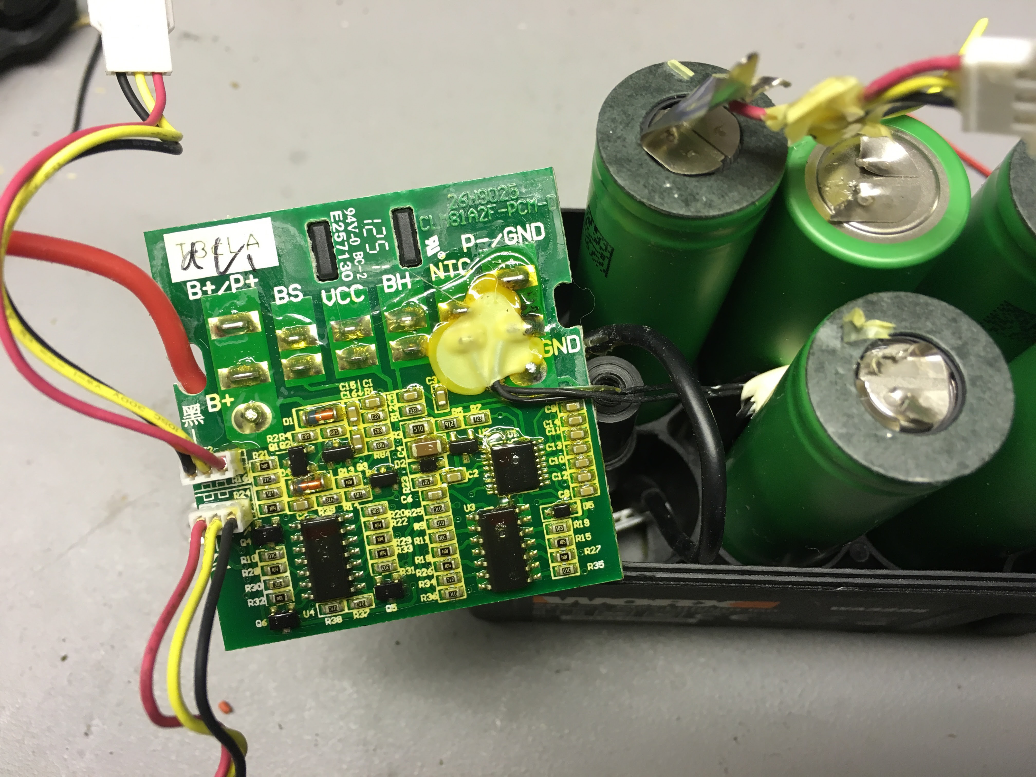
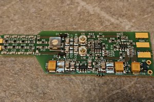
IC's on DB275-10:
- 3x3 FDD8424H 40V Dual N & P-Channel PowerTrench® MOSFET https://www.fairchildsemi.com/products/discretes/fets/mosfets/FDD8424H.html
- 3x MC33039 Closed Loop Brushless Motor Adapterhttp://www.onsemi.com/pub_link/Collateral/MC33039-D.PDF
- 3x mc33035dw Brushless DC Motor Controller http://www.onsemi.com/pub_link/Collateral/MC33035-D.PDF
- 2x unl2003a ULN200x, ULQ200x High-Voltage, High-Current Darlington Transistor Arrays http://www.ti.com/lit/ds/symlink/uln2003a.pdf
- 2x lm2904 Dual Operational Amplifiers http://www.ti.com/lit/ds/symlink/lm158.pdf
- 33063 MC3x063A 1.5-A Peak Boost/Buck/Inverting Switching Regulators http://www.ti.com/lit/ds/symlink/mc33063a.pdf
- lm238 THREE-TERMINAL 5-A ADJUSTABLE VOLTAGE REGULATORS
- lm239 Quad Differential Comparators http://www.ti.com/lit/ds/symlink/lm139.pdf
- 2x irf fr5305 http://www.irf.com/product-info/datasheets/data/irfr5305.pdf
- lm2904 Dual Operational Amplifiers http://www.ti.com/lit/ds/symlink/lm158.pdf
- cd4066bm CMOS QUAD BILATERAL SWITCH http://www.ti.com/lit/ds/symlink/cd4066b.pdf
- mic4680 1A 200khz superswitcher buck regulator http://www.micrel.com/_PDF/mic4680.pdf
- LIS352AR or similar 3-axis accelerometer http://www.farnell.com/datasheets/1698882.pdf chip has marking "327 35AR"
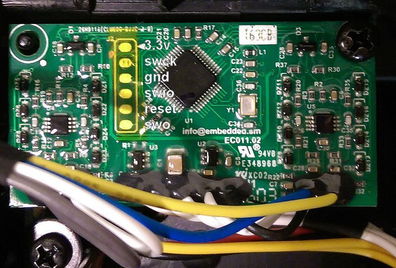
- LPC1768 Main cpu LPC1769/68/67/66/65/64/63 Product data sheet | LPC176x/5x User manual
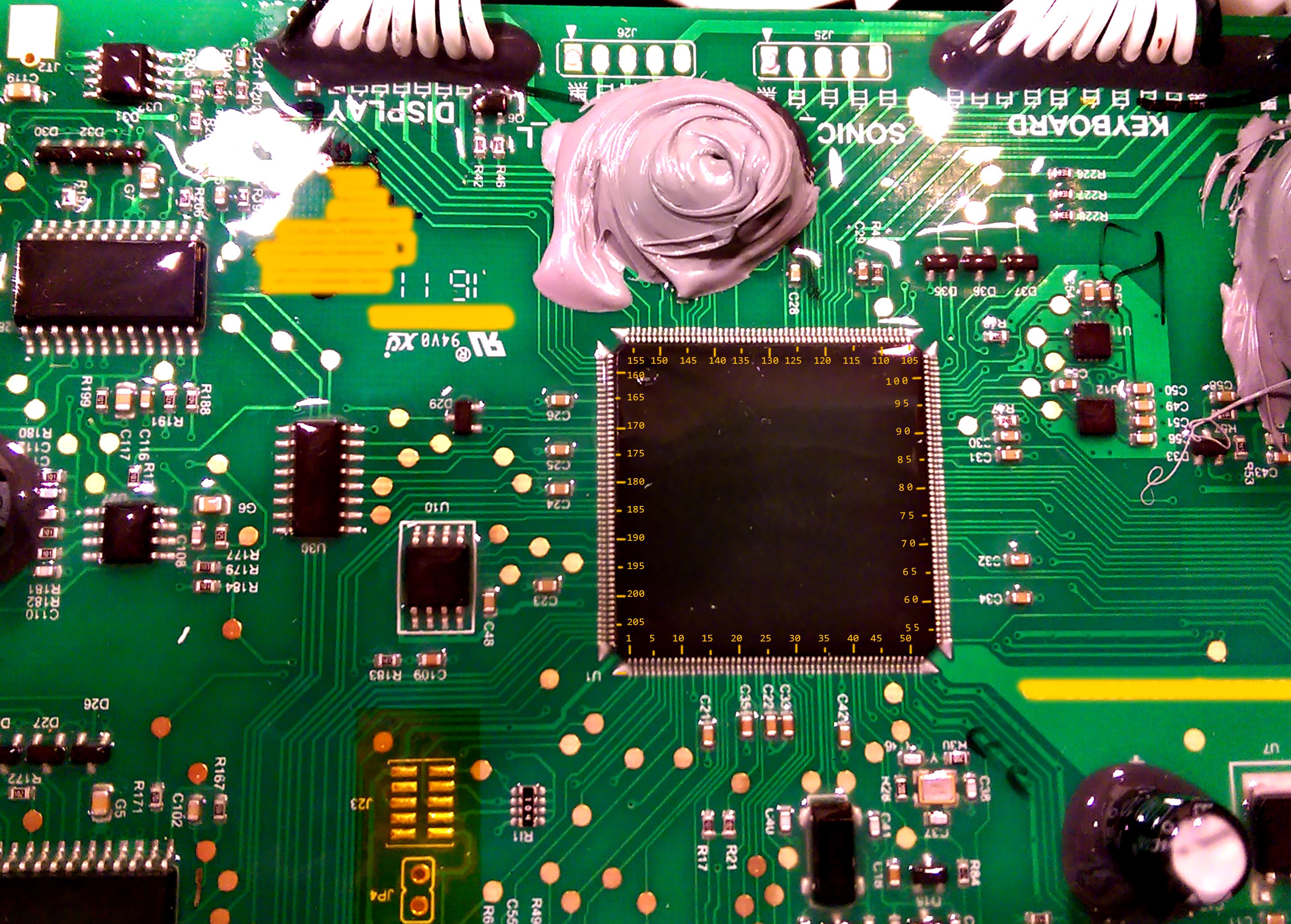
IC's on DB504-03:
- 3x3 FDD8424H 40V Dual N & P-Channel PowerTrench® MOSFET https://www.fairchildsemi.com/products/discretes/fets/mosfets/FDD8424H.html
- 3x MC33039 Closed Loop Brushless Motor Adapterhttp://www.onsemi.com/pub_link/Collateral/MC33039-D.PDF
- 3x mc33035dw Brushless DC Motor Controller http://www.onsemi.com/pub_link/Collateral/MC33035-D.PDF
- 3x unl2003a ULN200x, ULQ200x High-Voltage, High-Current Darlington Transistor Arrayshttp://www.ti.com/lit/ds/symlink/uln2003a.pdf
- 3x lm2904 Dual Operational Amplifiers http://www.ti.com/lit/ds/symlink/lm158.pdf
- 2x 33063 MC3x063A 1.5-A Peak Boost/Buck/Inverting Switching Regulators http://www.ti.com/lit/ds/symlink/mc33063a.pdf
- lm239 Quad Differential Comparators http://www.ti.com/lit/ds/symlink/lm139.pdf
- 3x irf fr5305 http://www.irf.com/product-info/datasheets/data/irfr5305.pdf
- 1x LD1086DT33TR 1.5 A low drop positive voltage regulator http://www.farnell.com/datasheets/1880971.pdf
- 1x TPD2E001DRSR Low-Capacitance 2-Channel ESD-Protection USB http://www.farnell.com/datasheets/2001596.pdf
- 1x AT25DF321 32-megabit 2.7-volt Minimum SPI flash https://www.sos.sk/productdata/76/10/0/76100/AT25DF321.pdf
- MMA8452Q, 3-axis, 12-bit/8-bit digital accelerometer http://www.nxp.com/files/sensors/doc/data_sheet/MMA8452Q.pdf
- ST L3GD20H, MEMS motion sensor: three-axis digital output gyroscope http://www.st.com/[..]/en.DM00060659.pdf
- LPC1788 Main Cpu LPC178x/7x Product data sheet | LPC178x/7x User manual
The onboard bootloader checks USB after memory stick after firmware file and flashes the its contents.
Custom firmware does not overwrite the bootloader, so it is possible to revert to original firmware.
DB275 firmware start at 0x9000
DB504 firmware start at 0x10000
Source code: https://github.com/Damme/LandLord
To setup build enviroment follow How to install the ARM toolchain
Also possible to use KEIL-MDK.
Please feel free to donate money.
I currently own thrr landdroid's. Two 791e 2015, 794e 2014 - with DB275 motherboard and one wg791e.1 (2016) with DB504.
Bitcoin: 3FnkdzXjkyeHK5o5H3wzM9jDzw52Q3GEog


 So far I've been developing and reversing DB275 (2015 WG790/791/794) It seams all 2016 has DB504.
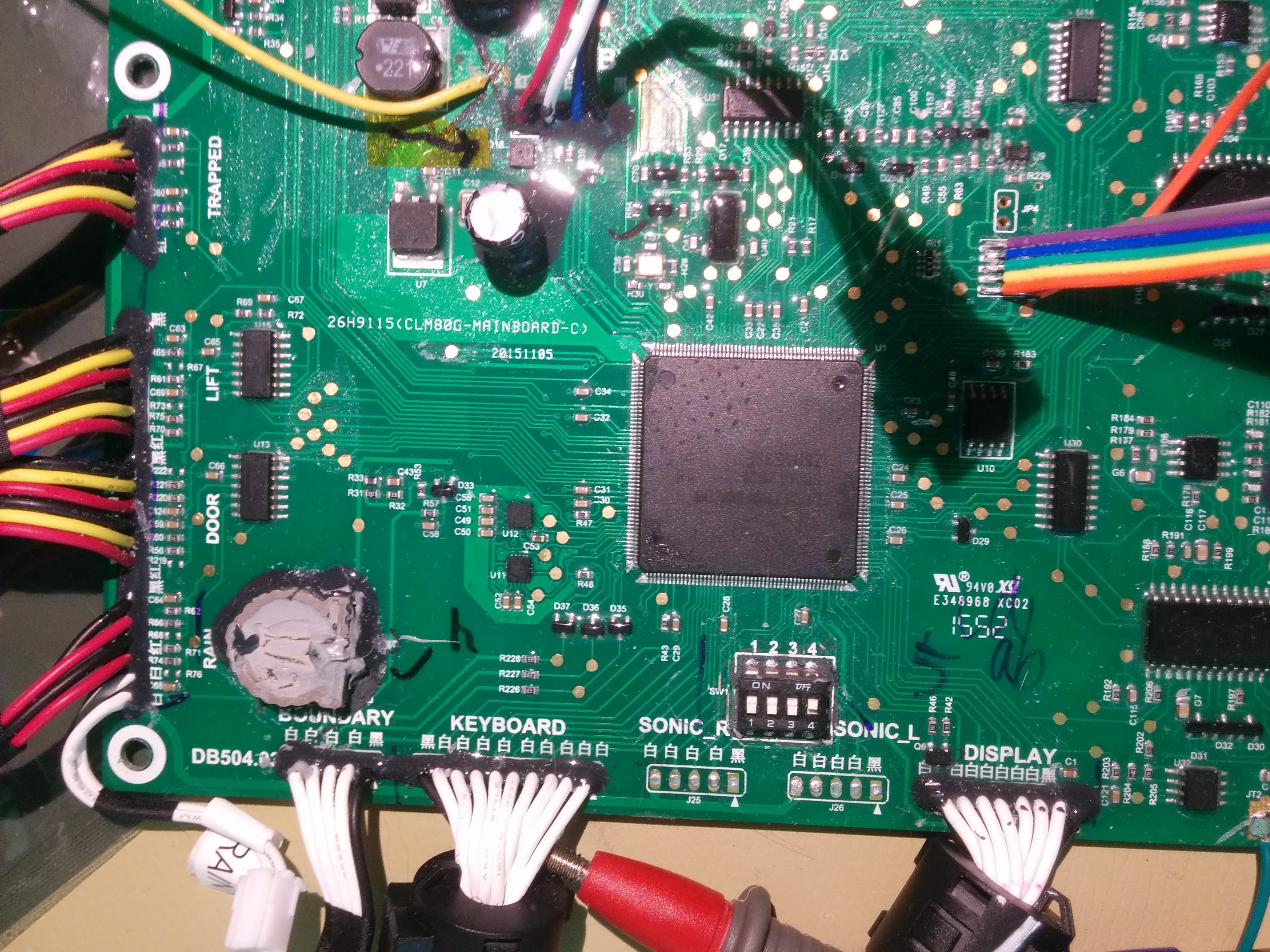


 Mastro Gippo
 Christoph
Hi. I was given a "broken" Landroid WG791E and thought maybe I could repair it and then hack it :-)
The first issue was that the power supply was soaked wet, having caused an internal shortcut. Using a separate PSU, I could get to the "base flashing green" state. I have access to the lawnmower's menu but the motors (wheels and blades) don't start, and I thought maybe that was because no boundary wire was detected nearby.
As I don't have the original boundary wire, I just plugged a piece of random wire between IN and OUT and the PSU overcurrent protection triggered immediately (over the stated max 1.5A) !
After putting a 1K resistor across the "boundary wire" connector, I measured a steady 28V DC on it, like it's directly connected to the incoming 28V, but that doesn't really make sense as the "boundary wire" seems to be just a wire with very low resistance, so I suspect the power part in the base is fried too, but it's hard to diagnose as it is fully potted...
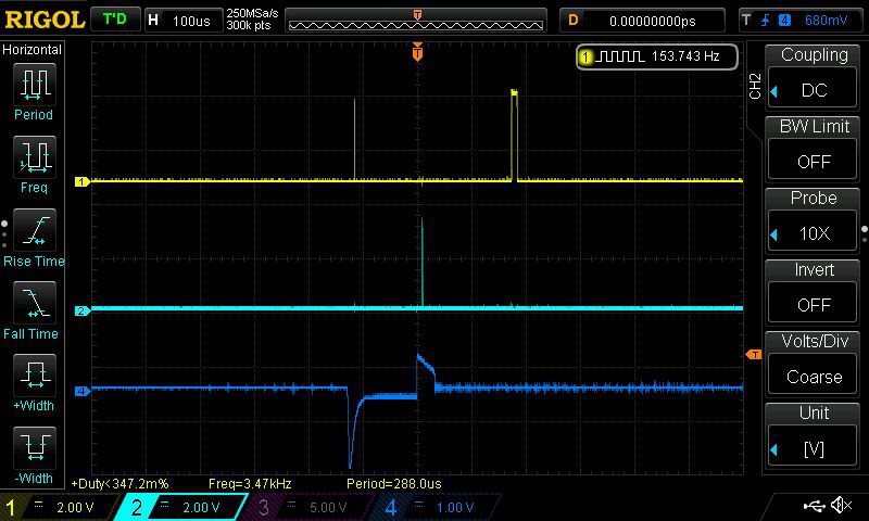
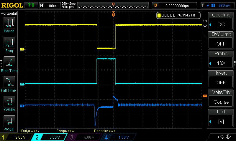
Do you have any information about what signal is required on the boundary wire (DC pulses or AC ? Voltage or current source ? Frequency ?)
Any information would be highly appreciated. KR. Vincent