My suspicions were correct. Display driver is TM1638 or similar. Shows mode selected and speed. Not sure what the 3 extra LEDs lit represent though.
I also found a settings menu.
Hold down button 1 for 5 seconds. Cycle through menu items with button 1. Change the setting with button 2/+ or 3/-. Finally hold down button 1 for 5 seconds to save.
F2 = (1-10) Ramping speed, fast (1) to slow (10). About 3 is a good balance. Too low a value and turning the motor speed up too fast can cause the controller to detect over current condition.
F3 = (1-80) Seems to affect the PWM's lowest duty cyle. About 10 is a good value.
F4 = (1-100) Push Button mode starting speed, as percentage.
F5 = (OFF/ON) Display set speed as percentage (OFF) or RPM (ON)
#P = (0-30000) Displayed speed in RPM at 100% speed
# Menu item only exists when F5 = ON
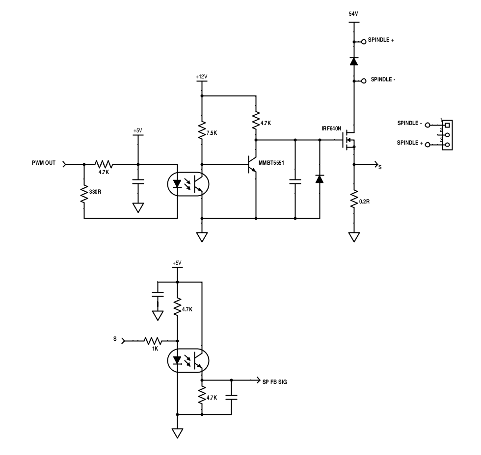
One annoying thing though, PWM mode will not to get up to 100% speed. Mine maxes out at 63%. As seen by the STC micro, 5V is 0%, 0V is 100%. Mine will get down to 2.5V. Not exactly sure what's causing this yet.
So I've worked out how to enable PWM on this controller and in the process discovered more features.
From what I can tell, there are three modes of speed control, trimpot/dial, +/- push buttons and PWM mode.
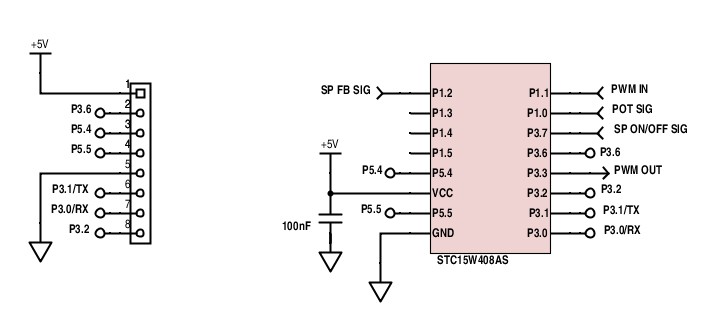
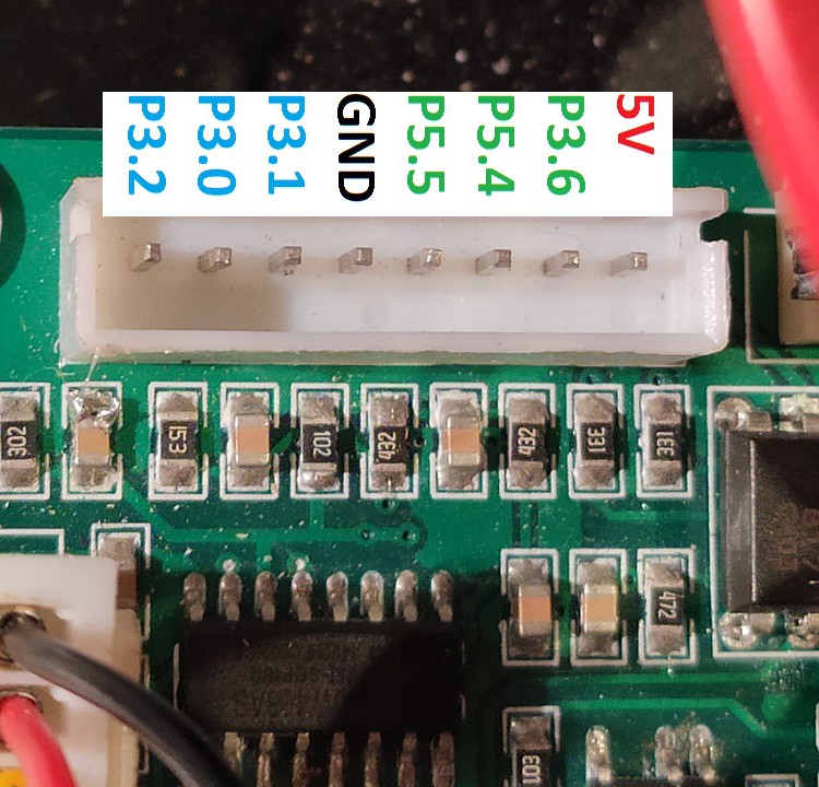
To enter into a mode connect momentarily either P3.0/P3.1/P3.2 to GND while spindle enable is off. P3.0 is dial, P3.1 is PWM and P3.2 is +/- buttons mode. Now enable the spindle and control the speed. To control the speed in +/- buttons mode, P3.0 is + and P3.2 is -.
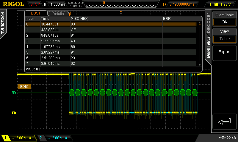
P3.6, P5.4 and P5.5 are serial pins that go to a seven segment driver IC, looks to be TM1638. P3.6 is CLK, P5.4 is DIO and P5.5 is STB. From what I've decoded on my oscilloscope, the display says which mode you are in, current state of the spindle (on/off) and the spindle set speed represented as a percentage. Data in the image below is reversed, should have been LSB. 0xC0, 0x73, 0x89, 0xC2, 0x06, 0x89, 0xC4, 0x40... If the TM1638 is used, more buttons might be available.
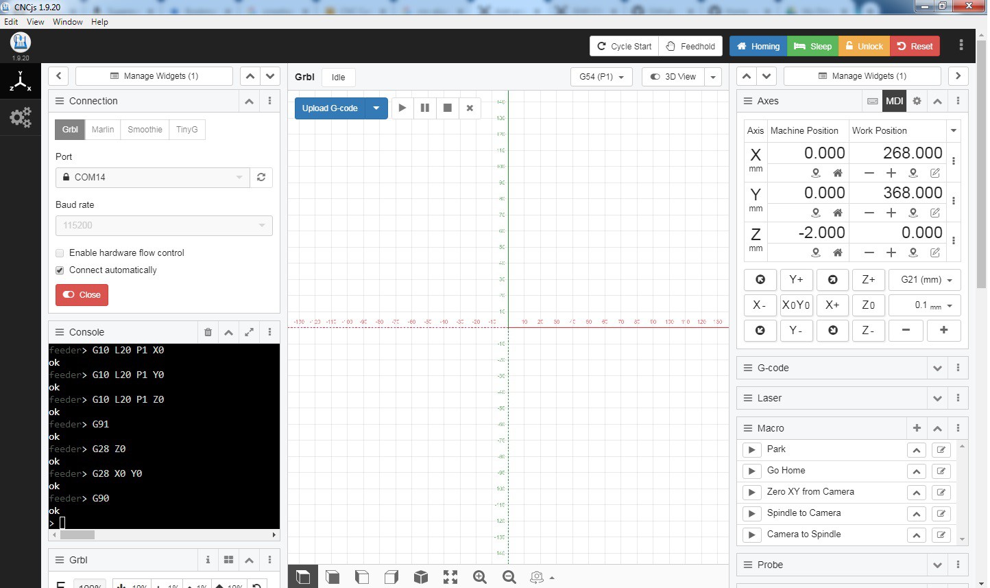
I've got PWM to work through Pin 17 of the parallel port, but mind you, the signal from GRBL needs to be inverted first, otherwise for example g-codes S1 would be flat-out and S11000 off.
Here's how it's connected...
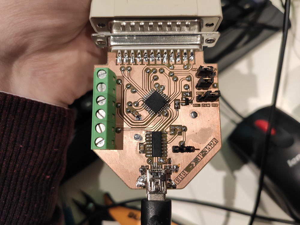
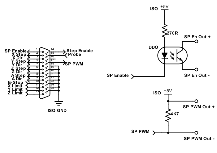
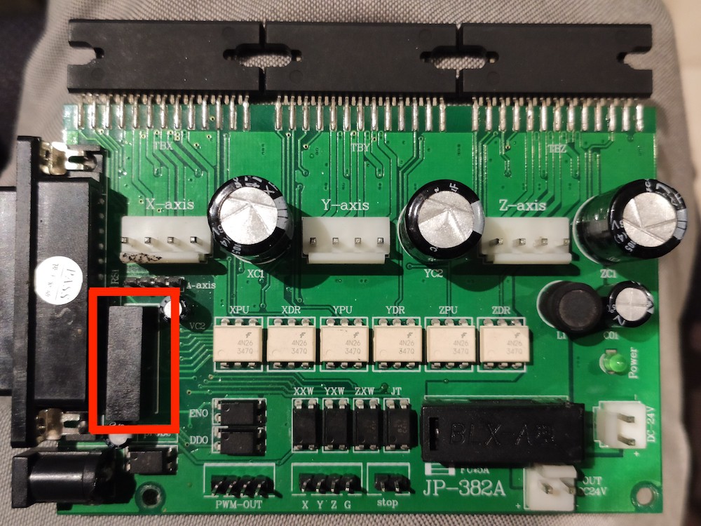
Signal into Stepper Controller (JP-382A) via DB25 and circuit pre four pin connector:
If you're curious, the ISO +5V is a isolated 5V generated on the stepper controller by this unmarked black box:
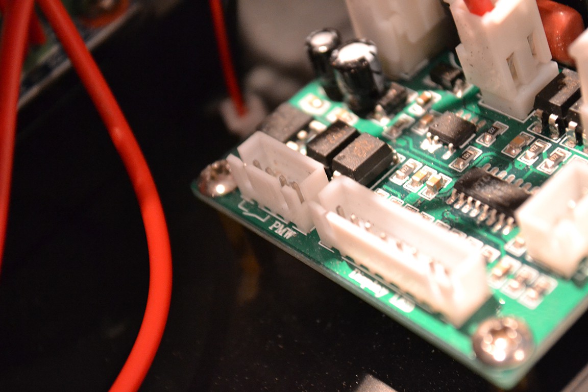
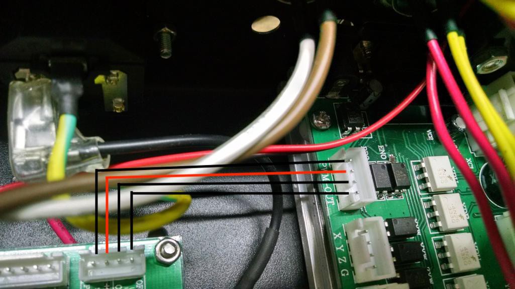
Four pins on the Stepper Controller connector labeled PWM-OUT go to another four pins on the Spindle Controller connector labeled PWM:
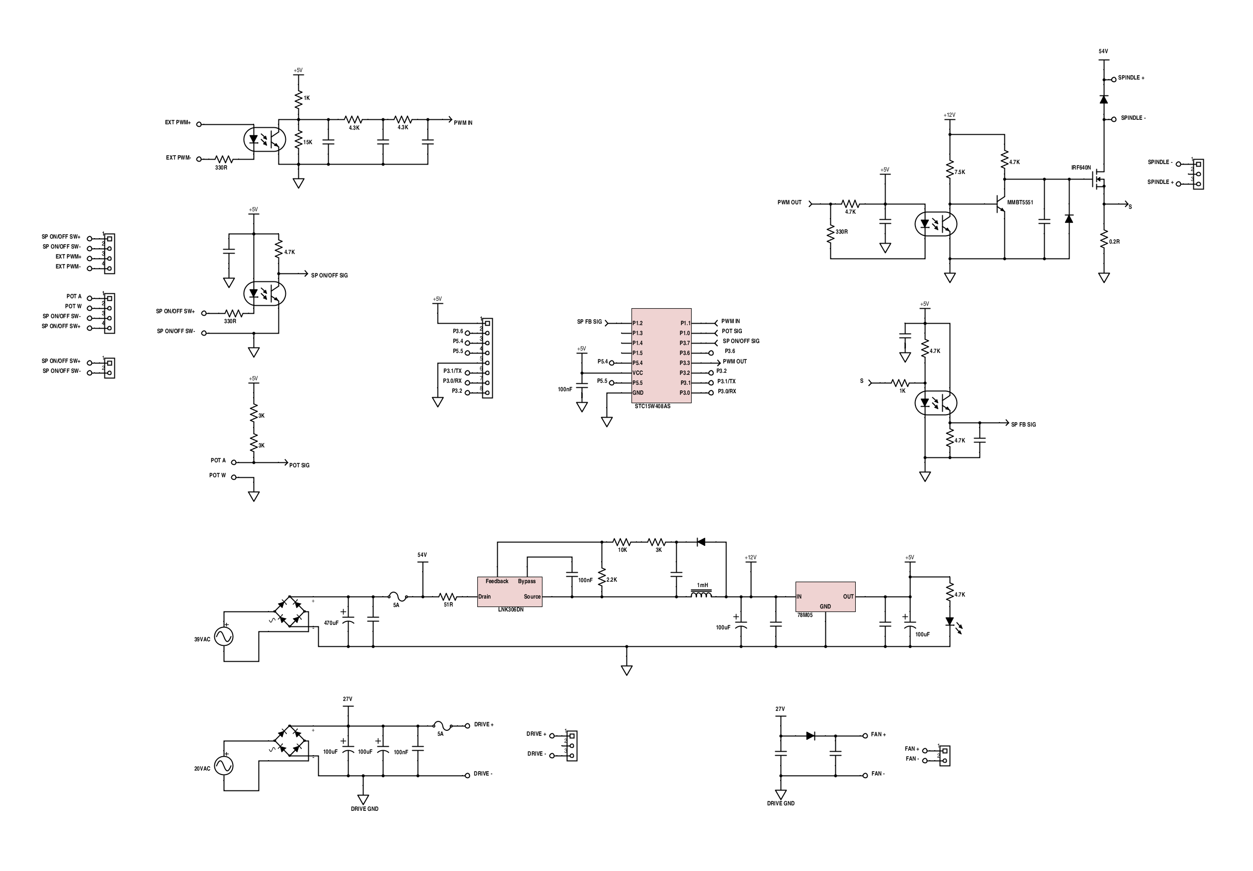
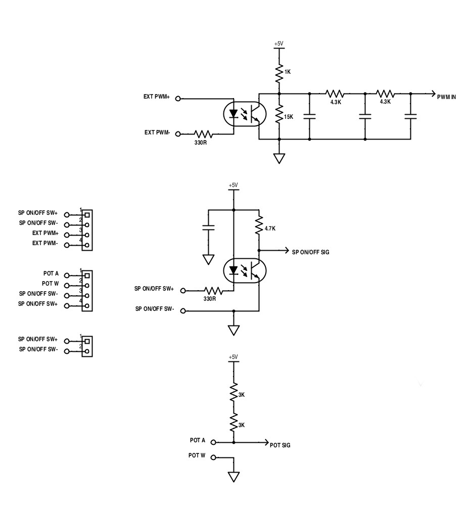
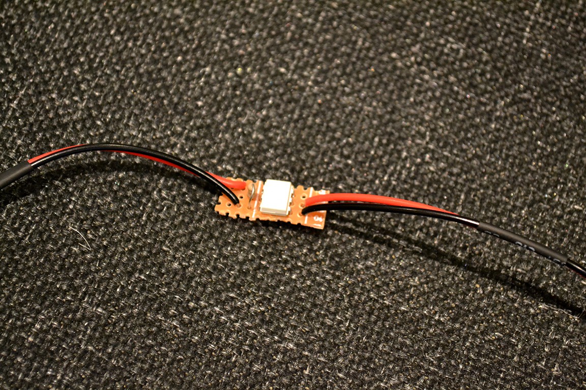
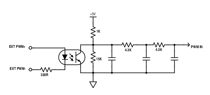
The image below is the PWM in circuit on the Spindle Controller.
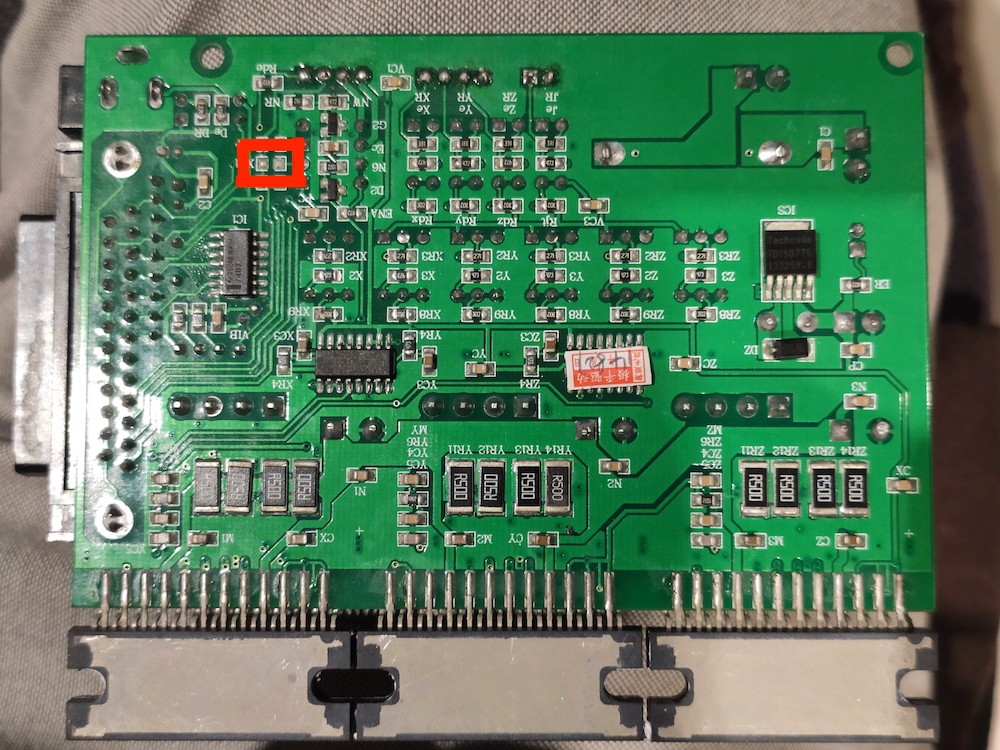
Also a side note. The Stepper Enable signal from the DB25 Connector does nothing due to a missing resistor on the LED side of the optocoupler. The Enable on the stepper drivers are permanently on.
So I never got round to getting software speed control working, just didn't need it and couldn't be bothered, manual control works fine for what I do...
Recently I started working on my Nixie Clock project again and I needed to mill a wooden enclosure. So I dusted off the CNC and had a go. The TinyG somehow changed its G54 during a big job, and ruined the work. This happened several times more. I looked on Synthetos's github for an update for the TinyG v8, but there hasn't been one for 4 years! Seems they only work on the TinyG G2 these days. So I decided it was time to let the TinyG go...
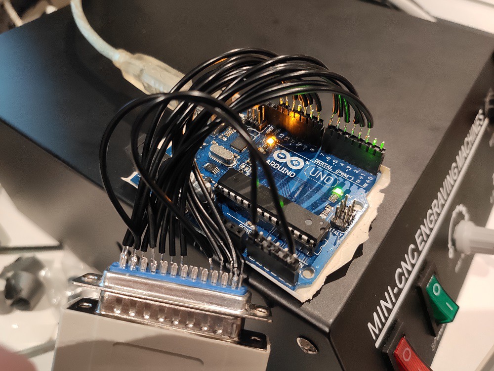
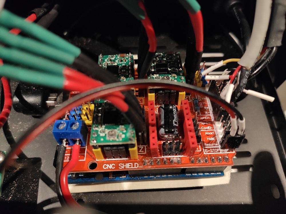
At work we use a X-Carve which runs on GRBL. I've never had an issue with GRBL, so I swapped out the TinyG for GRBL. I placed Arduino Uno with CNC Shield found on ebay. And was very pleased with the results.
I then discovered the ESP32 port of GRBL and wanted to try that, but didn't want to rewire everything again just to try out new controllers. So I put the original stepper controller back in and tested GRBL plugged in via the parallel port.
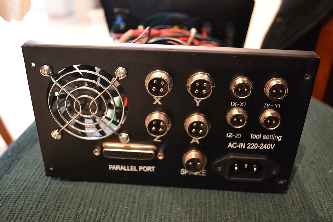
Some reverse engineering of the parallel port was required. Here's what I found:
(as seen from back of female connector)
PIN 1 - Spindle Enable
PIN 2 - X Step
PIN 3 - X Direction
PIN 4 - Y Step
PIN 5 - Y Direction
PIN 6 - Z Step
PIN 7 - Z Direction
PIN 8 - A Step
PIN 9 - A Direction
PIN 10 - E-Stop
PIN 11 - X Limit
PIN 12 - Y Limit
PIN 13 - Z Limit
PIN 14 - Step Enable (all axis) (does nothing, see later log)
PIN 15 - Probe
PIN 16 - ?
PIN 17 - Spindle PWM
PIN 18-25 - Ground.
All are active low.
Works great!
I needed to slightly modify GRBL's config.h:
Un-comment INVERT_SPINDLE_ENABLE_PIN and USE_SPINDLE_DIR_AS_ENABLE_PIN.
Note Spindle Dir pin is on D13 pin on arduino and this will toggle with the bootloader LED flashing at startup. This means your spindle will inadvertently turn on and off a few times if you are in dial mode with the dial left at full lol. To avoid this, remove the bootloader and download the grbl firmware straight to flash.
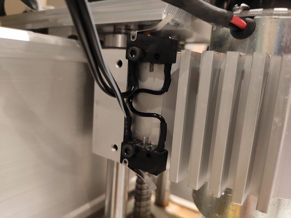
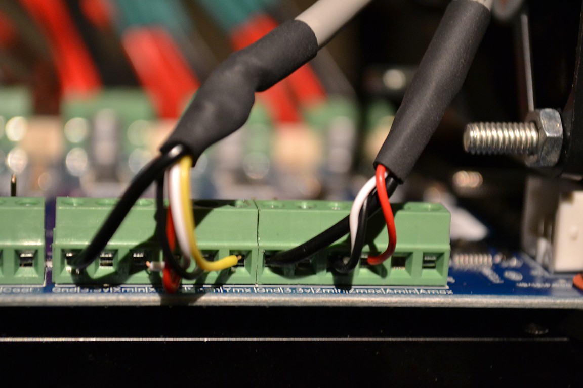
GRBL and the original stepper controller only has one limit switch input per axis, so I've had to rewire the limit switches in series (because I'm using NC switches).
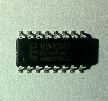
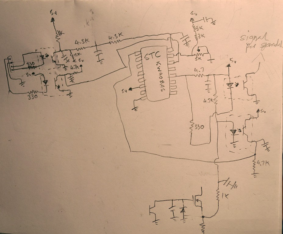
I've found the datasheet for the mysterious STC15W408AS microcontroller on the spindle controller board. Turns out it's a 8051 at heart. The datasheet is well documented and is surprisingly in well written english. The device is super easy to program too, only need a USB to UART adapter, Keil C51 compiler, uVision4, and a STC ISP application. Hopefully I can read the program memory and save it as a backup. This may be the neater solution. Just program the micro to have the PWM feature. I'll do more reverse engineering and have a play I think.
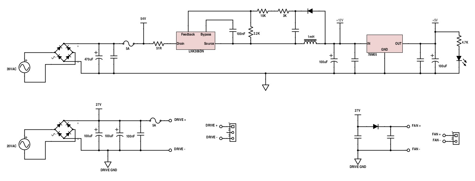
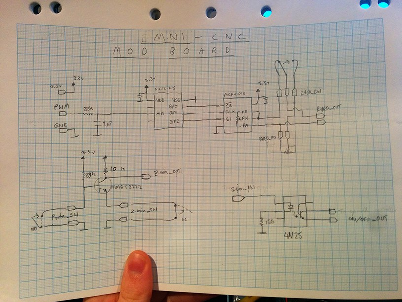
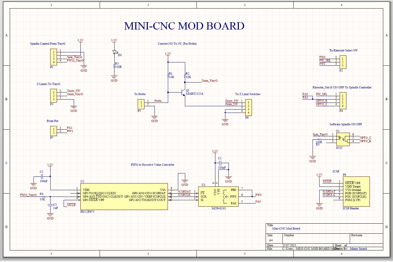
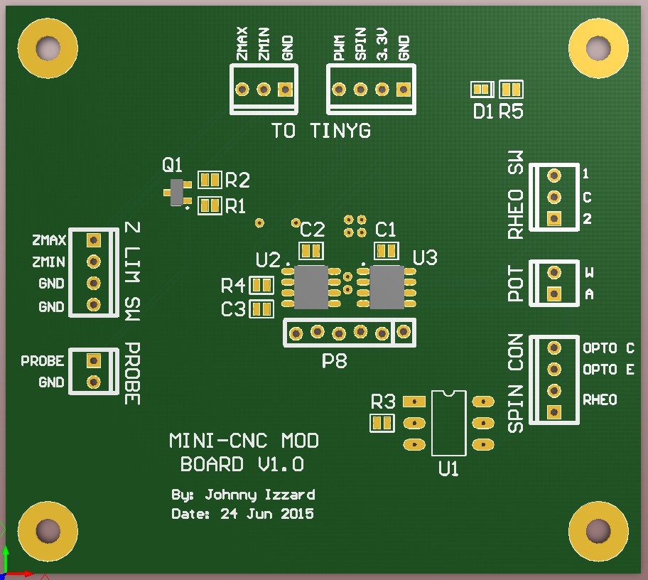
So, I started working on designing a board to achieve spindle speed control in software, and also be able to turn it on/off. The spindle speed control works by passing the PWM through a low pass filter, then reading the DC voltage produced on an analog pin of a PIC micro. The micro then reads the value (most significant 7-bit's of 10 bits), and sends it to a digital pot. The digital pot contains an 8-bit data register (16-bit really with command byte) and is 10K and we need 5K, so that's why we are grabbing 7 bits (need 8 bits and grabbing 7-bits divides the value in half). The last log explains why I need to convert PWM to a resistive value (voltage divider). I've also added a feature for the Z auto level probe on the board. The issue there is, my system has been configured to work with Normally Closed limit switches and the act of probing, is a Normally Open operation. So I've made a little circuit to make probing mimic a NC switch. Some parts should arrive this week. I can then make sure it's working 100% before sending the gerber files to seeed studio.
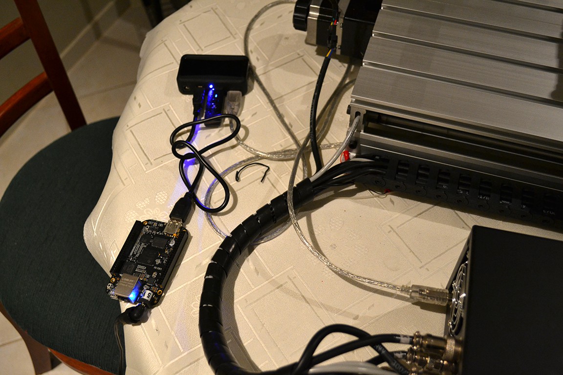
Added beaglebone black with wifi dongle and now it's wireless. All I needed to do was set the beaglebone black to start the serial port json server and wifi at startup. All that's required is plugging in the power and a way we go.
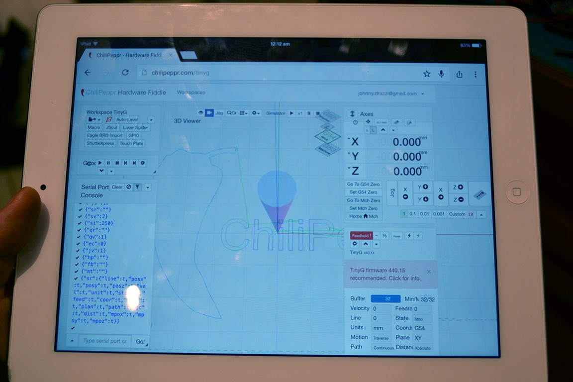
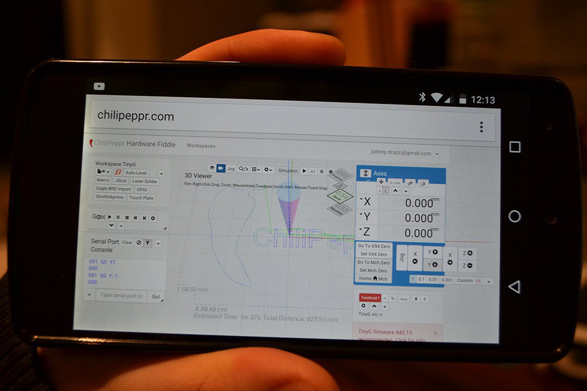
Thanks to Chilipeppr being so portable (it's browser based). I can even control the CNC from an ipad or smartphone.
Lastly I made the spindle able to be turned on and off in software with M3 and M5 commands.
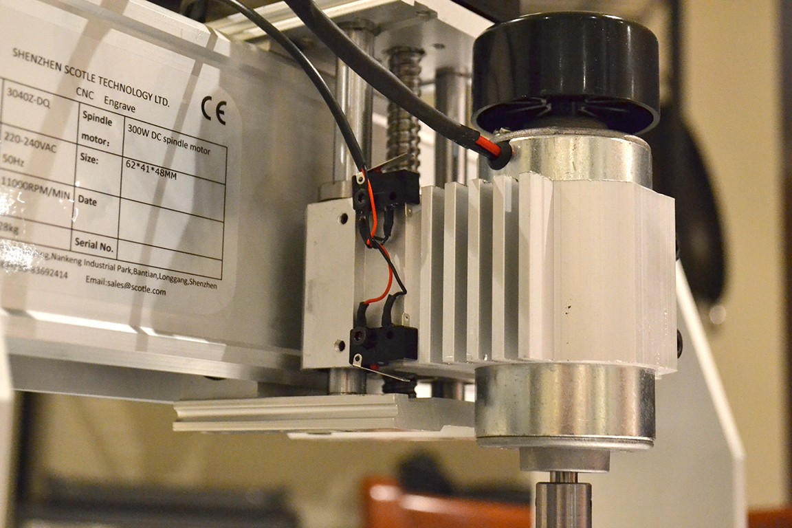
I tried getting the external PWM spindle control going, but it seems the microcontroller on the spindle controller board has not been configured for it (on this model) :(. The PWM sent to the motor is controlled by this micro by looking at a voltage divider's voltage, who's value changes via the 5K front pot (used as rheostat). From what I can see, the divider is 6K to 5v and 5K rheostat (pot) to ground. The external PWM pin on the board looks to goes through a lowpass filter and to an analog pin on the micro. Despite the different frequencies and duty cycles I tried on the PWM pin, I can't get it to work. I'm thinking of adding a small PIC that can read the PWM signal from the TinyG and control a digital potentiometer (as rheostat). I might add a small switch on the from of the case to select which pot to use (software or manual control). Not elegant, but will work fine.
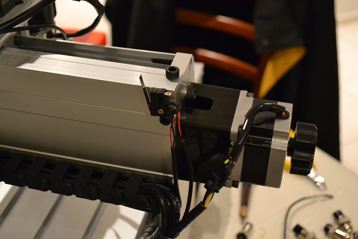
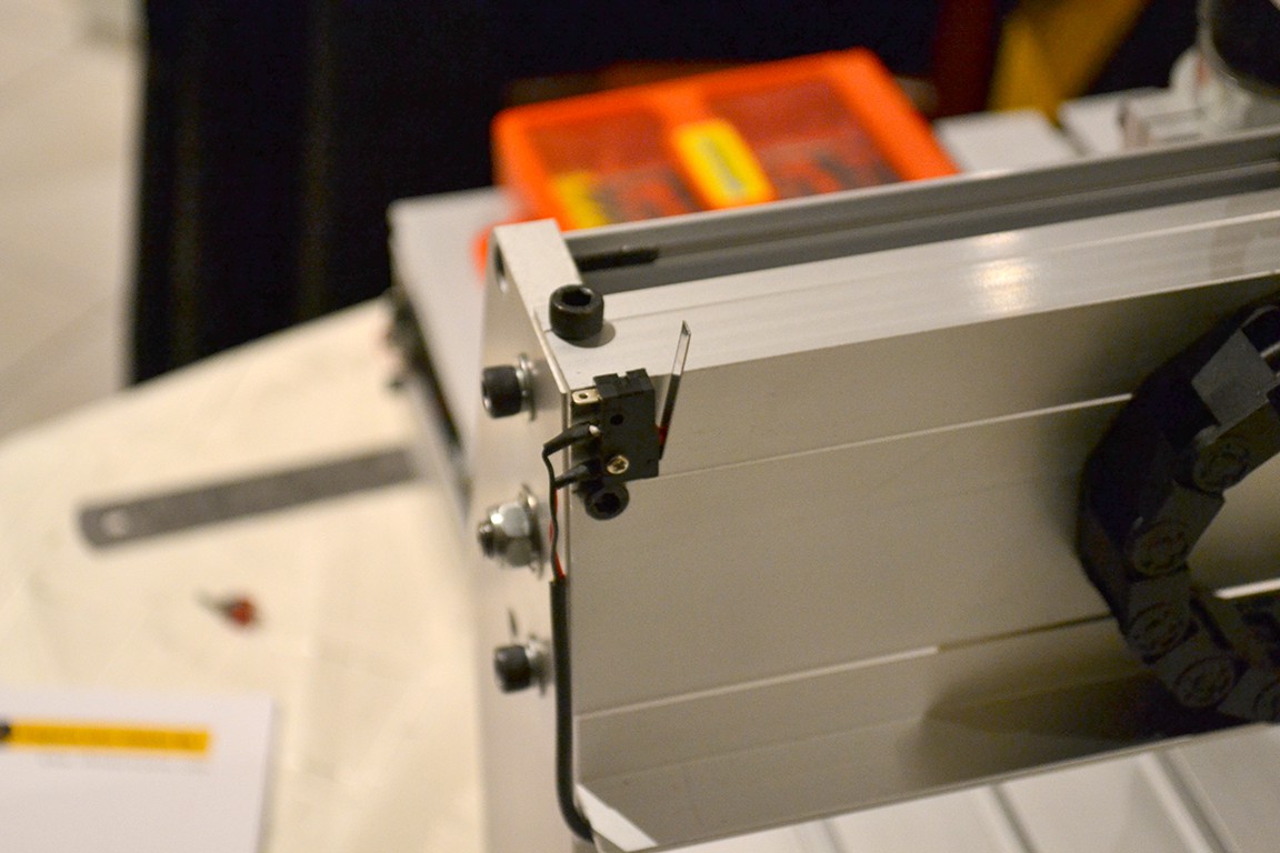
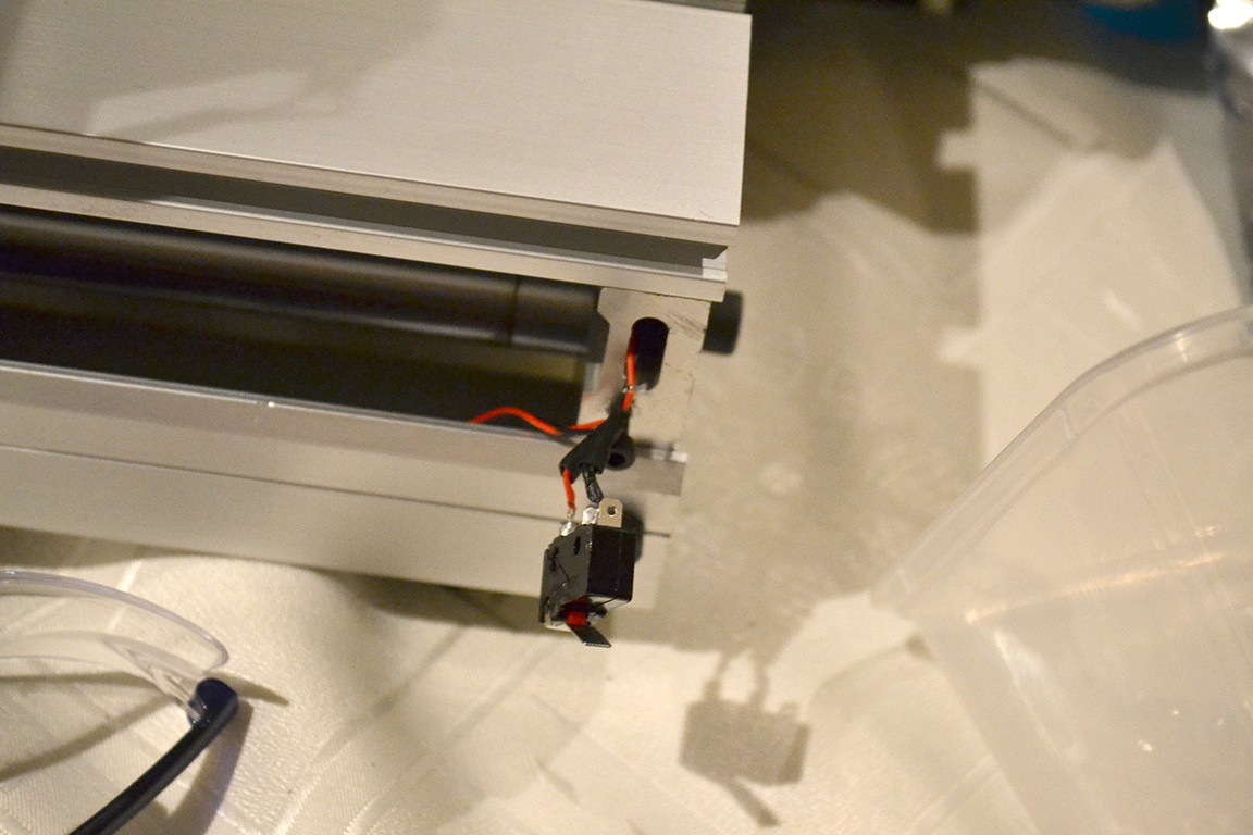
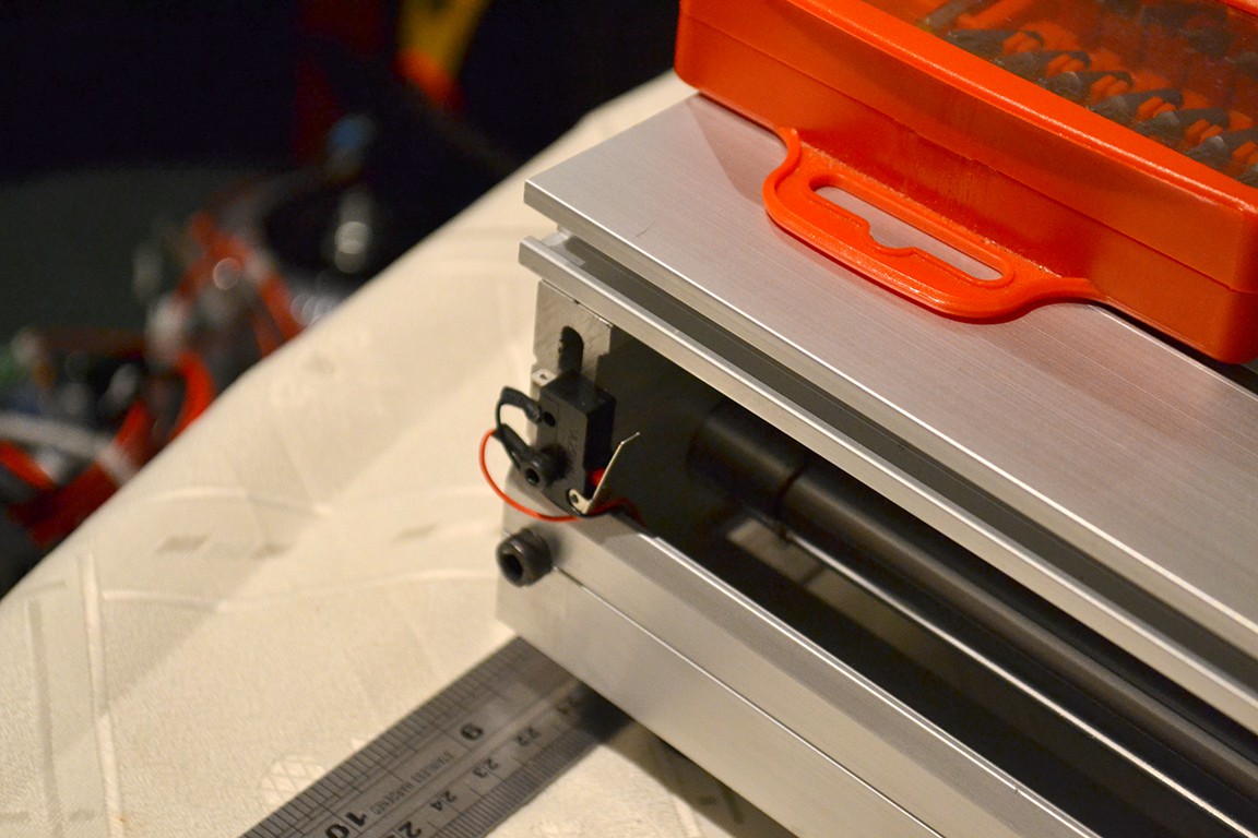
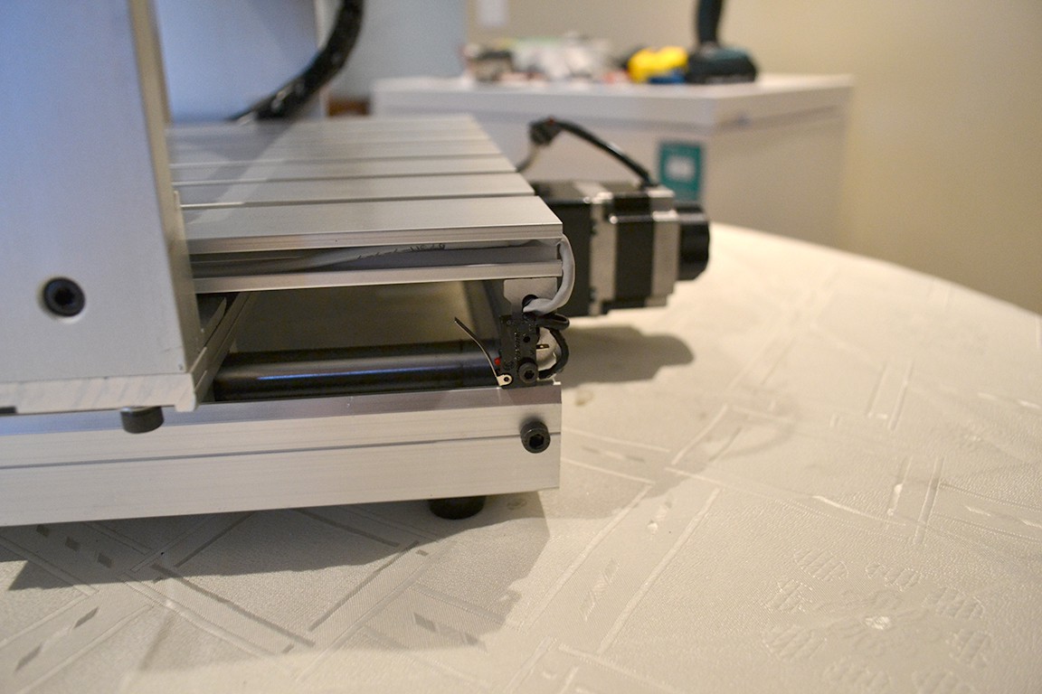
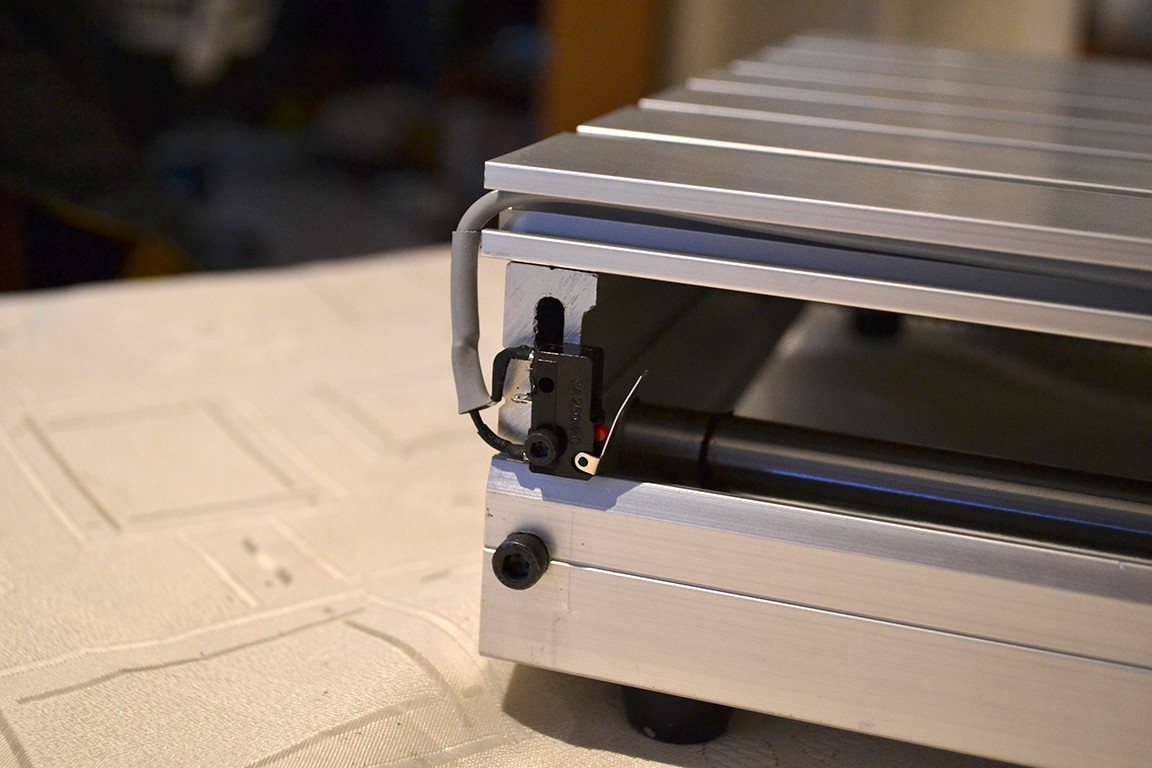
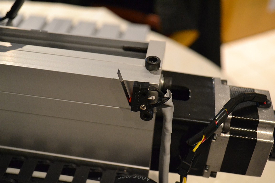
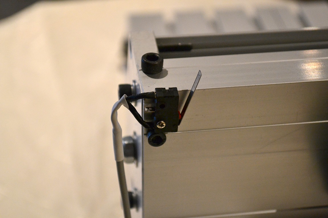
And here are the new ones. Notice now that I am using the limit switches as Normally-Closed. This is for better noise immunity and extra safety. Using NC switches has the added benefit that the machine will know if a wire comes loose on a limit switch.
I also spent most of the day working out how to software control the spindle speed. The spindle controller board has pins for this (PWM) but not clear details on the function of the pins.
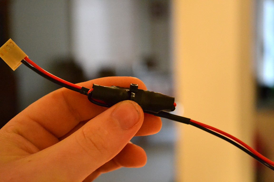
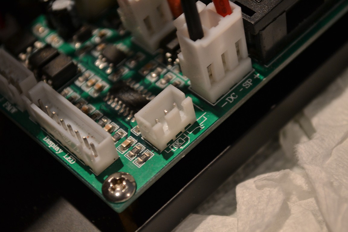
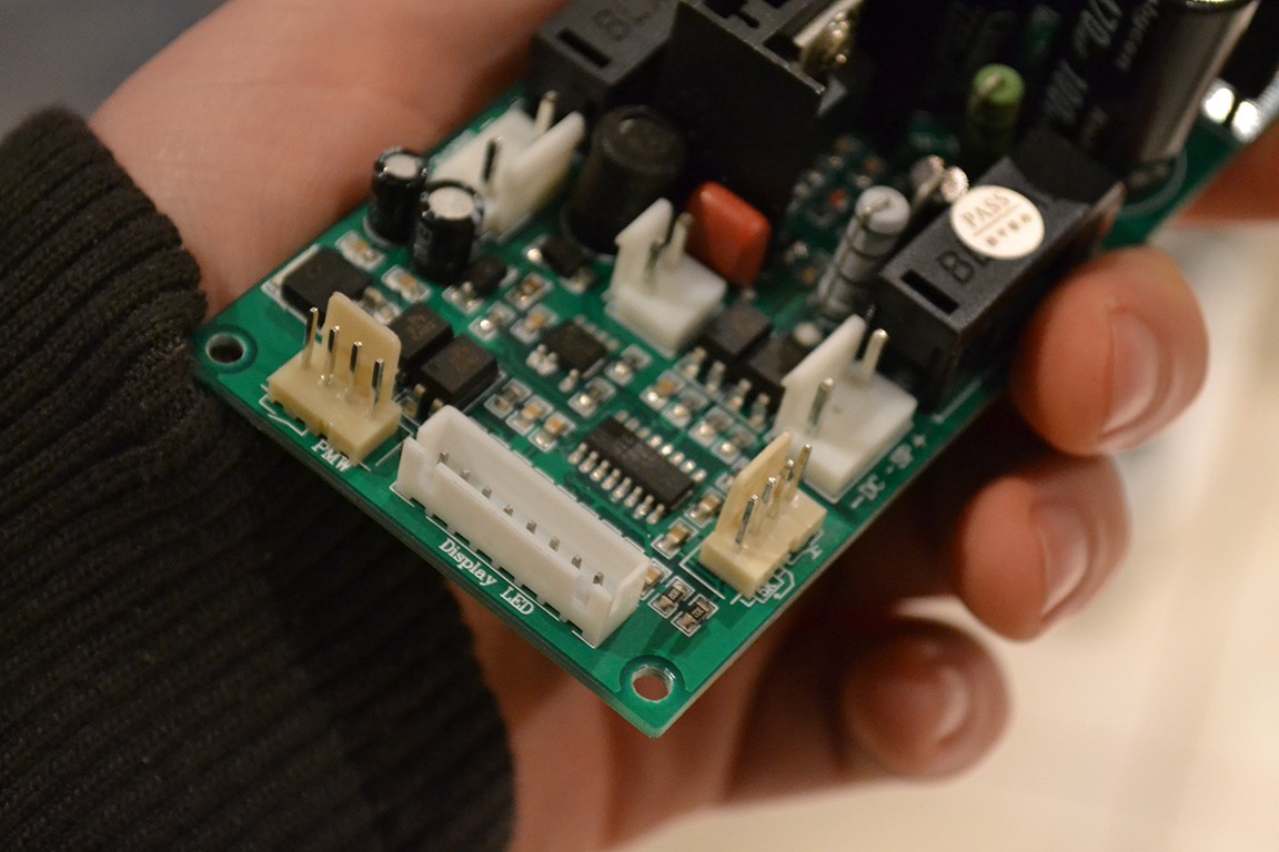
I first replaced the connectors to ones I can work with.
I did some quick reverse engineering of the spindle controller and hope to try this out at a later time.
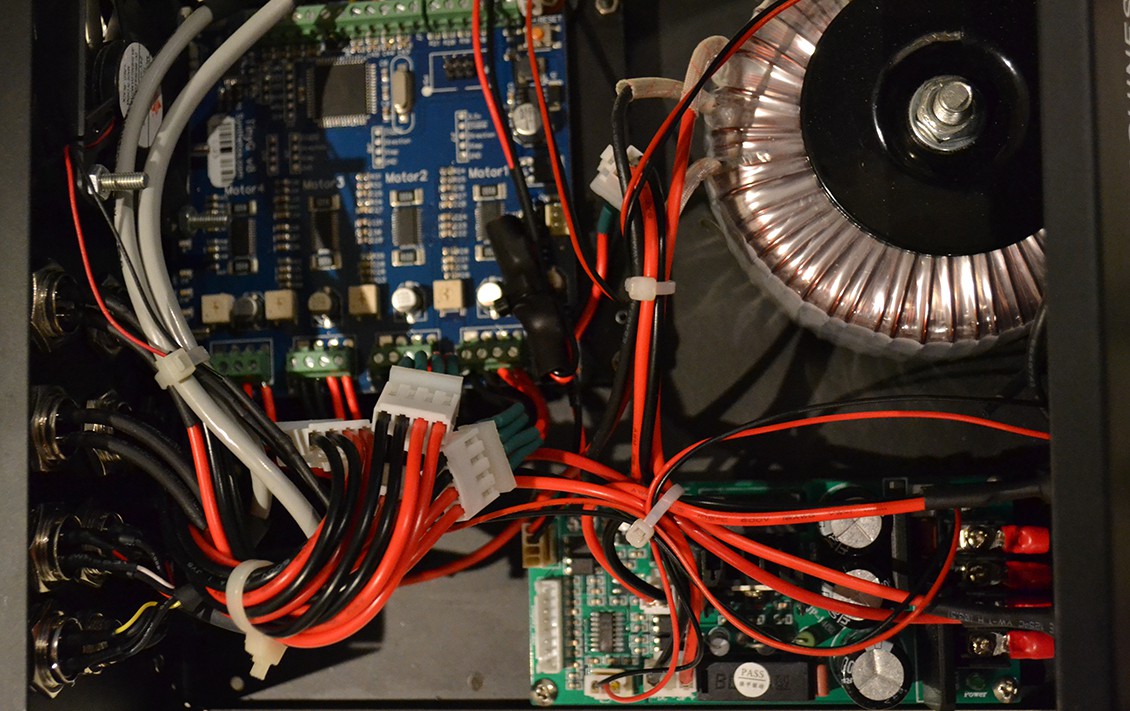
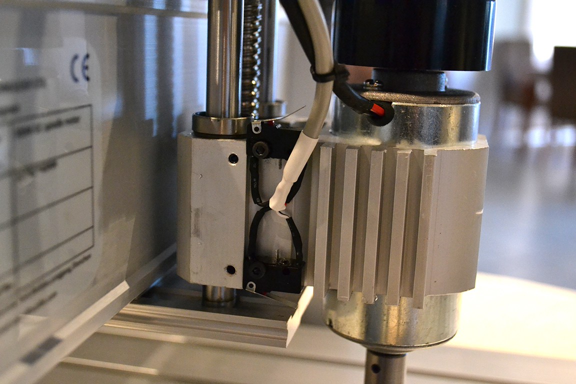
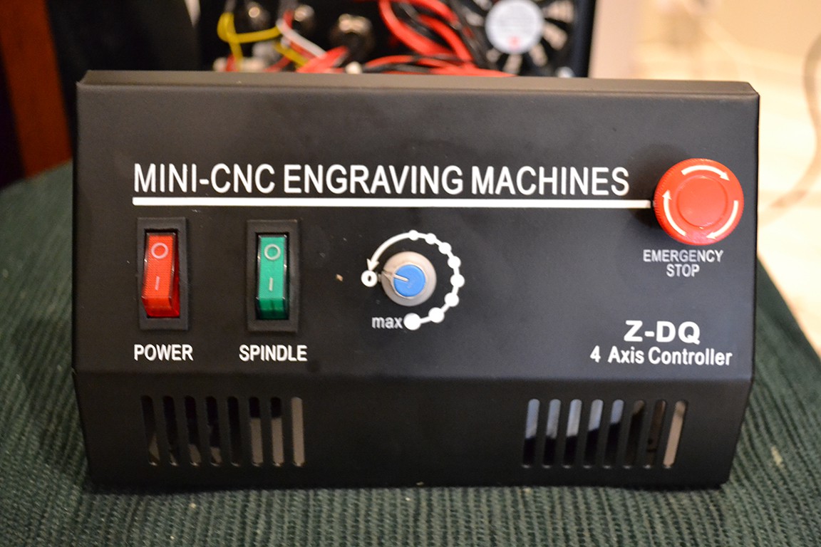
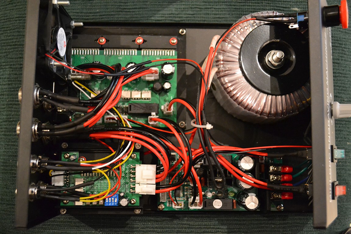
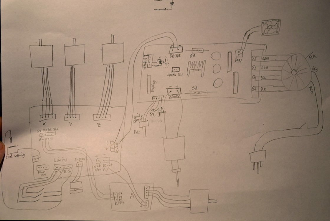
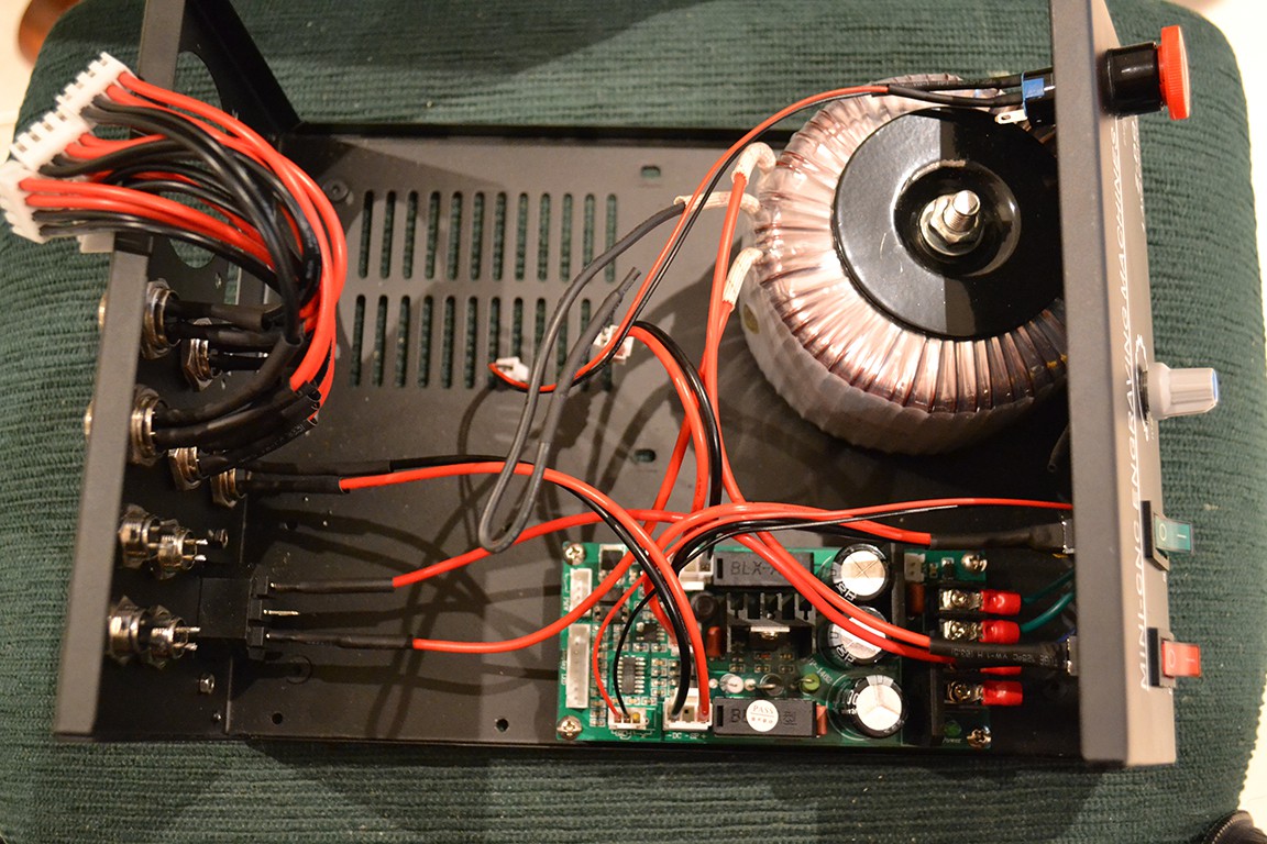
The first thing I did was inspect the existing controller and tried to get an understanding of the existing system.
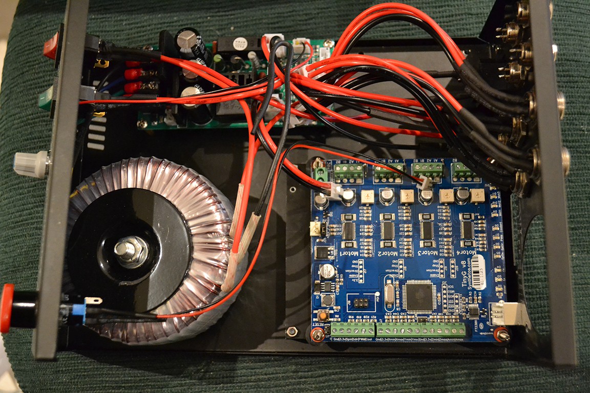
As you can see, the controller has three PCB boards inside. A 3 axis stepper controller (JP-382A), 4th axis controller (JP-1635A), and combined power supply and spindle controller (JP-1482). The controller box also has limit switches for x, y and z. Unfortunately they are wired in parallel, so the TinyG would not know the different between hitting the min or max limit on different axes (useful for homing).
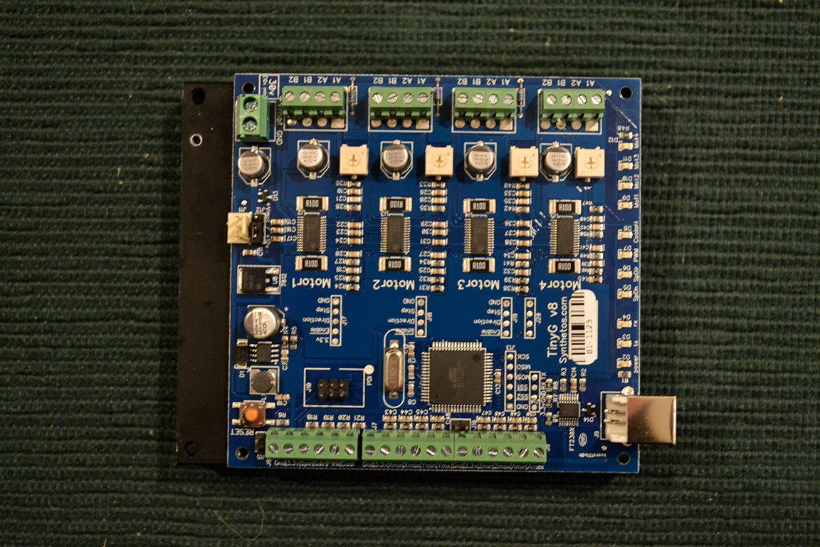
Next I removed the fan, and stepper controllers.
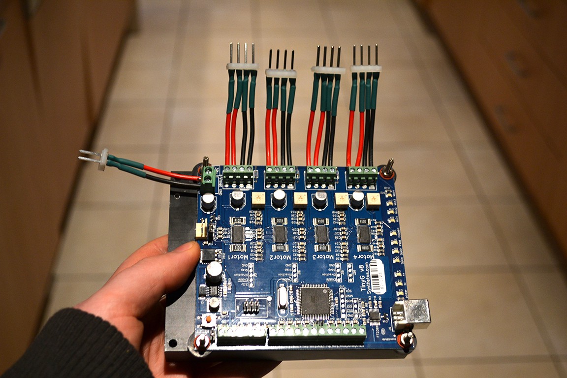
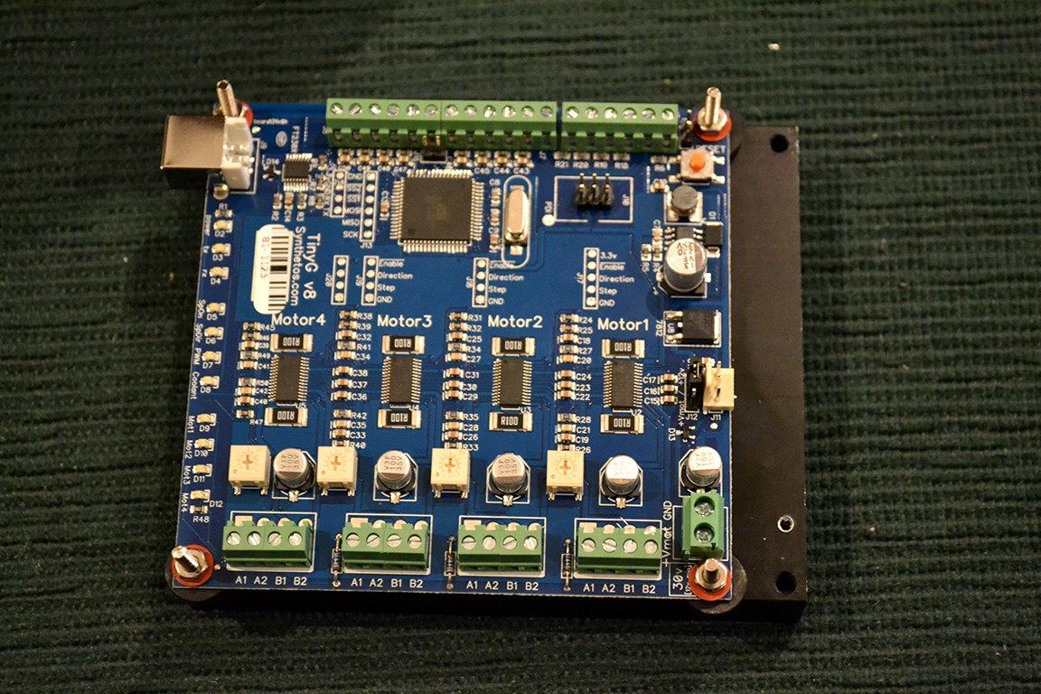
I lined up the TinyG against the old heatsink and 3 holes lined up out of 4. Not bad.
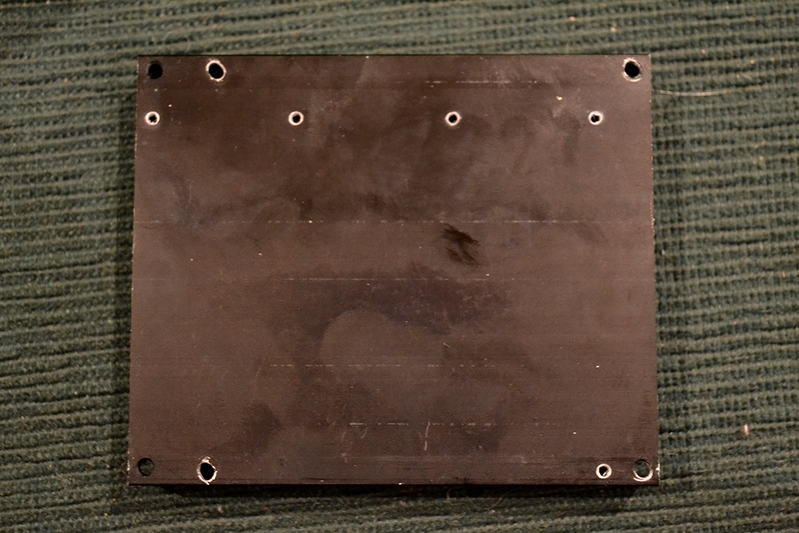
I drilled out the 4th hole and widened the holes just a bit for a better fit.
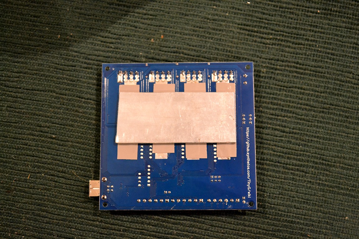
I cut a piece of aluminum to connect the TinyG's heatsink pads to the old heatsink with thermal tape.
Here is the final result. Notice I used M3 bolts with plastic spacers.
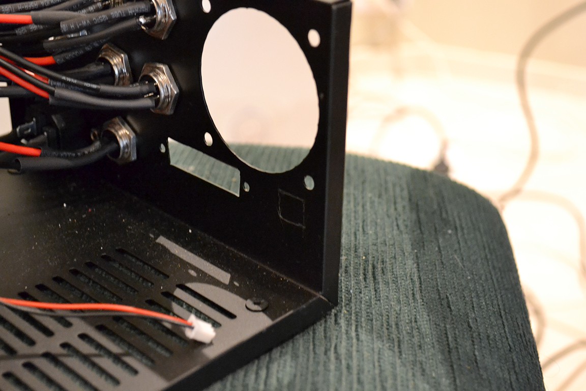
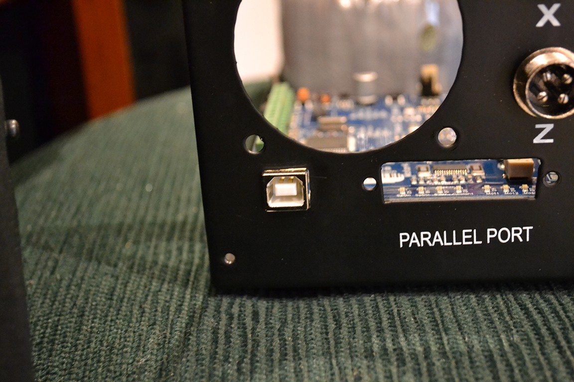
Next I marked where the USB will poke out the back, drilled a hole and filed the hole square.
Here's the result.
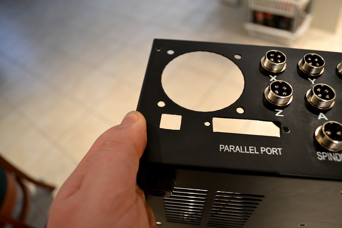
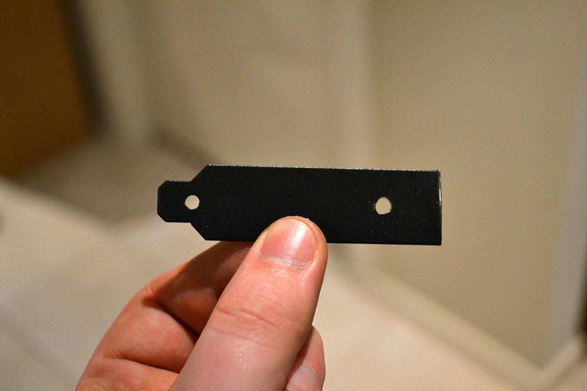
Next I made a cover for the parallel port hole using a blank PCI-e slot cover.
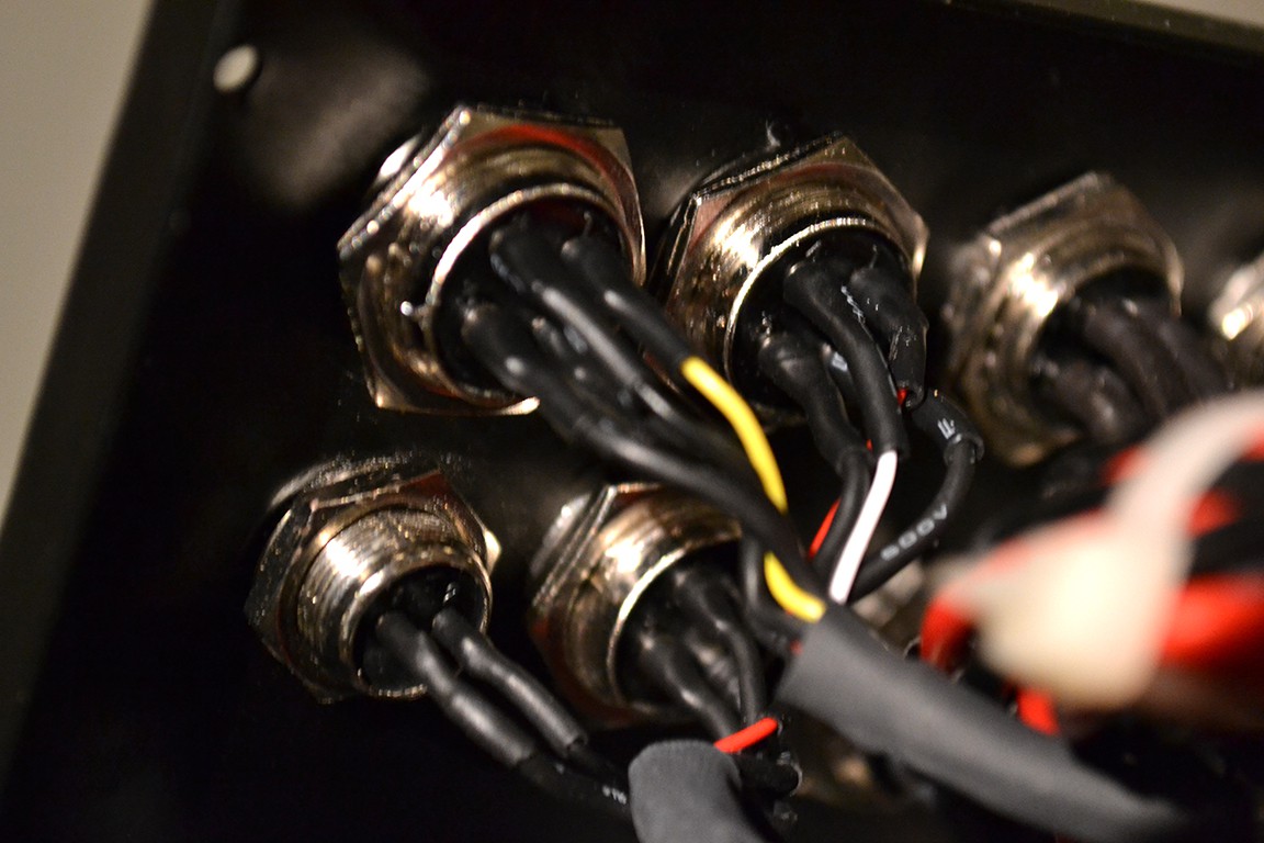
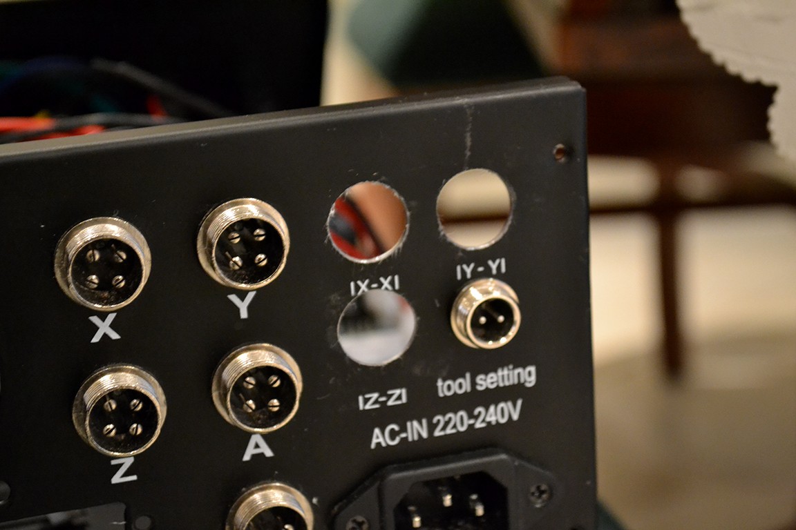
The next step was creating larger holes to fit 4 way aviation connectors to accommodate for new limit switch setup. That is, limit switches for min and max. To do this is used my Proxxon tool (like a dremel).
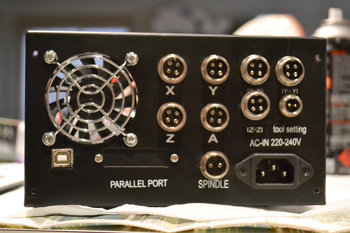
Finally I put some anti-rust paint on the cut surfaces (because this enclosure is steal and will get cancer) and installed the new connectors.
 Johnny
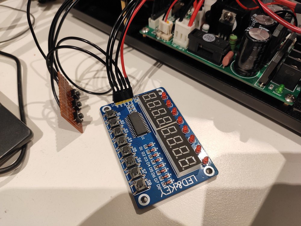
 I then discovered the ESP32 port of GRBL and wanted to try that, but didn't want to rewire everything again just to try out new controllers. So I put the original stepper controller back in and tested GRBL plugged in via the parallel port.
 (as seen from back of female connector)