Close
0%
0%

Outback MATE Reverse Engineering

Reverse engineering Outback Power's Solar Chargers so I can obtain better data for logging

Similar projects worth following
Outback Inc. sell a family of solar chargers and inverters which communicate via a proprietary bus. They intend you to use their "MATE" controller which spits out some fairly basic ASCII log data, but it's missing a lot of data, and wouldn't it be nice if I could just do away with the MATE altogether and talk to the solar charger directly?

This project documents my reverse-engineering process into figuring out how to talk directly to an Outback MX solar charger, and possibly also the Outback FX inverter and FlexNET DC monitor devices.

Using what I discovered, I developed a small python library that can run on a light-weight linux device and pretend to be a MATE controller. This allows me to collect statistics and upload them to my server, providing very detailed insights into the health of the system!

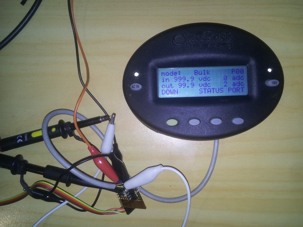
We have a holiday house with a complete off-the-grid solar charging system, which consists of 6 solar panels and a 24V / 525Ah battery bank. The Outback MX solar charger we use has a special port that you can connect an Outback MATE to, which itself has an RS232 port for logging data.

However this logging data is a pretty basic ASCII packet, and I was frustrated that I couldn't access the more advanced information shown on the LCD! So I started this project in an attempt to access the raw data myself.

The result is pyMATE - an open-source python library that can speak the native protocol that Outback devices use, and it opens up many more possibilities than the RS232 port alone could provide.

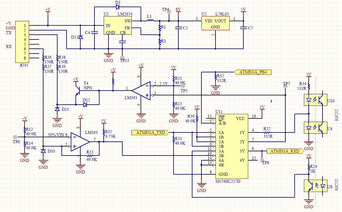
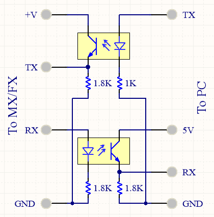
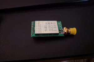
All it needs is a UART port and some opto-isolator hardware to convert it to the correct voltages.

Currently I am able to:

  • Get a status packets for the MX solar charger, FX inverter, and FLEXnet DC monitor
  • Get log entries stored on the MX (Up to 255 days worth)
  • Read & write MX/FX/DC registers, parameters, and controls (allows you to change system behaviour!)

Full protocol implementation details is available in the python library.

Leave a comment if you found this library useful!

  • 1 × Outback Power MX Solar Charge Controller
  • 1 × Outback Power FlexNET DC
  • 1 × MATE Emulator Circuit See project log for details!
  • 1 × Linux Board eg. Raspberry Pi, OpenWRT router, PC, etc.

  • Isolation Boredom

    Jared Sanson04/05/2020 at 05:38 0 comments


    So the current global pandemic and forced self-isolation has given me a great opportunity to really dig into the Outback MATE protocol, and I have figured out all of the important details! (documented on my GitHub project)

    I also started working on an Arduino-compatible library (currently far less featured) which is mostly useful as a way to convert the 9-bit MATE data to 8-bit PJON frames which mean I no longer need to use hacky methods in Python and can run things a LOT faster.

    uMATE gave me a convenient way to sniff traffic between two devices and send it to Wireshark:

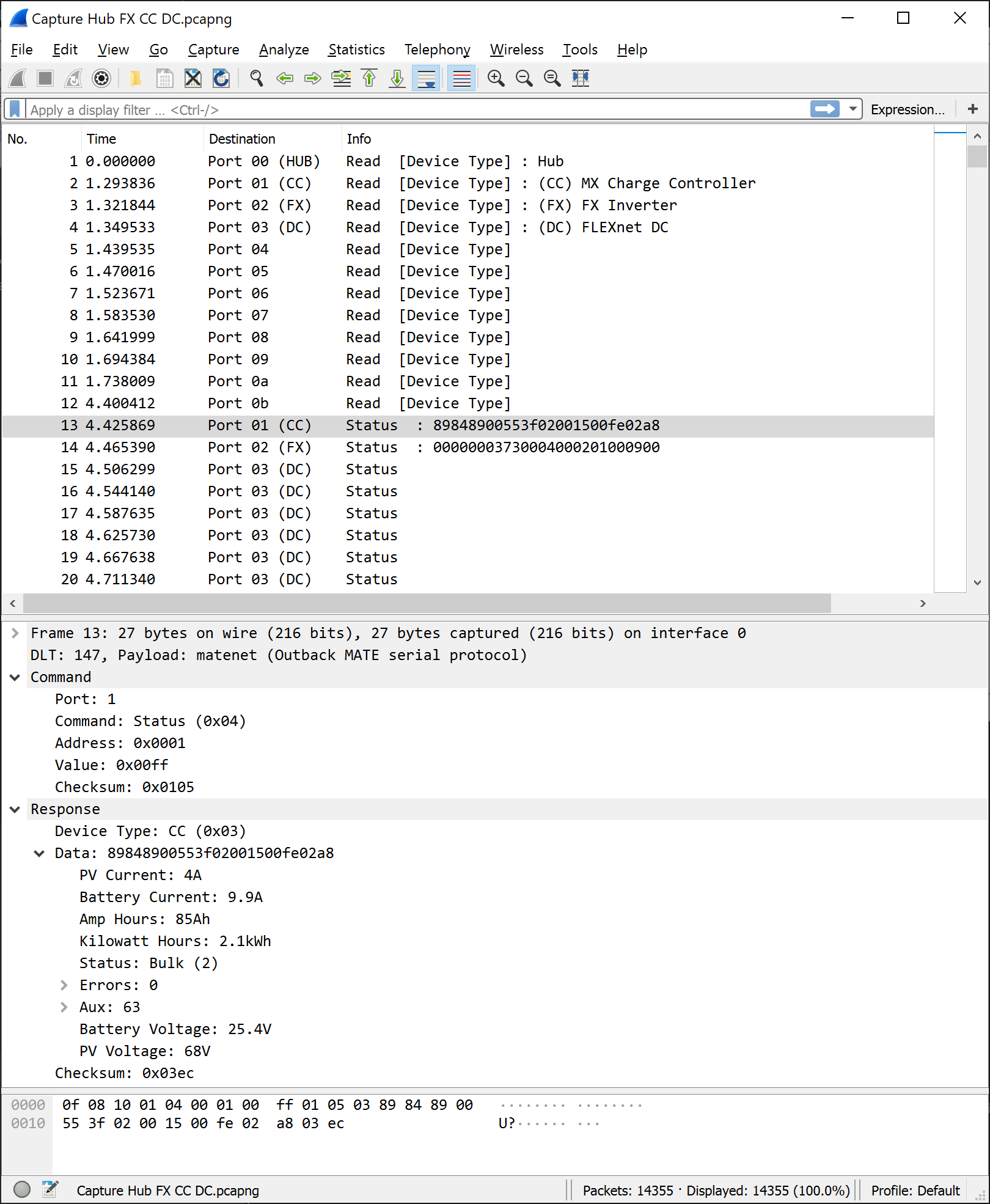
    This has been immensely helpful for figuring out the remaining details, as I can capture & monitor traffic in real-time and compare it with the MATE readouts. It helped me discover that the MATE actually synchronizes the devices every minute or so by reading/writing specific registers - and this is how the FLEXnet DC can know the date, time, and battery temperature without actually having an RTC or temperature sensor.

    I was able to discover the meaning of the remaining bytes in the MX status packet, and implemented status packets for the FLEXnet DC monitor.

    For full protocol details, see this page: https://github.com/jorticus/pymate/blob/master/doc/protocol/Protocol.md
    Bonus - my monitoring solution is now complete with the addition of a FLEXnet DC!Repos:

  • Data Collection & Grafana

    Jared Sanson01/16/2017 at 22:48 0 comments

    Using the information that I reverse engineered, I developed a Python2.7 library that can emulate a MATE device through a normal UART port. You can find more details about it on my website blog post: pymate.

    I set this library running on a small light-weight linux device (A Carambola2), which continuously collects information and uploads it to a remote server. I didn't do anything terribly fancy, just a simple python loop/queue which queries the MX inverter for status packets, decodes them, re-encodes them as JSON, and uploads them to my server via HTTP which then stores them into a PostgreSQL database.

    For a while I didn't do anything more, and just left it collecting data, until I recently stumbled upon a nice open-source project called Grafana. Unfortunately by default it only supports time-series databases (TSDBs), not regular databases like Postgres. I found someone's Github fork which adds SQL support, and was able to connect to my Postgres DB with very little effort!

    Now the effort of reverse-engineering their protocol has finally paid off!

  • Protocol Reverse Engineering

    Jared Sanson09/11/2015 at 07:25 0 comments

    The next part is to figure out how the protocol works, and the format of the data.

    I started with taking some live captures in a running system (A MATE connected to an MX charge controller), and looking at what kind of packets were being exchanged. The MATE behaves as a master, and all communication is initiated by it. No data is sent from the MX by itself.

    On start-up, the following packet is exchanged (presumably some sort of scan/ID packet):

    TX: 00 02 00 00 00 00 00 02
    RX: 03 00 03 00 06
    (TX is what the MATE sends, RX is what the MX sends back)

    And while on the status panel, the following packet is sent every second:

    TX: 00 04 00 01 00 00 00 05
    RX: 03 81 80 82 00 6A 3F 01 00 1D 00 FF 02 40 03 8E

    It's worth noting that the first byte in both TX and RX actually have bit 9 set. I wasn't able to capture this on my PC, which just treated the 9th bit as a parity bit. This is how they denote the start of a packet

    After observing a few packets, it became clear that the last two bytes were a checksum - but not a proper checksum - it was literally just the sum of all the bytes in the packet! (03+00+03 == 00 06)

    There were also some obvious patterns in the TX packet, like the second byte which seems to correspond to some kind of command or packet type (02 for start-up, 04 for requesting a status packet)

    I then tried matching the received status packet with the information that was currently on the screen, and was able to pick out some of the fields (status, battery voltage, pv voltage). Unfortunately the rest of the data proved elusive, but it was definitely encoded somewhere within the packet!


    I decided a different plan of attack was in order, since I couldn't see any other obvious patterns in the data. I started writing a simple MX emulator in python, communicating through my MATE adapter mentioned in the last progress log.

    It was able to spoof packets to the MATE, and I could then see the result on the screen and figure out what each byte did (or at least every byte that was visible on the LCD). By doing this I was able to figure out almost all of the status packet so I could correctly decode one sent from the MX unit itself. (Since the goal of this project is to replace the MATE and talk directly to an MX unit)

    Spoofing the status packet sent to a MATE unit

    At this point I decided to try spoofing some other devices which I did not have access to, such as an FX inverter, a Hub, and a FlexNET DC monitor.

    This was a bit trickier to spoof since I had no idea what kind of data the MATE would expect. Luckily I discovered that the MATE would actually tell me if the packet had an error if it was too short, so I just kept padding 0x00s until it reported no errors (at which point it showed all 0s on the LCD for each read-out). I was then able to poke each byte and see what effect it had on the LCD, and mostly determine what each byte did.

    The spoofing code I used is available in my python library, but the MATE adapter needs to have the RX/TX swapped since it will be connected to the MATE, not the MX/FX unit.


    The next thing I discovered was that some of the other LCD screens sent a separate packet, which appeared to obtain the value of one specific register (eg. battery voltage, relay status, etc.):

    TX: 00 02 00 44 00 00 00 46
    RX: 03 00 12 34 03 
    And I also discovered a similar packet was sent when I tried to control something (the MATE allows you to turn an attached inverter on/off):
    TX: 00 04 00 61 00 00 01 65
    RX: ??

    The full details of what each byte represents is available in my python library

  • Physical Layer

    Jared Sanson09/11/2015 at 05:45 2 comments

    -The Outback system uses a proprietary interface to connect the MATE to one of their devices over standard Cat5 cable. It can talk to multiple devices through the use of one of their proprietary hubs, or can just connect directly to the device. The RS232 protocol from the MATE unit is documented, but this proprietary protocol (what I call from now on "MateNET") is completely undocumented.

    Before I started attempting to reverse engineer, I guessed that the protocol would use some sort of standard protocol over RS485 - but I was wrong! After looking at the signals in a live system it was clear that the interface was not differential at all, it was just standard serial (UART) at 0-24V logic levels!

    The actual format of the bus is 9600 baud, 9n1 (yes, 9 bits of data - the 9th bit is used to signify the "address" byte, or the start of the packet)

    To figure out the exact pinout, I decided to reverse-engineer the MATE circuitry (since I had easy access to one I could pull apart). The circuit is pretty basic, it consists of a standard ATMEGA32, some EEPROMs (for logging), an RTC, a buck converter, RS232 isolation, and the MateNET interface. What suprised me is their use of a logic mux to switch between RS232 and MateNET - obviously because the ATMEGA32 only has one serial port!

    I have replicated the circuitry related to the MateNET RJ45 port below: (This does not show the EEPROMS/RTC/ATMEGA)

    The pinout of the MATE is as follows:

    1: +V (Battery Voltage)
    2: GND
    3: (TX:MATE -> RX:MX/FX)
    6: (RX:MATE <- TX:MX/FX)
    Note that these use the standard ethernet pairs (Orange/Green pairs).

    Creating an adapter from the above schematic was easy. I decided to forgo the comparators, and just use some opto-isolators (which also guarantees my linux board will be isolated from the charger)

    This opto-isolator can replace the MATE, or a MX/FX unit (for testing - this allowed me to poke values at the MATE and helped me figure out the packet formats with much finer detail than I could have by simply capturing and observing them!)

    To connect the adapter to an MX/FX unit using an RJ45 cable:

    Opto-Isolator <> MX/FX
    +V  : Pin 1 (Green/White)
    GND : Pin 2 (Green)
    TX  : Pin 3 (Orange/White)
    RX  : Pin 6 (Orange)

    To connect the adapter to a Mate:

    Opto-Isolator <> MATE
    +V  : Pin 1 (Green/White)
    GND : Pin 2 (Green)
    TX  : Pin 6 (Orange)
    RX  : Pin 3 (Orange/White)

    (Note the swapped TX/RX)

View all 4 project logs

Enjoy this project?

Share

Discussions

Jim wrote 02/13/2024 at 19:13 point

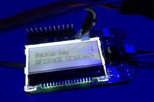
Thanks for posting all this wonderful work.

I have a 48V system and noticed the Vbat on the RJ45 connection of the FlexMax is about 22V.  Does this make any sense?

  Are you sure? yes | no

Jim B wrote 09/21/2021 at 16:21 point

Hi Jared,

Thank you for this great project

I would really like to get this up and going, I live off grid in Baja Mex and USA Oregon.

Both systems have Flex Max Charge controllers. I would especially like to be able to monitor the systems while I am away. I have electronic hardware skills but my software is mediocre at best, but when motivated I can usually patch things together.

What is the minimum raspberry Pi that you would recommend to be able to send the data via WI FI.   

Best Regards,

Jim B

  Are you sure? yes | no

Jared Sanson wrote 09/26/2021 at 11:38 point

Any RPi will work, you will just need a USB-UART(TTL) dongle and appropriate opto-isolator circuit. Unfortunately I don't have a good standalone software package you can use so it'll need some plumbing to get the python library to send data where you want it.

Alternatively you could also consider an ESP32 for which I have written an almost-complete firmware that sends the data to MQTT:
https://github.com/jorticus/mate-mqtt-gateway

This might be easier to get up and going, plus it's more reliable than my python implementation.

  Are you sure? yes | no

Jim B wrote 10/06/2021 at 13:35 point

Jared,
Thank you. I appreciate your answer. I like easy and stable! I will get some hardware on order so I have it to take to Baja. I am distracted re-siding our place in the north right now. A fall project that needs to get done while the weather cooperates.

  Are you sure? yes | no

jevargas-m wrote 06/04/2020 at 13:59 point

Hi Jared, this is a cool project congrats. I'd love to try it in my system, its a Flex60, Flex80 and FX. I'd love to track the parameters of the three of them and develop an enhanced Mate app with some cool info.  Particularly for me tracking when batt is floating and there is surplus sun is very helpful as I can turn on some amenities in the house like the pool pump :)

I have some CS background but not electronics or programable boards, though would be great to contribute any way I can; I'm thinking on connecting each of the above and connect them via wifi to send their output to a mysql database, what would be your recommendation for hardware, having each connected to an ESP8266 or the three of them to a Raspberry ?  I also see you are trying to port to arduino, if I can help, at least testing I'd be very happy to do it.

  Are you sure? yes | no

Chris Hellin wrote 05/06/2019 at 08:06 point

Hi Jared, excellent work.

I've been following your project for quite a while and using your information managed to get comms to my MX60 using a Raspberry Pi, via an Arduino (the serial port on the Pi was connected to a BMV600s battery monitor). I used level shifters rather than opto-isolators, because I had transistors and resistors but no opto-isolators, and that worked with no problems.
The Pi produces a web page on local wifi with current battery state, and a graph for the last 24 hours, and also writes 24 hour log files.

As this seems to be an ongoing project, I have a request for information. My MX60 is now getting on in years and the rubber buttons are failing. I have 3 options.
1. Open up the MX and solder on some wires and pushbuttons.
2. Buy a Mate :(
3. Get the Pi/Arduino to do the virtual button-pressing, if possible.

What I would like is the serial data for starting an equalise; voltage, time, GO!
Any other settings that are possible from the Mate would also be a bonus.

If you are now onto other things I fully understand.
Regards,
Chris

  Are you sure? yes | no

Jared Sanson wrote 05/16/2019 at 05:25 point

I wish I could, but the mate I've been using is on the other side of the world right now (in New Zealand), and I can only test it out when I visit :)

How did you use the Arduino to talk to the MX60? Did you port my python lib to Arduino? I'm actually working on something similar myself, so it might be good to combine our efforts

  Are you sure? yes | no

Chris Hellin wrote 05/16/2019 at 11:42 point

I actually used an Arduino compatible Teensy 3.1 - https://www.pjrc.com/teensy/

It has 3 serial ports (6 on the newer models). They also have a plugin for the Arduino IDE (see Teensyduino in the menu).

Something that will make things easier is the fact that the Teensy serial ports can handle 9 bit data in hardware, and it's supported in their library - Serial.write9bit(). I extracted what I needed out of your Python library to get them talking.

The Teensy remains plugged into one of the RasPi's USB ports and a virtual serial port is established between them. Teensy grabs data from MX60, formats it, sends it to RasPi. That's as far as I've got, hence my request for more information ie. sending commands and settings to MX.

I'm quite happy to help, but without a Mate to play with (lol) I'm a bit stuck.

  Are you sure? yes | no

Jared Sanson wrote 04/05/2020 at 05:20 point

Hi, you may be pleased to know that I've figured out almost all of the details of the MATE protocol, and created a new Arduino-compatible project (https://github.com/jorticus/uMATE/) that makes use of the native 9-bit UART.


It should now be possible to run completely without a MATE, even being able to configure various settings (though I have not tested this or added it to the library, so you'll need to do some work to get this going)

  Are you sure? yes | no

Chris Hellin wrote 11/16/2021 at 13:45 point

Hi Jared, I looked on here again last Friday and saw your updates. After a weekend of coding and building a quick interface circuit I can now switch between Equalize and Bulk, which is what I needed most. I can also set voltages, times, etc., which may be handy in future because only one of the buttons on my aging MX works without some 'coersion'.

When I get time I'll add the functionality to my PV monitoring system webpage, rather than having to use the Serial Monitor on the IDE.

The level-shifter circuit I use is here: https://tinyurl.com/yh6rrhpj
It may be of use to someone.

Thanks for sharing your experiences and the knowledge you've aquired.

p.s. I've been searching for a flag for MPPT mode. Have you come across anything?

  Are you sure? yes | no

Joshua wrote 03/12/2018 at 16:24 point

Have you figured out if the Outback HUB is a proprietary unit as well or will any regular ethernet hub work?  I'm going to test this program on my FLEXmax charge controller but I don't have any other Outback parts (yet).  I have built an energy use monitoring circuit that I can incorporate (equivalent of the FLEXnet DC) but would rather forego the purchase on the proprietary hub.

  Are you sure? yes | no

Jared Sanson wrote 03/13/2018 at 01:59 point

The hub is not ethernet, so no, an ethernet hub won't work. It looks pretty simple though and I think you can do without one, unless you need to do a fancy 3-phase inverter setup where there's some kind of synchronization that the hub performs. Otherwise you can just use multiple serial ports and hook each device to a separate port.

This is how I think the hub works:
- The mate connects to port 0 and is the master
- Devices connect to ports 1-9 and are slaves. They do not talk to each other, except in a 3-phase setup where there's some kind of out-of-band synchronization signal.
- The packet has a port field (0-9) which specifies which port the communication is for. When the hub receives a packet, it fills this field in to match the port that the packet came from.
- On startup, MATE sends some kind of discovery request, and each device returns a response packet. the Hub will set the port field, so the MATE knows which device is connected to which port. (MATE always initiates commands)
- If there is no hub, the port field will always be 0.

  Are you sure? yes | no

Joshua wrote 03/13/2018 at 02:10 point

Alright, that really doesn't seem too bad.  It can be entirely replicated in software it sounds like.  I'm working with an ESP8266 and with the ability to load MicroPython firmware, I think I'll play around with your code running on that.  I'm only a couple months into the programming/electrical engineering hobby world so I am a long road ahead of me.

  Are you sure? yes | no

Adam Dale wrote 01/17/2017 at 19:53 point

Hi Jared, love this project, and as I read I feel your struggles. I wanted to know if you could update me on where you are on this? Did you figure out the last bit (no pun intended lol) of your issues. I am working on a solar project right now with the tracer 2210 but I recently ordered an FXR2524A and Flexmax 80 MPPT controller so I will be learning how to RE that very soon. I'm trying to save money and did not want to pay $350 for a MATE3 that I could RE. I'm primarly a Java guy but I wanted to see if you could tell me more about the protol. I seen you where having trouble with understanding some of the responses or sending data, could it be something with sending CRC that would be causing some issues?

  Are you sure? yes | no

Jared Sanson wrote 04/05/2020 at 05:22 point

Hi, I know this was a long time ago, but I've now figured out almost all of the details of the MATE protocol and you could probably run without a MATE. (Though actually configuring things has not been tested)

  Are you sure? yes | no

Jordan Hazen wrote 10/31/2016 at 01:35 point

hi Jared, great work!

Could you consider posting some bits of your Python code to the Downloads area of this project page?  I tried to visit http://jared.geek.nz/pymate but that site is down at the moment, returning a "502 Bad Gateway" nginx error.

I have a grid-interactive solar system with a GVFX-3524 inverter, FM-60 charge controller (slightly improved MX-60), Flexnet DC, Hub4, and assorted non-Outback bits, and am most interested in improving options for computer control of the system -- with newer firmware in the Mate and other devices, log output via normal RS-232 is much better than it used to be, but the mate still only interprets a tiny number of commands from the computer, requiring most configuration to be done from its own keypad.  This may be partly a consequence of the shared Atmega serial port, which they don't want unsolicited command strings from the PC to get too long or complex.  Even just sending simple Grid Drop/Use, Inverter On/off, etc. sometimes has to be done twice before it takes effect, though my timing could be a little off-spec.

  Are you sure? yes | no

Jared Sanson wrote 10/31/2016 at 02:02 point

Sorry, something broke in my server config, should be fixed now! (The code's also available on my GitHub)

I think it should be possible to control things with this reverse engineered protocol, though I haven't tested it. I started with just the MX charge controller which doesn't really have any controls, but I did observe some control packets sent from the MATE unit when I activated a control.

  Are you sure? yes | no

Rollinns wrote 01/30/2017 at 23:06 point

Jordan,

I read this "and assorted non-Outback bits" 

I have the communication protocol info for the Magnum inverter units.  After searching on the web for a long time I found it and kept a copy, when I tried to ask the lead engineer some questions I got a "we'll get back to you" and it's been a few years.  My situation changed and I didn't need a smart controller for my generator anymore so the project fell off my list.   Message me if you want a copy of their protocols.  I'm not sure how it got out but the engineer was not happy I had it.  It laid it out bit by bit.  With that info, you could probably easily have the RasbPi control anything Magnum and Outback.

  Are you sure? yes | no

ahmad_fayek wrote 10/29/2016 at 18:23 point

great job, thanks!

how can I access your code?

  Are you sure? yes | no

Jared Sanson wrote 10/31/2016 at 02:03 point

You can find it on my website (http://jared.geek.nz/pymate) or on my GitHub (https://github.com/jorticus/pymate)

  Are you sure? yes | no

jmpullara wrote 01/15/2016 at 06:53 point

Excellent project Jared.  It's about time somebody did this!.  

FYI  in case you didn't know - boB Gudgel (comment below) is the designer of the Outback MX charge controller (and maybe the Mate as well - I'm not sure). 

  Are you sure? yes | no

Saamir wrote 01/10/2016 at 16:47 point

What a surprise to find this on the web. I have done almost all of what's described here. My current goal is to build a board that plugs into a Raspberry Pi, that has 4 cat-5 connectors, that talk Mate proprietary protocol. I have version 1 done, but have struggled to get the Pi talking 9-bit data. So version 2 is underway, which has a Pic with 2 uarts, one to Outback, the other to the Pi. I have a prototype working. I also have a protocol document written, although there's probably very little in it that isn't already known. I'm happy to share what I have.

  Are you sure? yes | no

Jared Sanson wrote 01/11/2016 at 21:10 point

Haha nice, it's such a niche area I wasn't sure if anyone had done anything on it (And my searches of the forums didn't turn up much)

The 9-bit communication definitely makes communication tricky, and if you've looked at my code you'll see I faked it with parity bits, which I think should work on the RPi. I'm actually ignoring the 9-th bit on receive, but it still seems to work. The separate PIC is a much more reliable way to do it.

It'd be great to compare your analysis of their protocol, because I'm not 100% sure I've got everything right. Do you have any links I can look at? 

  Are you sure? yes | no

boB Gudgel wrote 01/08/2016 at 18:10 point

Congratulations Jared !  I wondered how long it would take someone to RE this system.  You are one of the first, if not THE first one that I know of to do this.

  Are you sure? yes | no

Jared Sanson wrote 01/09/2016 at 00:30 point

Thanks! I enjoy a good challenge, and I couldn't leave all that solar charging data left untapped ;)

If you ever make use of my code I'd love to hear how it goes, and let me know if you run into any problems.

  Are you sure? yes | no

Similar Projects

Does this project spark your interest?

Become a member to follow this project and never miss any updates