 ben biles
demo with quite bad antenna on reciever...
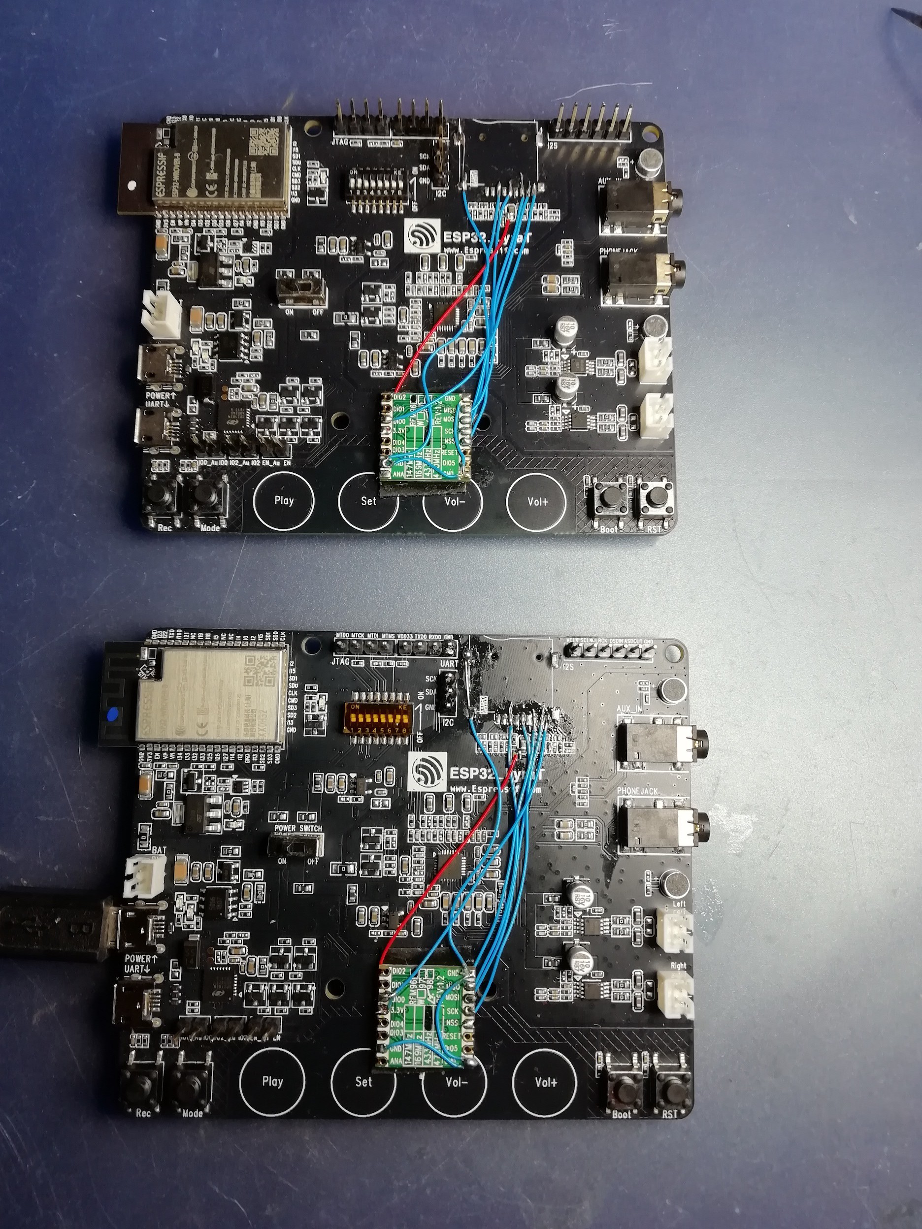
word of warning, if anyone wants to make wireless mics with the CC8530 and AIC3101 using the bias power to run a mic, there is some quite bad RF noise around 300hz.. I would check the TI forums about this issue before considering using the CC8530 or CC85xx chips. You can filter the noise if your using a TI codec with miniDSP build in.
 Joe
Joe
 Chris G
 Simon Merrett
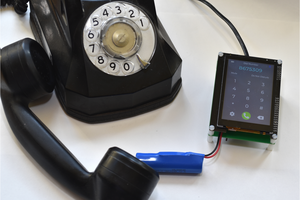
 Dan Julio
Do you need 48KHz? If you're only doing 8-bit resolution, presumably sound quality is not paramount.
Halve, or quarter, the sample rate. 12KHz is easily good enough for speech. They only use 8KHz on landline telephone networks. Either discard 3 out of every 4 samples, or average them together. Add all 4, then bit-shift right, twice, for a quick divide by four.
Or you could implement ADPCM as the other poster mentioned. Or the simpler version, DPCM, that's pretty simple, really just the difference between each sample. You could look up a tutorial on it, or maybe get lucky and just paste in somebody else's code!
Since you're only doing speech, where low data rates are acceptable (and desirable), you can use the more simple compression techniques that are possible on a low-powered CPU.