 zakqwy
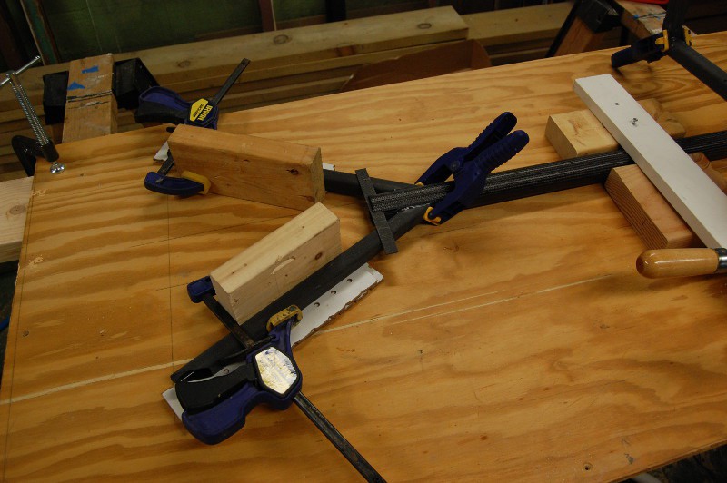
Today I focused on GimbalBot's main frame. Or I should say, a part of the frame--specifically, the joint between the 40mm CFRP tube and the two diagonal 23mm square CFRP sections. I figure this is the hardest one to do, and it needs to be as close as possible to perfect; I need the upright square tubes to be fairly well aligned so the bearings turn freely. Furthermore, this is the only glue joint that doesn't mate two large flat surfaces together; while I'm hoping I have enough surface area epoxied between the rounded square tubes and the trapezoidal gussets, actual gluing performance depends a great deal on fitment precision. It's also not lost on me that the raw material value of the CFRP chunks alone is around $150ish, plus a decent lead time. So yeah, I measured about fifty times before cutting.
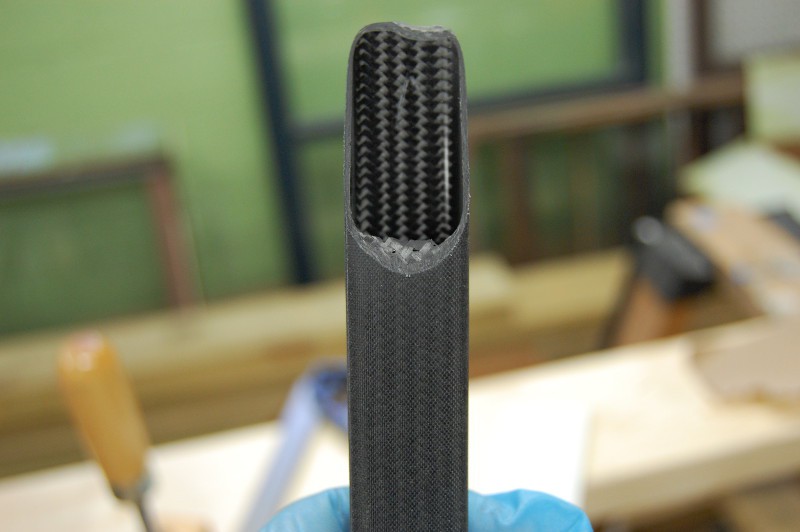
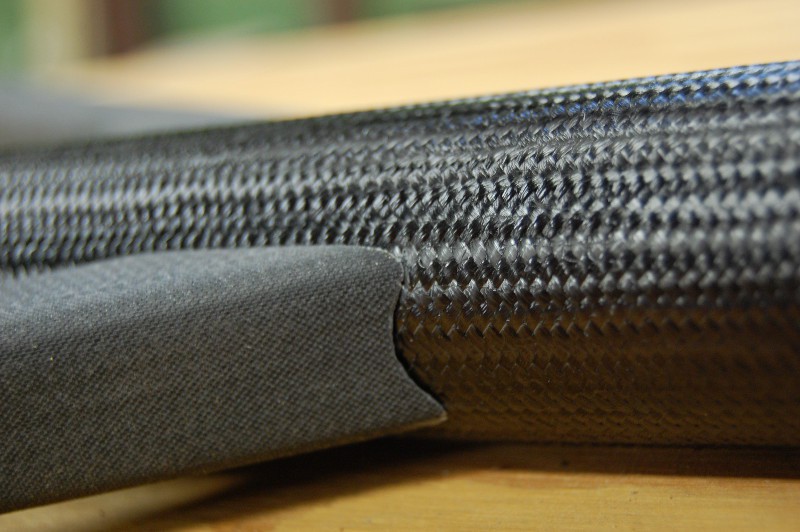
First, a close-up of the joint itself:
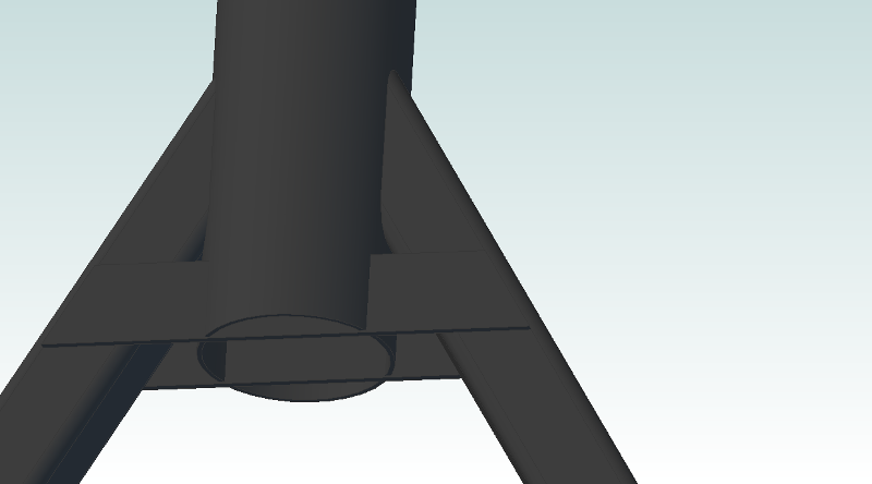
It may not be obvious here, but the two square tubes have their ends rounded at an angle to match the OD of the 40mm frame tube. The gussets fit in slots; ideally, these slots should be angled to maximize available surface area for best epoxy performance.
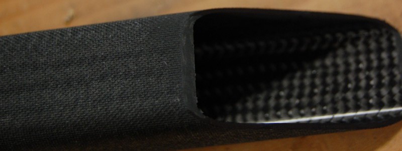
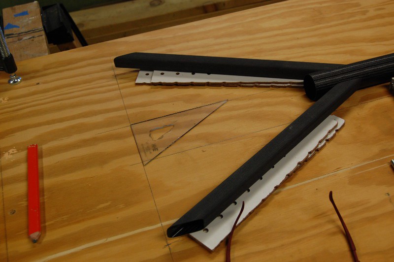
I cut the square tubes at a 30 degree angle and a few millimeters long compared to the print; after sanding each end to the proper angle and length, I marked the sides black to avoid reducing the overall length in the next step:
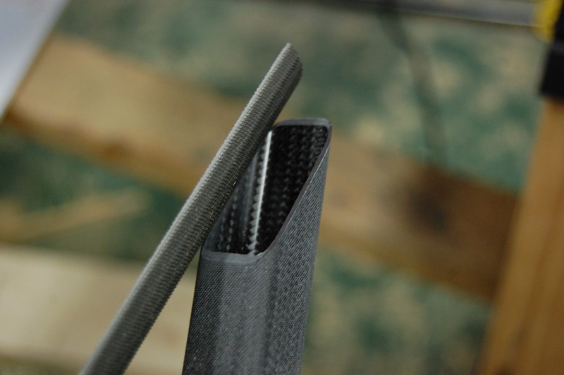
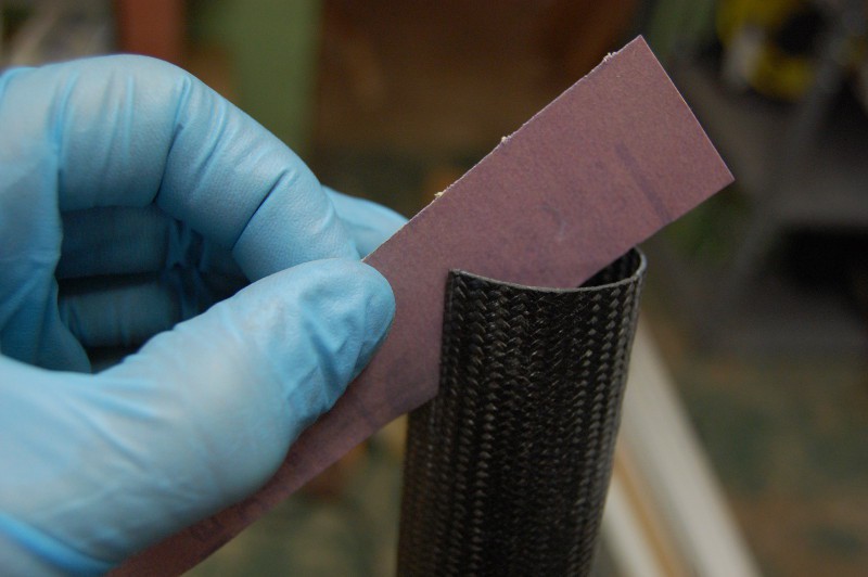
Using a half-round bastard file, I started to shape the top cut of each piece to fit the round tube:
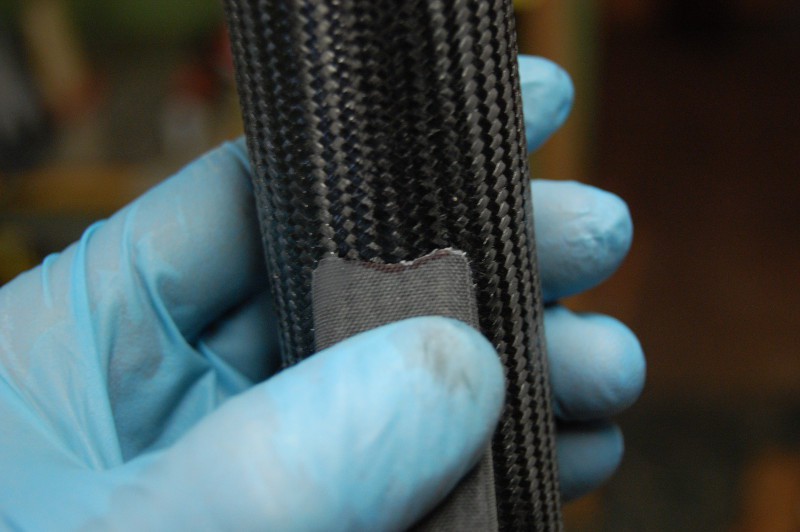
I checked the fit many times against the round tube, sometimes marking off the material that needed removal:
After a few minutes with the file, thin fiberous flash started to build up on the lower curve. I knocked this off with the edge of the file so it wouldn't cause me to overdo the cut (the top hasn't been touched much here, so it's quite uneven):
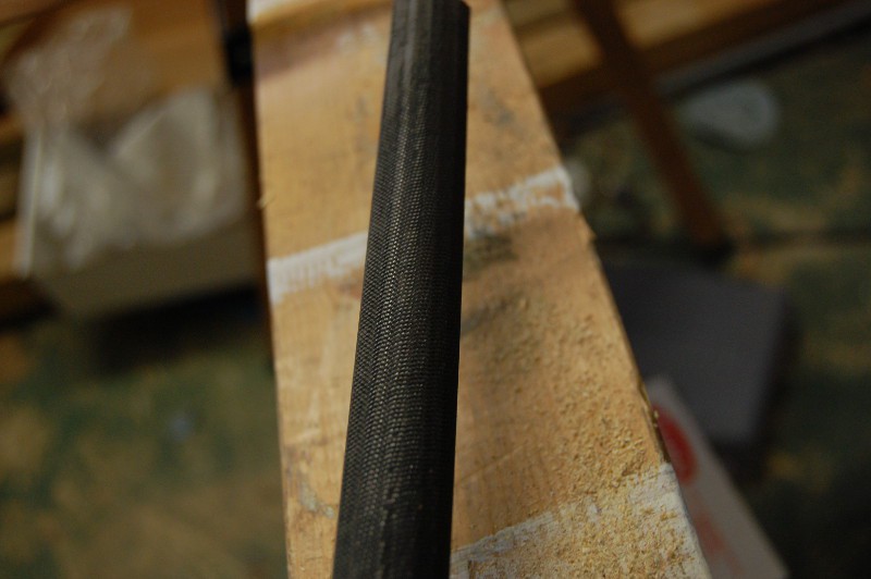
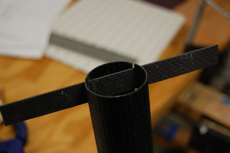
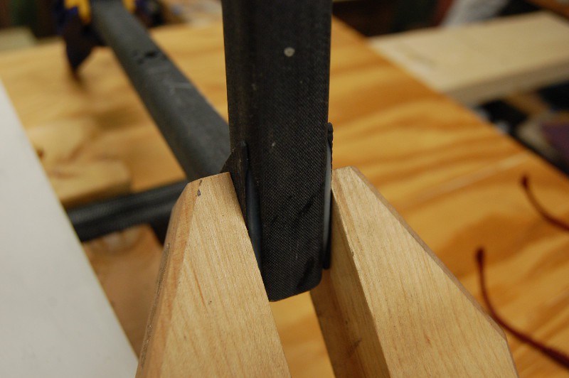
Periodically, I'd check various ends against each other by holding them flat against a board and examining the gap. After a bit of tweaking, I was able to interchange all four ends freely without gaps, suggesting that the angles (while maybe not quite 30 degrees) were identical:
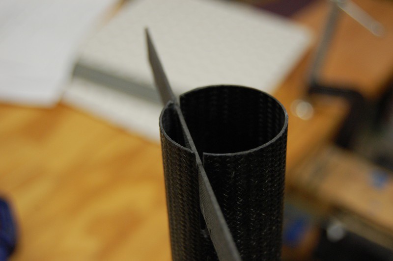
I also held the rounded square tube against the center tube while the round bit was flat on a board; this allowed me to roughly check the squareness of the filing job:
My brand new half-round bastard file was not stoked about its first job, but it performed its function admirably. It's not terribly obvious here, but the shiny marks on the file teeth are bent or rounded off edges. I'd love to find a WC version of this tool, or a half-round diamond impregnated tool of some kind:
The perfect is the enemy of the good. I kept trying to improve the fit until I ran out of excess material:
I needed to hold the square tube stock 8.5mm above the edge of the 40mm center tube to match the assembly drawing. I figured out that a bit of scrap pegboard I had lying around was 4mm thick; two pieces stacked up is close enough for GimbalBot. I also built a clamp (shown later) to hold the center tube in place. After marking the center tube to align the two square tubes, I held them in place and dropped marks using a square onto the plywood base. Connecting these marks and checking the angle between that line and a line parallel with the 40mm center tube gave me an idea of the square tube misalignment; no protractor here (just a handy 30-60-90 guide), but I estimated it at ~1 degree or so:
Time to mark the center tube for slots. First, I built a jig to keep the square tubes in alignment and allow me to clamp them securely in place. Once these were sturdily aligned, I used a scrap piece of 1.6mm CFRP and a WC scribe to mark the slots:
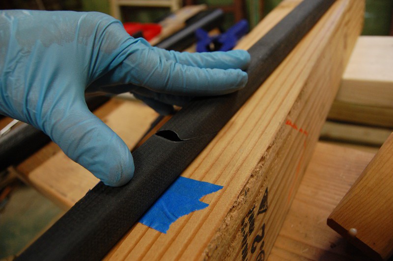
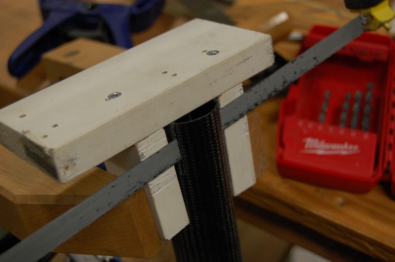
Including the angle of the 1.6mm reinforcing gusset, I needed to cut four ~2mm wide slots into the 40mm tube. Both of the tools I'd used previously--the carbide hacksaw blade and the diamond impregnated jigsaw blade--had kerfs thick enough to cause issues. As such, I opted to dull up a hacksaw blade instead. I built a quick jig to keep the saw between the lines on either side:
Then sanding. Lots of sanding. Many grits and paper configurations. I taped the inlet of my vacuum cleaner to the bottom of the tube to suck up dust during this part:
Many fit checks on the sanding. I needed a consistent 30mm-long slot. This took time:
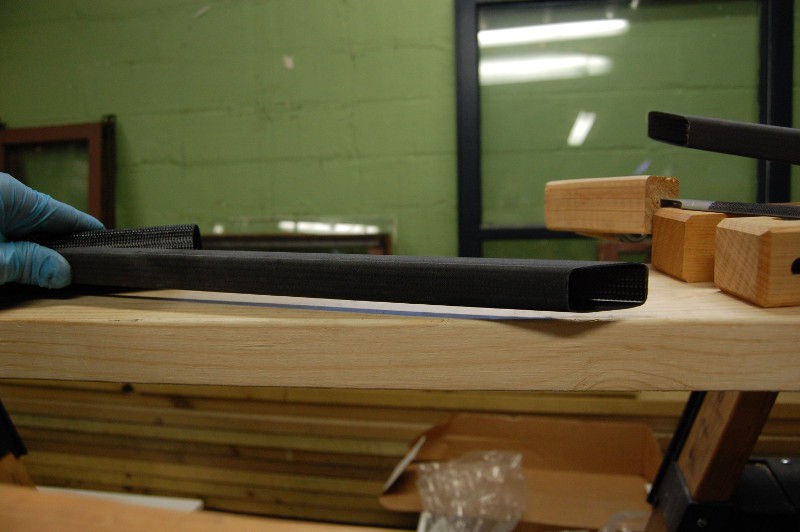
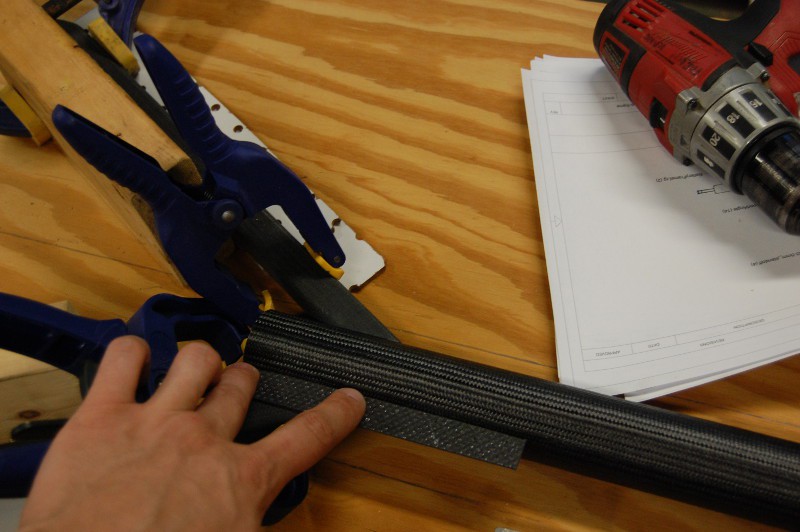
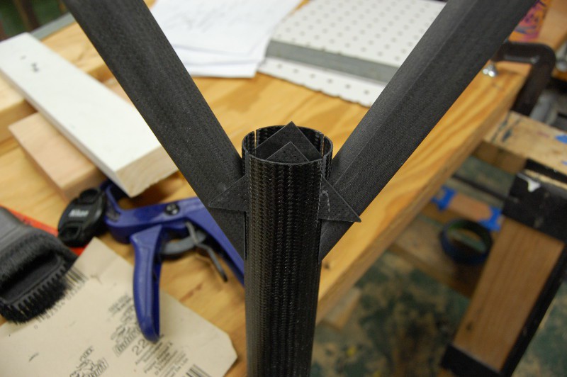
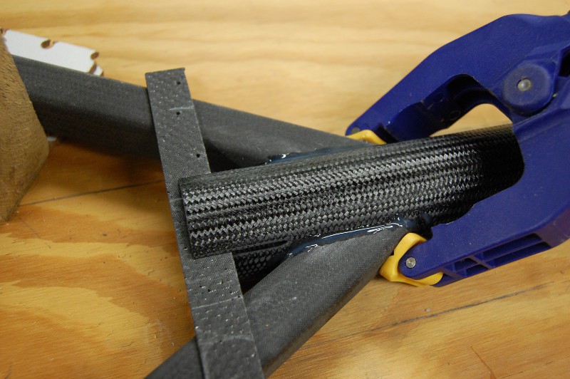
This was a big moment. I used a pair of gussets that still needed to be glued to the pitch ring to test clearance between the two slots. It was close enough that I was able to friction fit the joint together; the two square tubes are unsupported in this photo, held in place entirely by the clamping force of the two gussets:
Time for gluing. This picture also gives a better overview of the alignment jig (the 2x4 scraps are all screwed in the from the other side of the plywood):
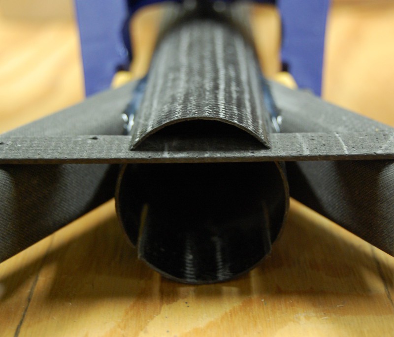
Close up of the joint, showing a piece of 1.6mm CFRP being used in the top slot to ensure rotational alignment of the 40mm tube. It was tempting to overdue the glue fillets, but I'm guessing they're something of a peel liability if they get too big:
Another view of the glue joint. I'm happy with how this turned out.
While I had the Space Glue out, I also adhered the remaining four triangular gussets to the pitch ring:
In a hilarious twist of fate, it seems that my previous assumption--that using square tube stock for the motor mount would leave me with enough to finish the project--was incorrect. I am 3" short out of an 8' section, so I'll be ordering more tomorrow along with longer screws and assorted other forgotten parts. Several work and house things happening this week, but with any luck I'll get a bit more construction work done Thursday or Friday evening.
- Zach
Discussions
Become a Hackaday.io Member
Create an account to leave a comment. Already have an account? Log In.