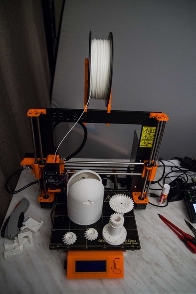
The Thor robot is going to be build on my Original Prusa i3 Mk2 printer. This printer can in theory print a 200x200x250 cm object but some part of the Thor is too big.
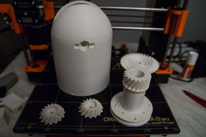
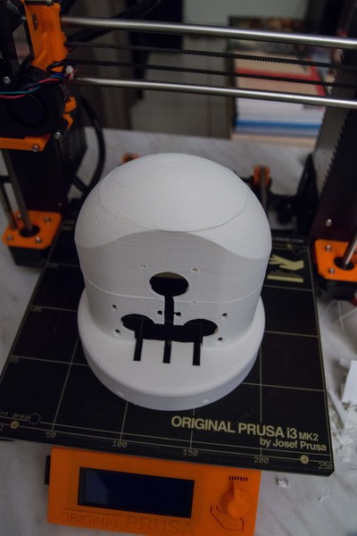
This big dome is called Art4Body currently using ABS filament with %20 infill, 4 top and bottom layers and 3 layers as outline (190 g of filament used) and prints in 11 hours. Art4Body is basically the upper arm of the robot.
10 hours into the print I ran into an issue with my extruder and it halted the print. Unable to continue I had to find a way to print the top part. Since I use Simplify3D I could estimate the Z layer, and move the model down. Simplify3D created the gcode to start from that layer on.
I finally glued the top and bottom part. Willit be structural strong? I have no idea, but when I press that dome thenI think an Elephant can stand on it.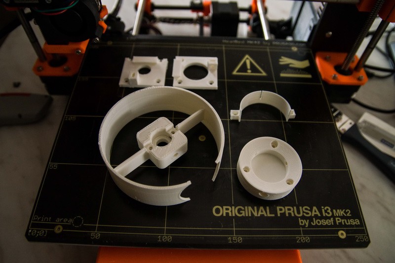
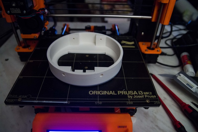
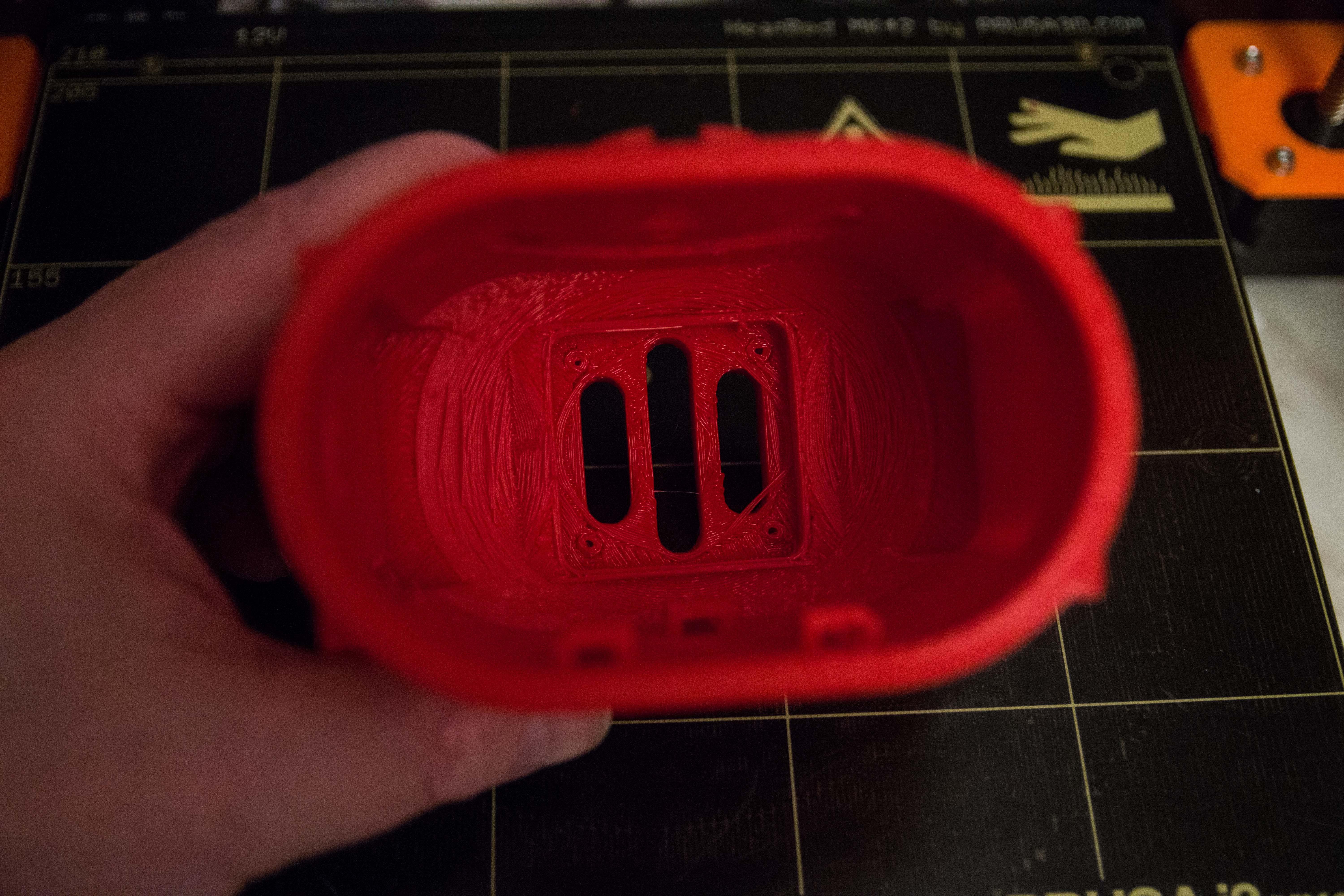
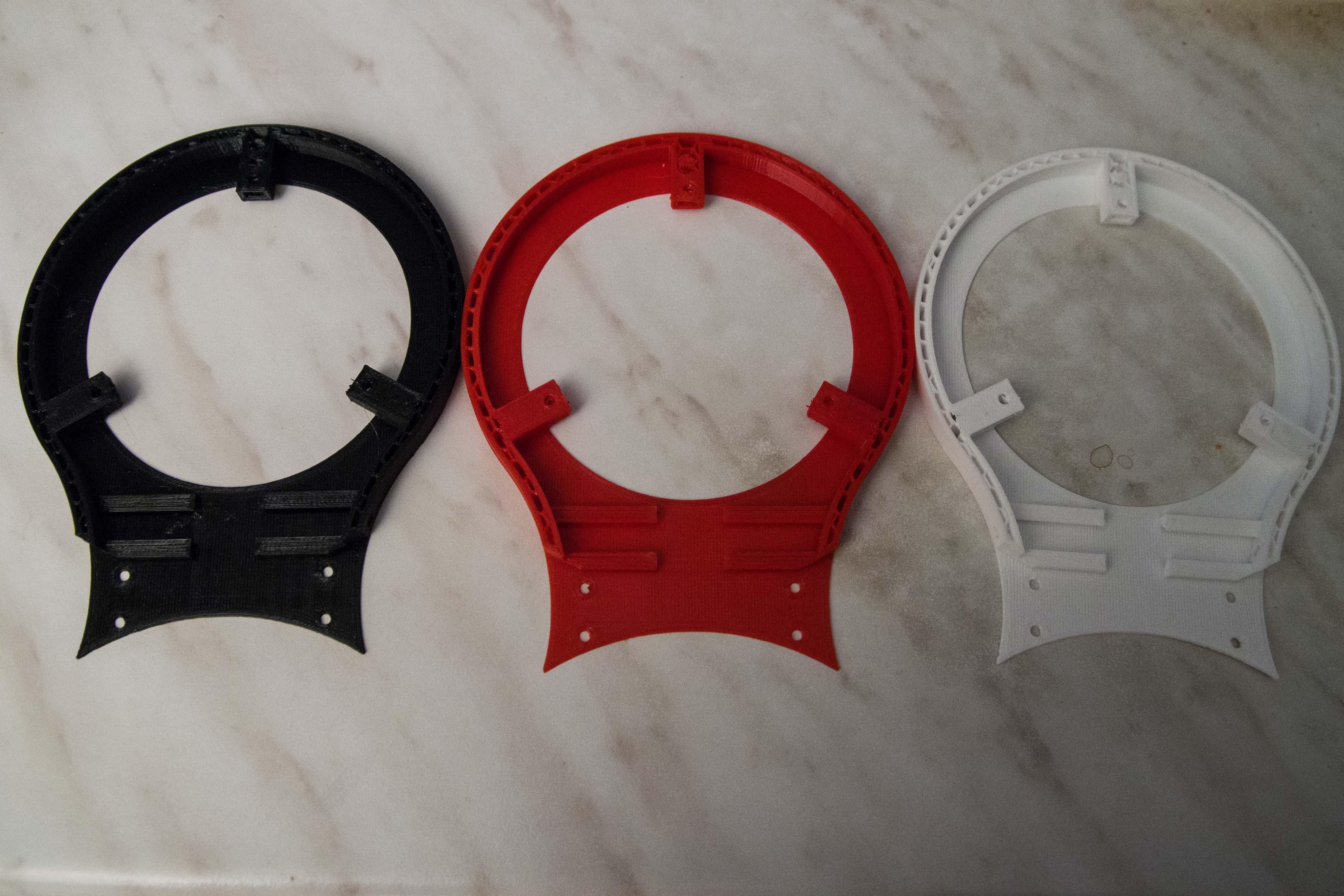
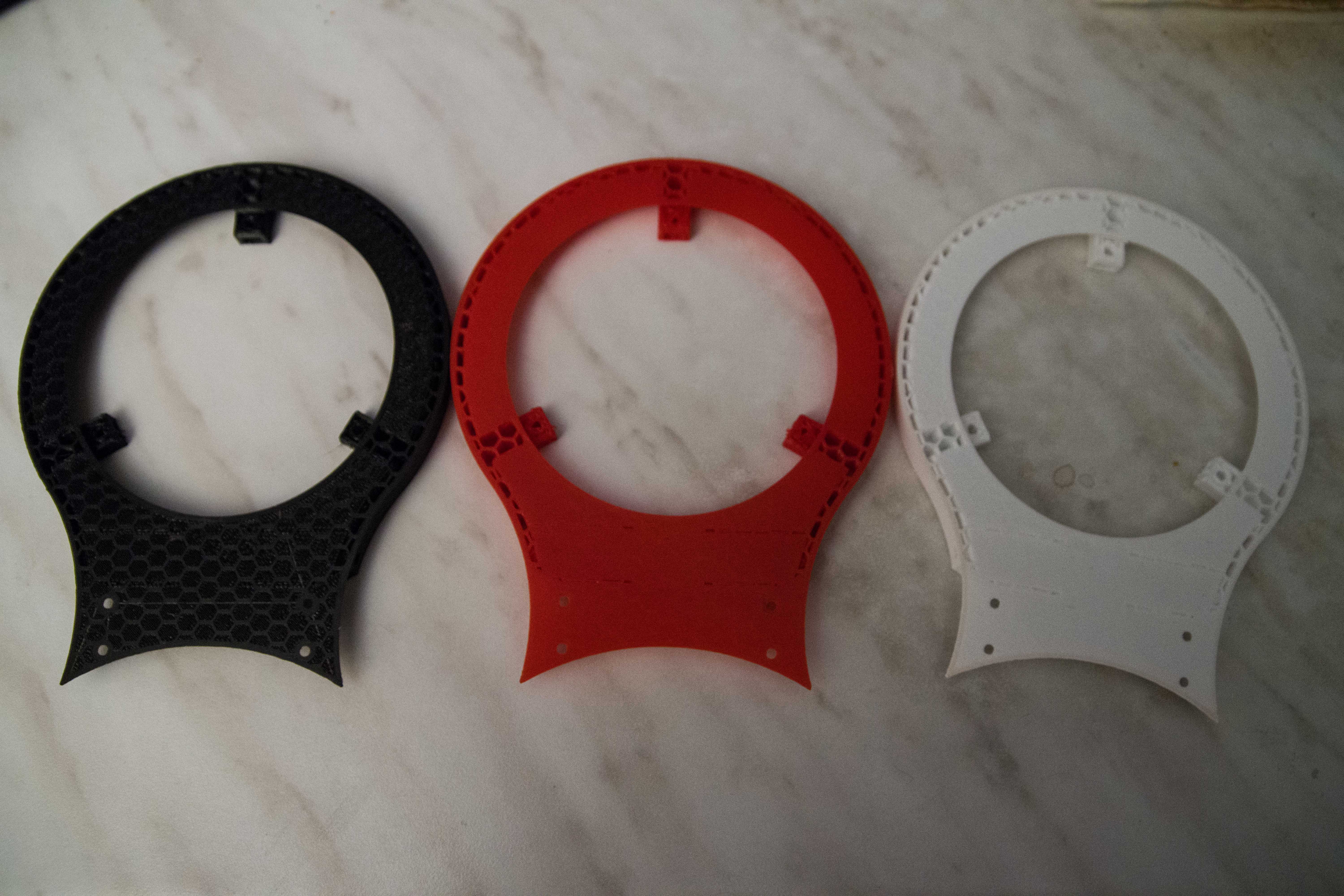
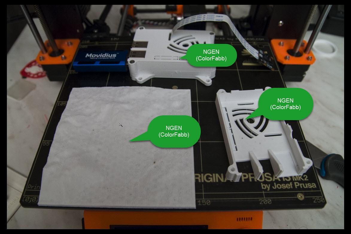
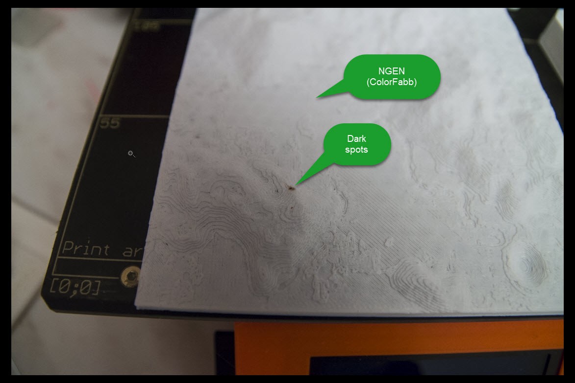
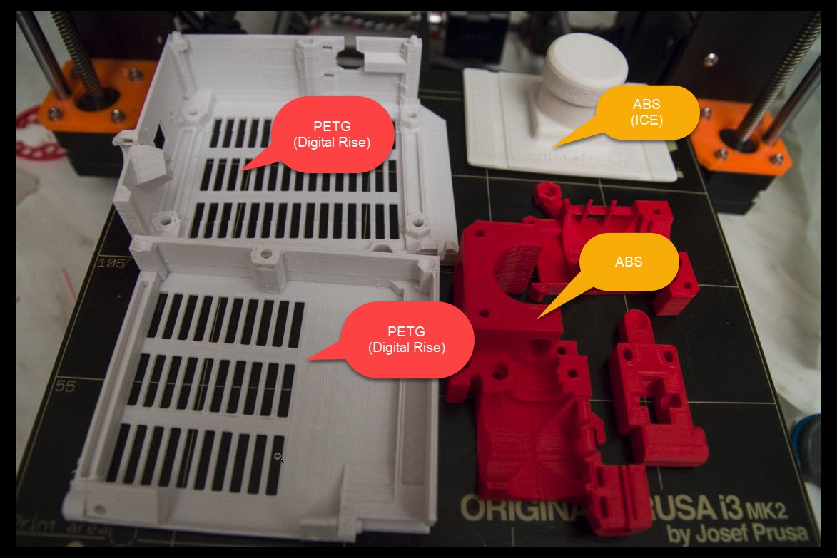
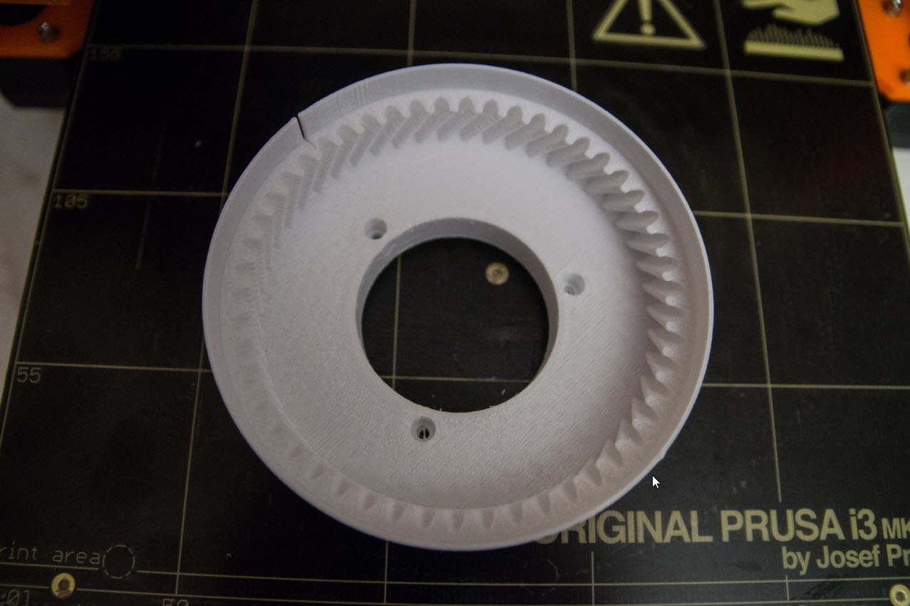
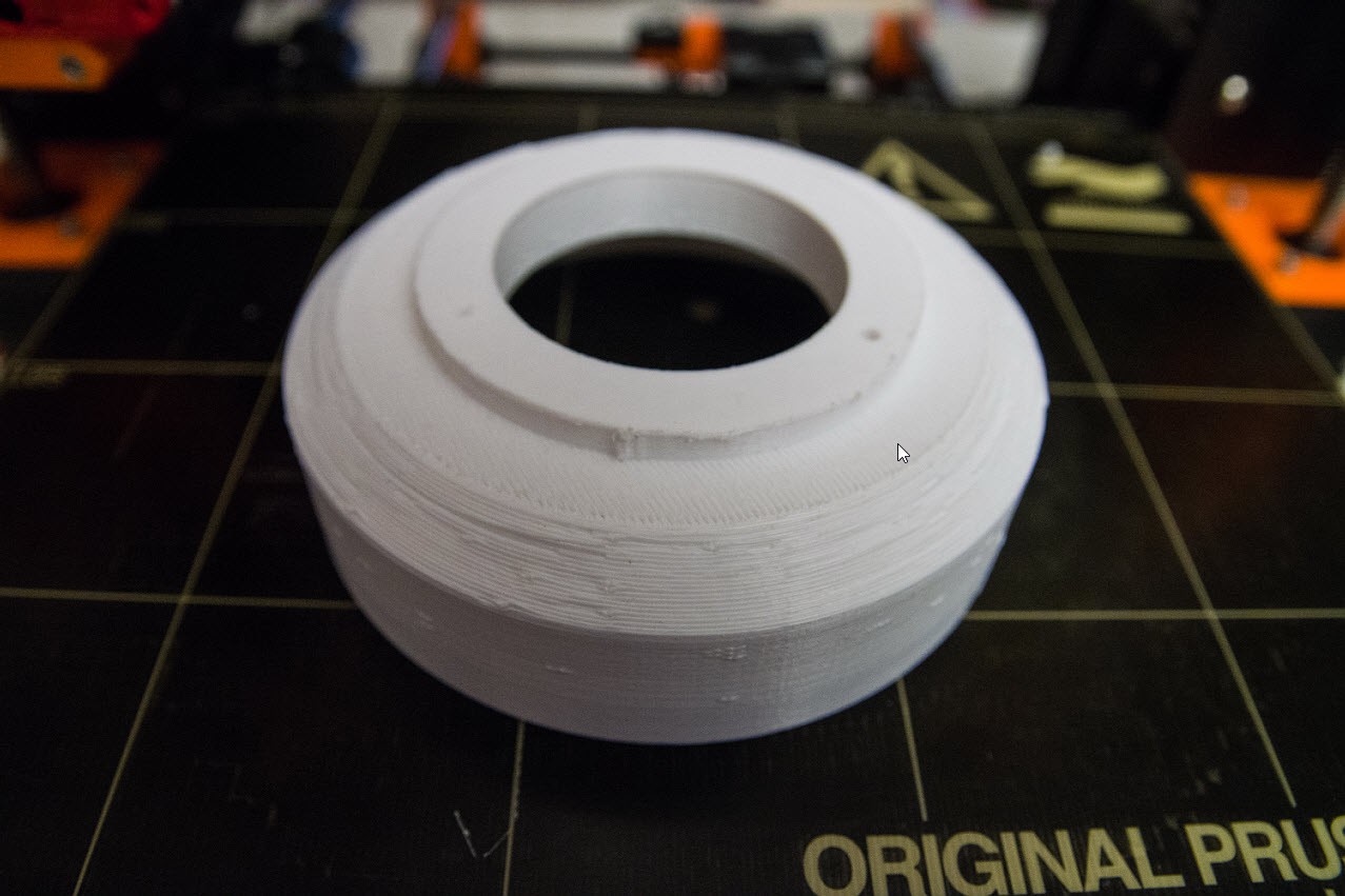
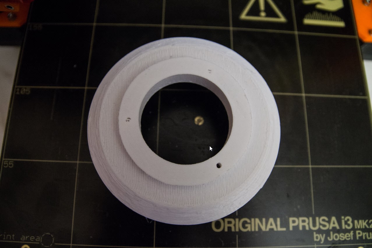
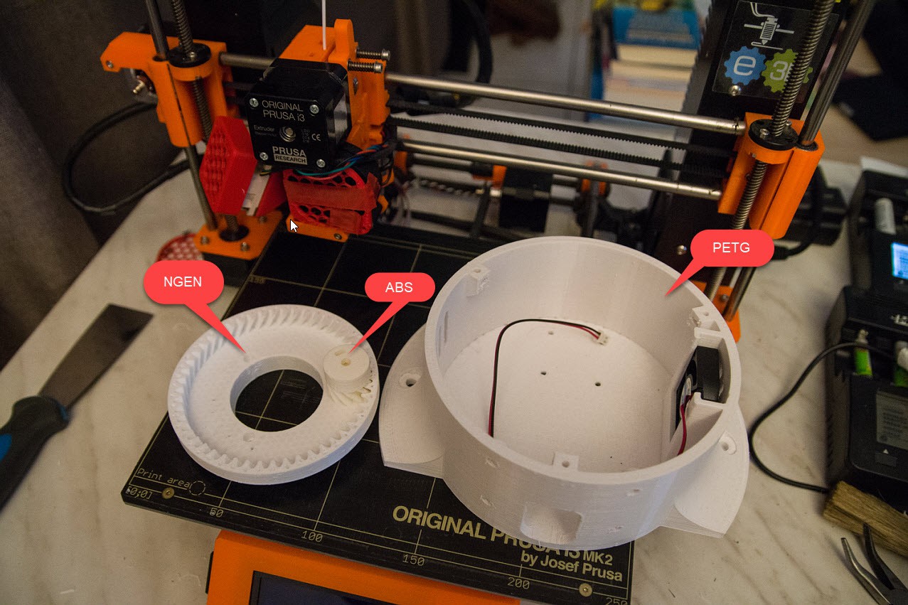
Printing more parts Art56CoverRing, Art32Optodisk, Art56Interface, Art56MotorHolderA and B. Infill 20% 0.3 layer height and took 3.5 hours. I think it is wise to use ABS plastic because some walls are very thin.
I do not have the motors, electronics, bearings,.....yet. Still figuring out where to order them from. The goal is to focus on the upper part first. The parts are smaller, and also more complex. It is a good way to learn to handle my 3D printer firs before getting in the bigger parts.
My Prusa i3 Mk2 has an issue between the contact ofthe extruder temperature sensor and the electronics. The connector appears to have a bad contact making the temperature sensor jump during the print. I think I may need to solder that part.
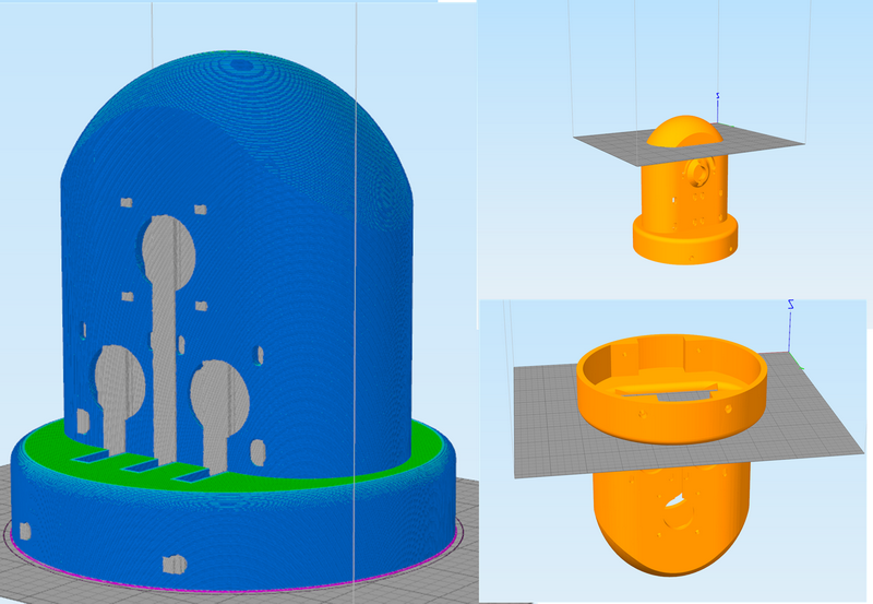
Art1Body is going to be a challenge to print. It originally needed 31 hours to print, but I could bring it down to 19 hours. The biggest reason why it takes so long is the support structure to hold the dome and the lower half flat panel that also needs support structures. Losing the support structure means winning 6 hours.
I am experimenting in Simplify3D to print it in 3 parts. The top halve,
the mid section and the bottom part but upside down. I have chosen the
top part to be printed above the openings that will have mechanical
stress.
I finally printed the bottom part of the modified Art1Body. Note that it is upside down so I avoid support structures. This party is printed in 4h45 (vs 8h if it were to printed the upside way.)
Printing the mid section took me 8h45, and the top section that took 1h30. But when I removed the supports, I broke some thinner walls.
The gluing took challenges and I had to put 10 kg of boxes on top of it to hold it into place. I finally glued the dome on top. It is a Frankenstein model but it only took 13 hours of printing.
The gluing is surprisingly strong. Next will be gluing back the thinner walls.
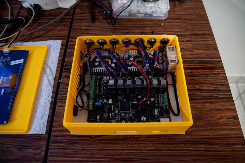
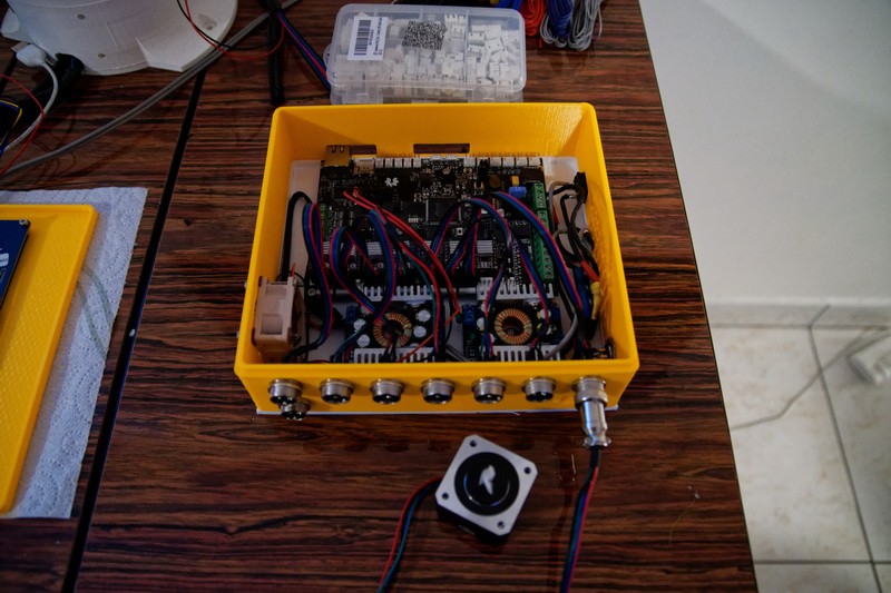
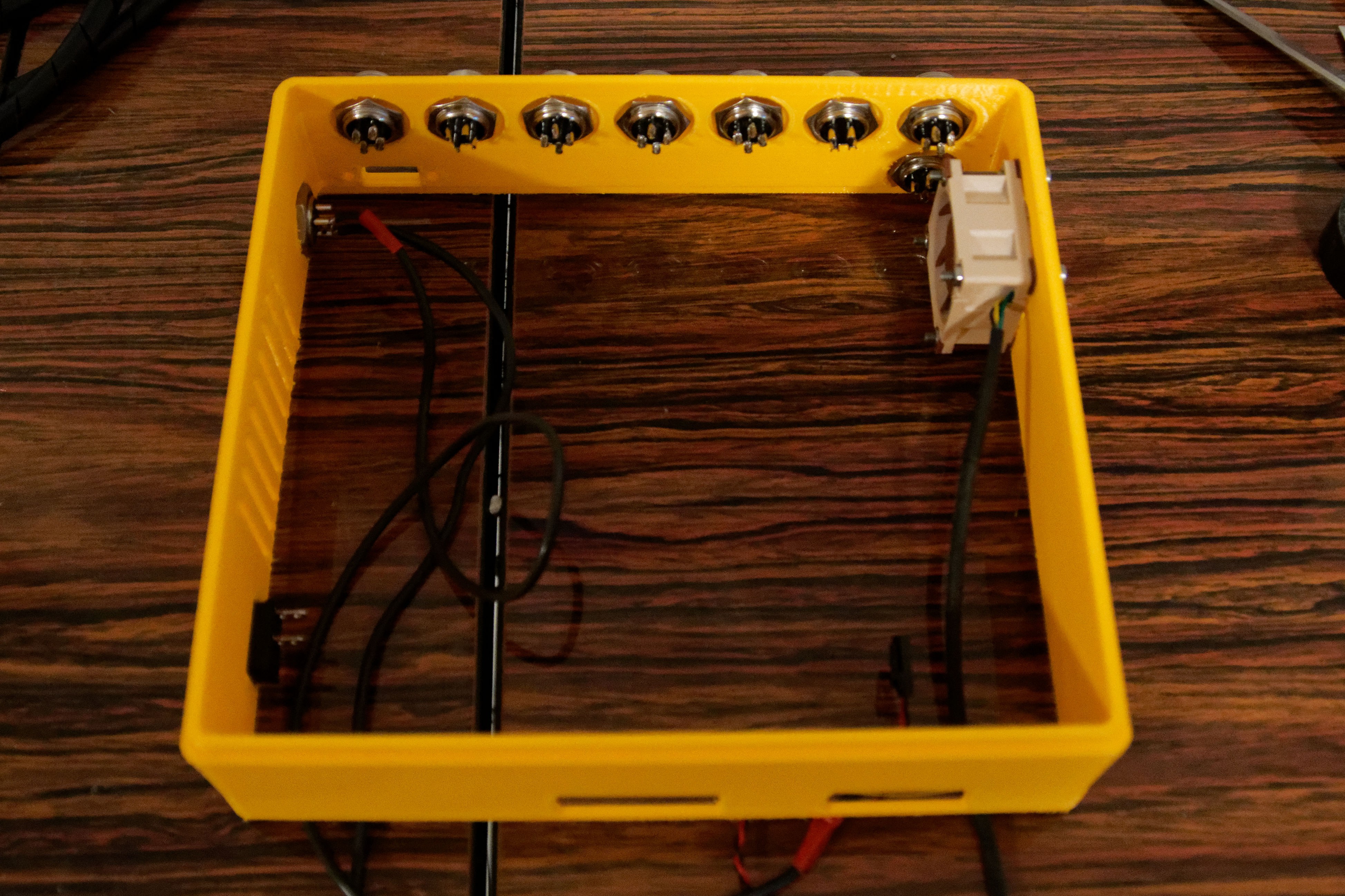
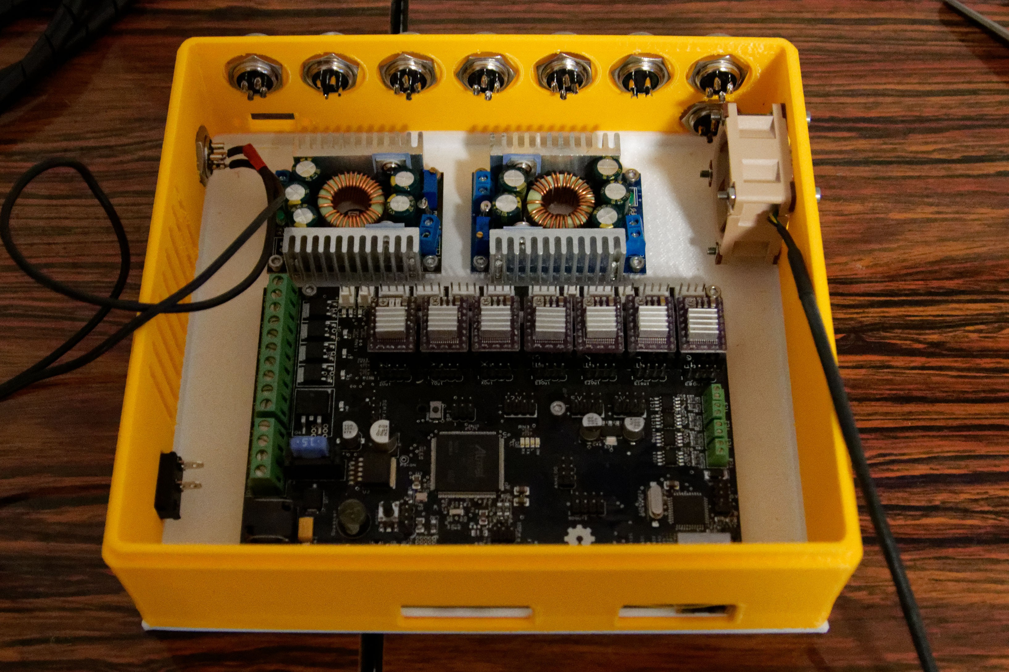
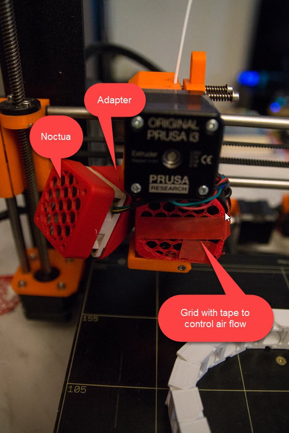
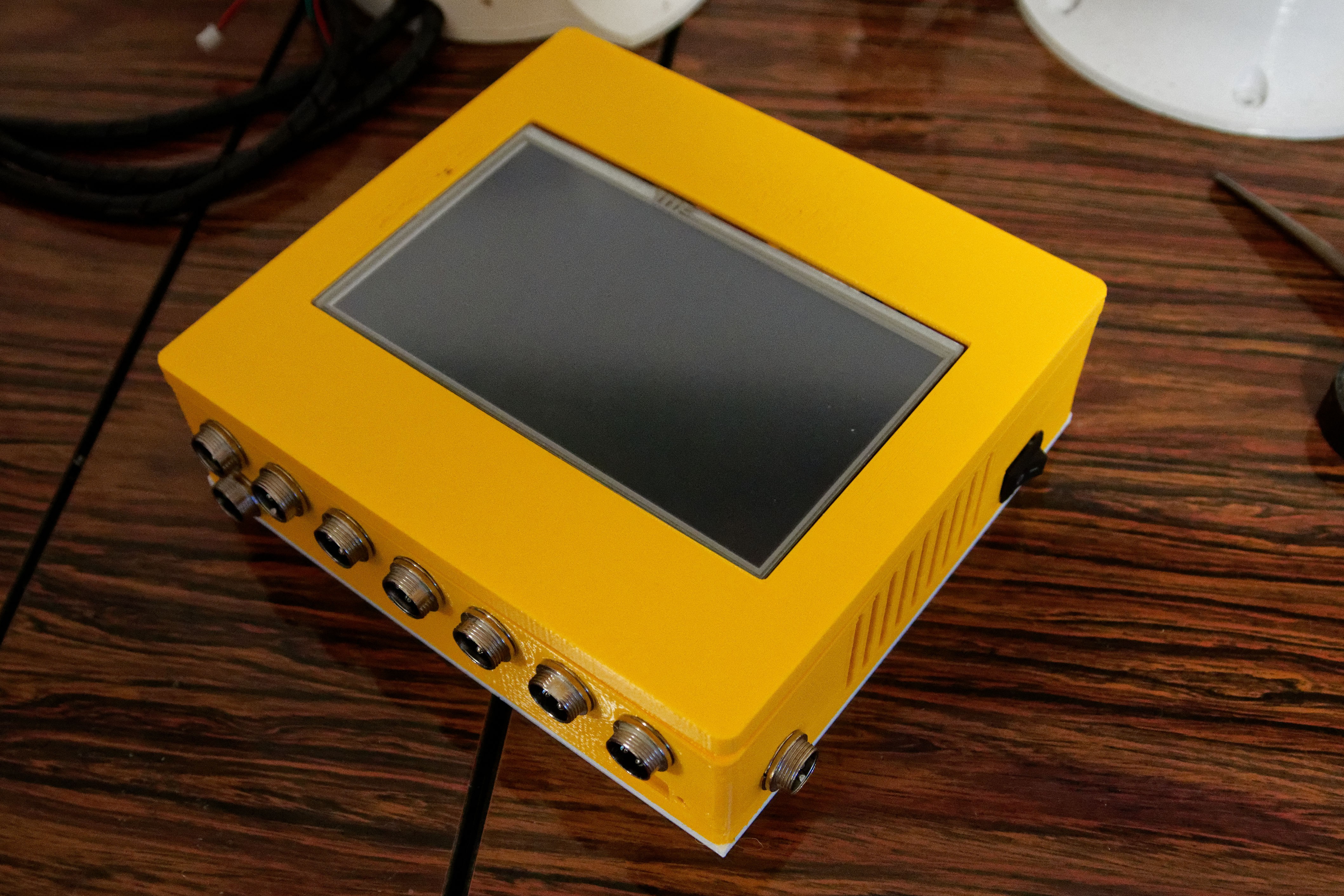 Side view to show the connectors and also the power switch on the box. That power switch cuts off the incoming 24V, so the motor drops out instantly.
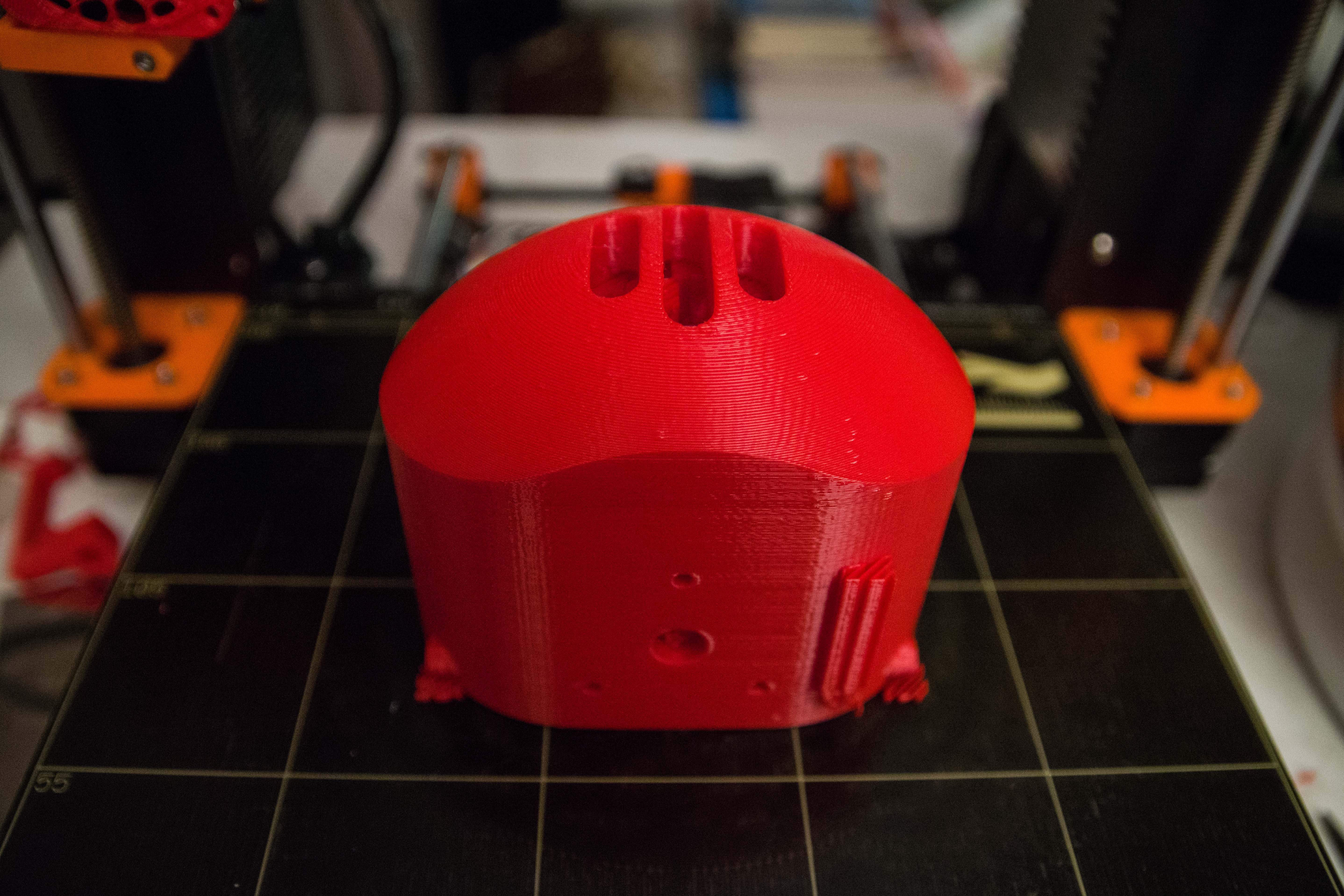

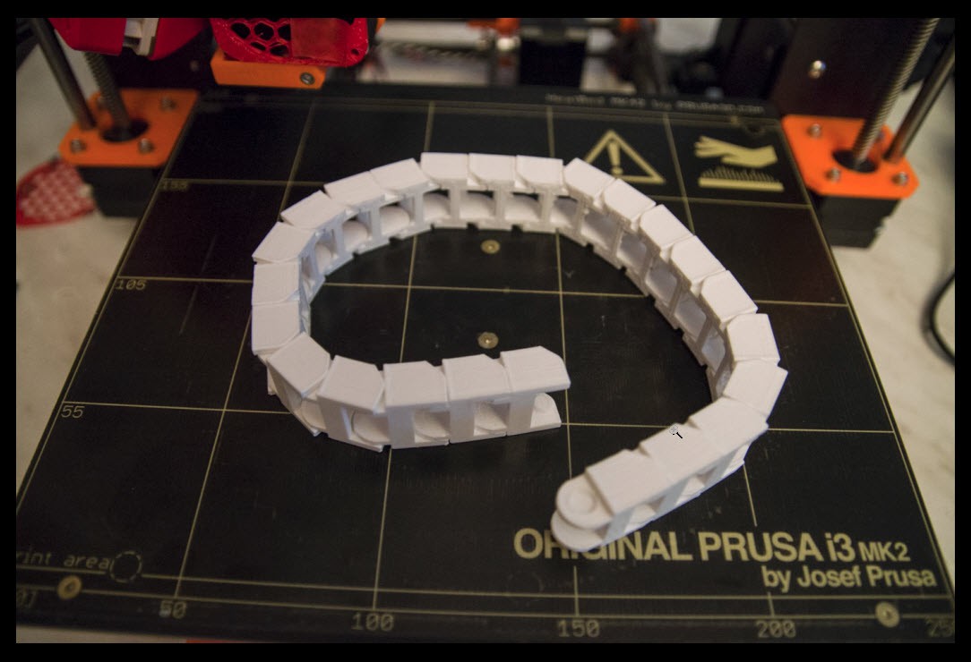 (Assembled cable train)
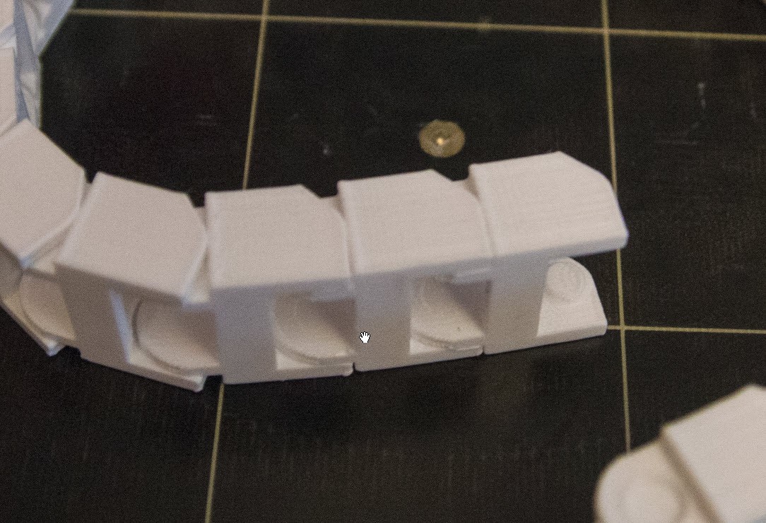


 Aaed Musa
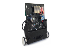
 Ben Steer
 doctek
This is both really impressive because of the skill of the printing and somewhat nail-biting for me to see the gears and so on simply being printed- I think it's going to be a lot better, eventually, to print the body/case of the robot and the suitable structures in it to be able to mount standard off-the-shelf hardware like bearings, gears, and machined parts that are stress-critical.
All of this is impressive, keep it up.