zpekic
There are plenty of great implementations of different and historically important CPUs available on various FPGA-based platforms, but to my knowledge very few trying to implement calculator CPUs. Old calculators where one of the first examples of "microcontrollers" because on the same chip they contained CPU, RAM, ROM and I/O (interface with keyboard and displays). Given that they are a bit different, I thought it would be useful and interesting to describe the design path I took.
The original patent (https://patents.google.com/patent/US3934233 ) explains the guts of the calculator CPU in a very detailed and accurate manner (albeit in a bit of a specific “patentesque” language intellectual property lawyers may be familiar with). However, there are few challenges of using this patent for direct implementation in VHDL:
- 1970s MOS technology is heavy on latches, which doesn’t align too well with FPGAs which are all about clocked registers
- The design had to expanded to include both TI and Sinclair (the originals are distinct and separate chips, each with own mask and ROM contents)
- The original is not microcode driven
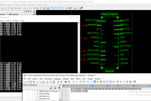
Even so, the end result still somewhat resembles the main components of the original CPU. This project log describes the internals of calculator, as they come together is the main CPU entity implementation file - https://github.com/zpekic/Sys0800/blob/master/TMS0800/tms0800.vhd
Displayunit
The main source of info driving the display unit is the A register. It is however not just a bunch of simple BCD digits that can be directly multiplexed out to the 7 segment + decimal point display because:
- TI and Sinclair have different numeric formats
- Different digit values are used for negative sign
- Error processing is different (Sinclair has essentially none, while TI uses a bit 5 in BFLAG register)
- TI displays the decimal point on the place indicated by value in the LSD of register A, while Sinclair always displays the decimal point in fixed place
- TI has blanking of leading zeroes, Sinclair doesn’t
All of the details above are hidden from the main entity. What comes out is the multiplexed segment (anode) / digits (cathode) output which can drive the display but also the columns of the keyboard. Note that the digits are driven from “digit10” (MSD) to “digit0” (LSD) because that is the only reasonable way to implement leading zero blanking. This is a problem because most of the calculations happen from LSD towards MSD (such as in add/subtract start with 1s then 10s, then 100s etc.).
Rom512x12
There are two of these in the CPU, one containing the TI, another the Sinclair code. During the build time, the appropriate “.asm” file is parsed and loaded as binary content into these ROMs. Note that:
- TMS800 instructions are originally 11-bit wide words. In this design the extra MSB bit is used to indicate a hardware breakpoint (not present in original chips)
- 320 words adds up to 1 256 word ROM + 1 64 bit ROM. In 1975 chip real estate was tight, but on modern FPGAs it is much simpler to “round up” to 512 words
- Both ROMs are driven from the same 9-bit program counter register (“signal pc:…”) and both outputs go into a 2-to-1 12 bit multiplexer as selected by the “Sinclair” input signal
- The “.asm” files are checked in, but they can be re-generated...
Read more »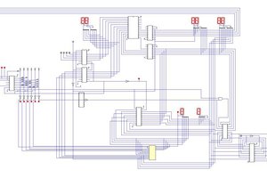
 spudfishScott
 kaimac