Mattias
-
Fixing Slop
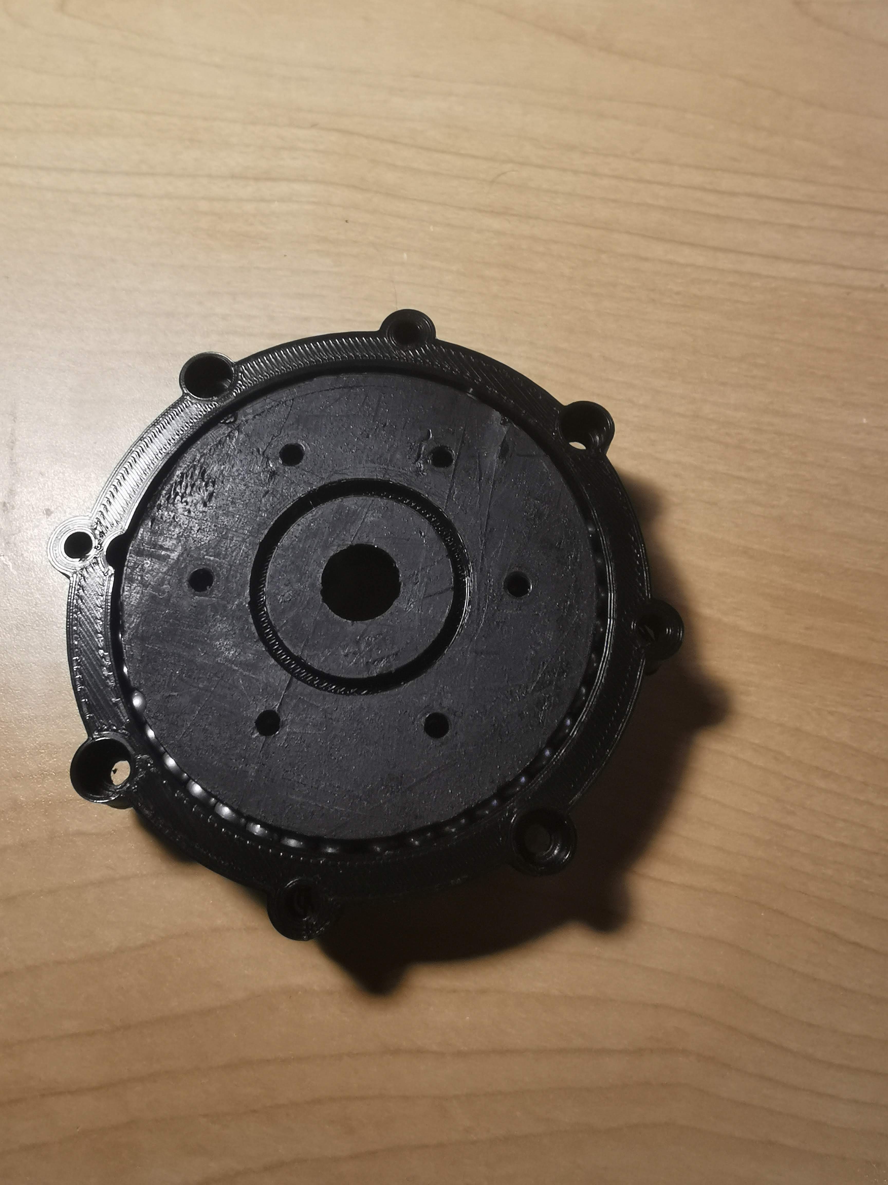
07/05/2020 at 04:06 • 0 commentsThis was a simple fix, just a quick redesign of the actuators to be able to fit a thin section bearing. For context, the original actuator used 4.5 mm metal pellets (from a local hobby store), and a swept cut around the mount plate for the second stage planet gear holder, and the clamp. The assembly for the top portion is as follows:
![]()
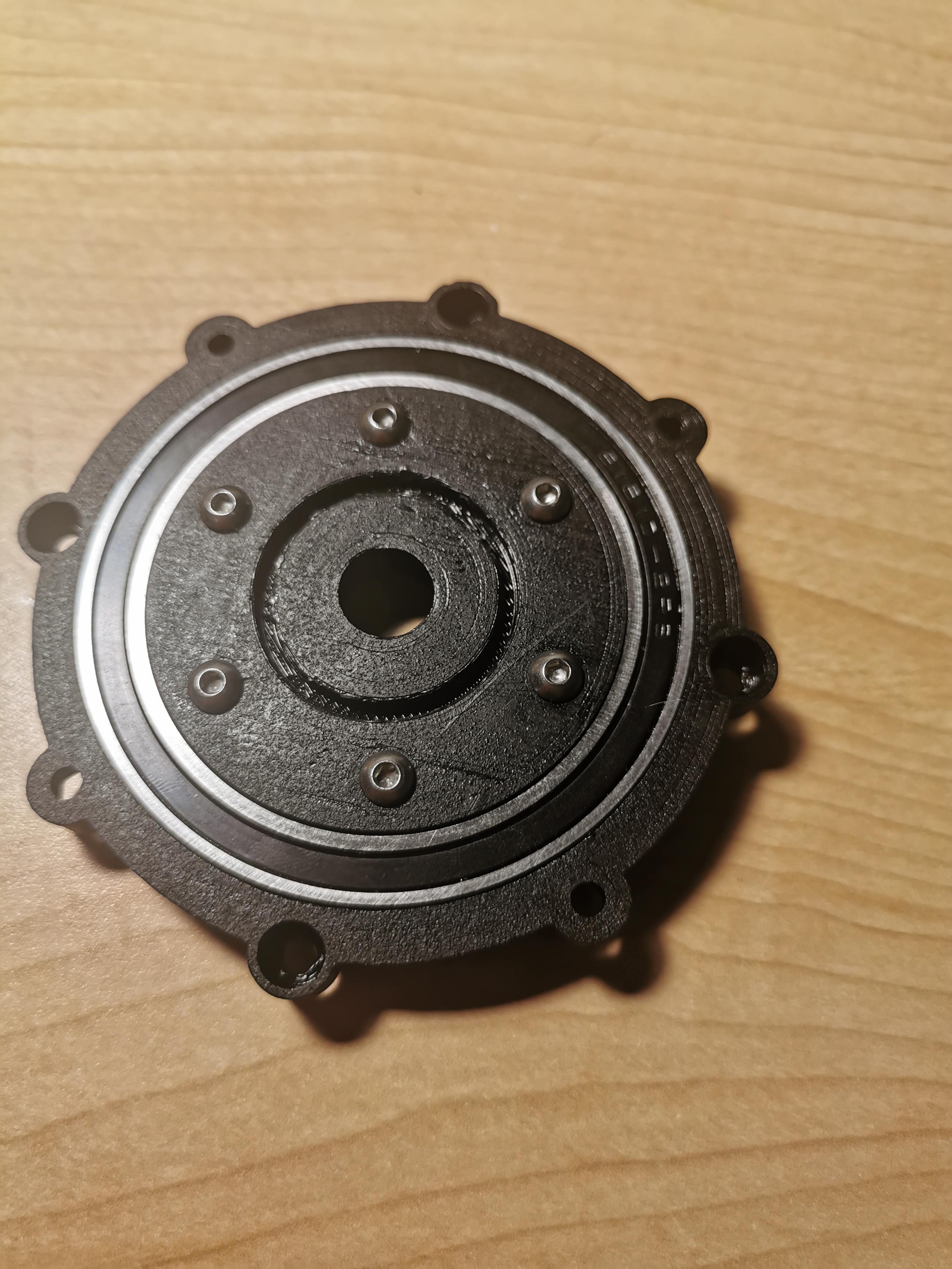
To improve the design I ordered several thin section bearings, 40 x 52 x 7 mm bearings for the small actuator, and 50 x 65 x 7 mm bearings for the large actuators. The .stl files were modified such that it can press-fit the bearings. Below is what the new design looks like:
![]()
-
Control Board Update
06/29/2020 at 05:29 • 0 commentsThe Old Board
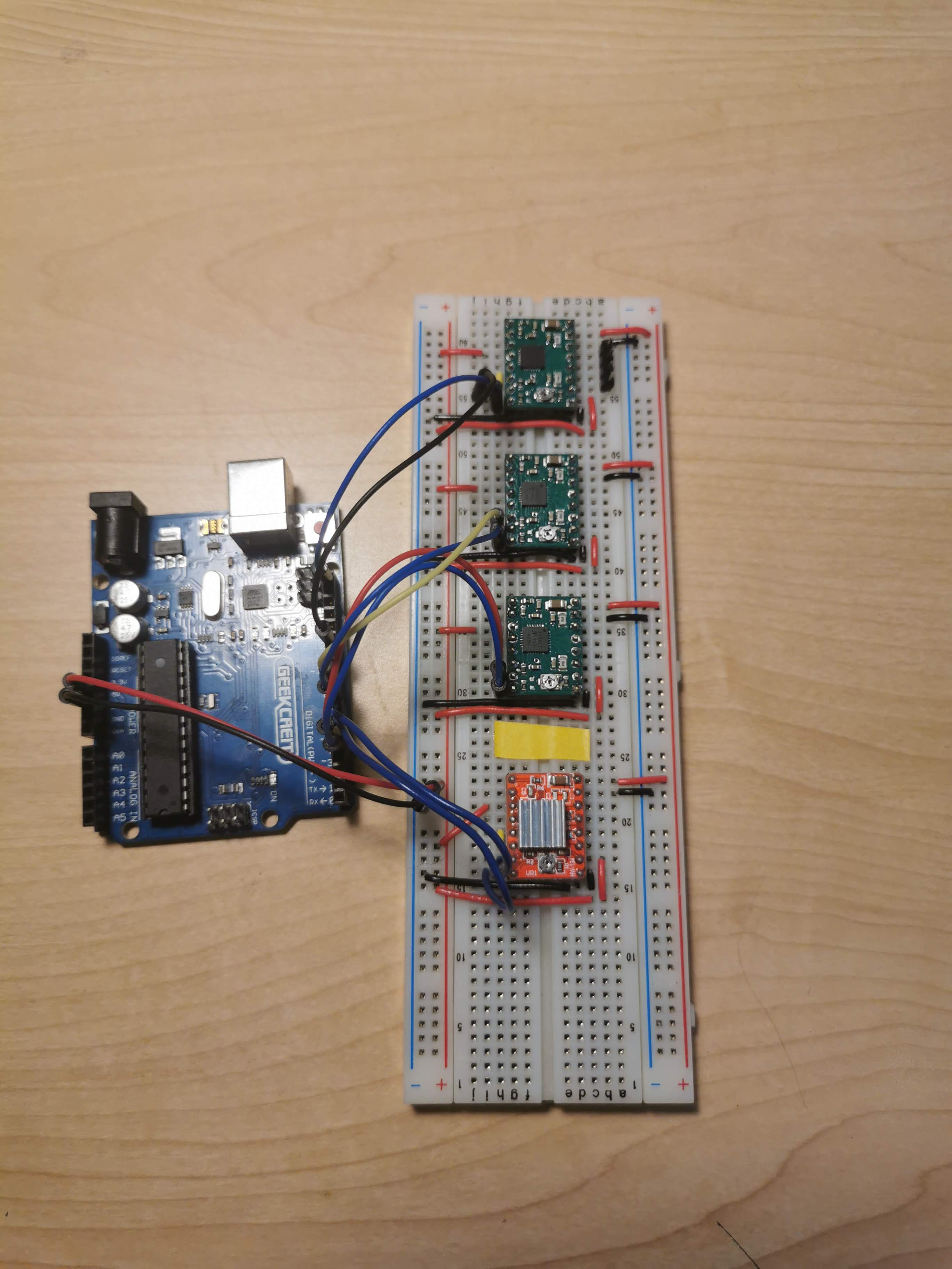
As mentioned, all four joints use NEMA 17 and 11 steppers, which are controlled by four A4988 boards with the 1/4 step pins connected high. When developing the robot these were simply wired up on a bread board as follows:
![]()
This works as needed, however for the custom control box, there needs to be a more compact and elegant solution.
The Longrunner CNC Shiel
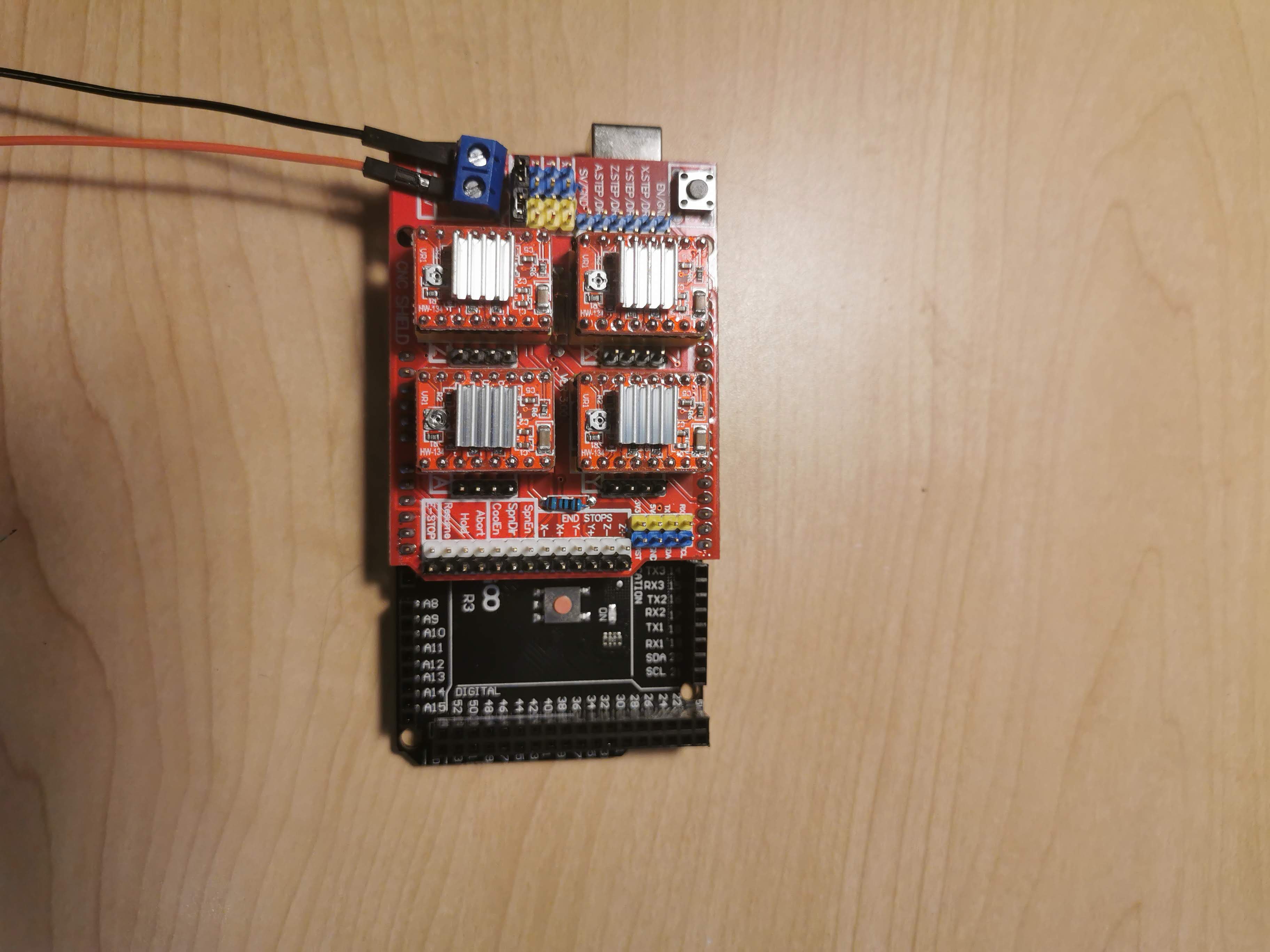
For this the Longrunner CNC shield was used (https://www.amazon.ca/gp/product/B06XJKVLG3/ref=ppx_yo_dt_b_asin_title_o01_s00?ie=UTF8&psc=1). This Arduino shield works perfectly as it has 4 stepper controller inputs (X, Y, Z , made for a 3-axis CNC and an auxiliary clone). To access the fourth axis (labelled A), they connect to digital pins 12 and 13 on the Arduino for step and direction. I also purchased an Arduino Mega to accommodate the larger sketch sizes required by the ros_serial library to interface with the MoveIt publisher (coming next). Here is the new circuit:
![]()
-
Testing ROS, MoveIt and RViz
06/26/2020 at 03:44 • 0 commentsQuick Recap
For the past few days I have been figuring out the ROS environment. I decided to use ROS as the primary ecosystem for the robot in order to take advantage of MoveIt and RViz. Before, the robot ran off a custom controller, inverse kinematics model, and a basic command line based interface as a way to enter the desired cartesian coordinates. This worked perfectly for testing purposes and many parts of the code will be reused such as the joint interpolated motion functions, however with MoveIt it will be a much better visual way of controlling the robot poses and position. Along with this, ROS is very reusable and modular and concepts can be applied to future robotics projects.
Planning
With this I plan to write an Arduino program using the rosserial library that subscribes to the MoveIt topic (/joint_space). This will let the Arduino know the joint angles and pass them to the joint interpolated motion program that I previously wrote (can be found in the GitHub repo) - a seamless integration. This portion is not yet written, however it will be in the coming days. Here is a screen cap of some test motions in RViz.
-
First Coordinated Movements - Joint Interpolated Motion
06/23/2020 at 22:03 • 0 commentsOld: Slew Motion
The last few days I have been finding a way to make the robot travel in fluid movements. Before I was using simple slew motion for controlling each joints, meaning that after the inverse kinematics (IK) computes the desired joint angles, it would send those angles to each motor and run them all at their max speed. This works however it creates a jerky looking motion path from the end effectors perspective.
New: Joint Interpolated Motion
After doing some research, I found that joint interpolated motion would be a better approach (the following reading helped me understand the implementation: https://www2.isye.gatech.edu/~czhou/MotionTypes.pdf). It works by making all joints of the robot start and stop at the same time. This causes the end effector to follow a smoother path, not a straight line, but more circular in nature. In practice, the controller will get the joint configuration from the IK model, then we will find which joint will travel the farthest distance - since the maximum speed of each joint is known, the longest time for each joint can be found as well:
maxIndex = findMaximum(jointTimes, JOINT_SPACE);
maxTime  = jointTimes[maxIndex];
Now with the maximum time, the new velocity of the other joints can be found since the distance traveled is known from the IK. The full code can be found in the code repo for this in the motors.h file. (https://github.com/mAzurkovic/robotic-arm/blob/master/src/input_program.c/motors.h).
Demonstration
Here is a demo of the implemented joint interpolation controller running to a few coordinates:
As it can be seen there are still a few issues - the main one being the joint with the longest distance to travel does not stop at the same time as the rest of the joints. This is currently believed to be a mechanical issue.
3D Printable Robotic Arm - ARManda
This is a 4 DOF 3D printable robotic arm that I am currently developing.