rOzzy87
-
Inventory usage
02/04/2021 at 21:00 • 0 commentsThe PCB design phase has ended, and I finally ordered a batch of 5 pieces. This is the lowest amount I could get, even though a single board's footprint is way bigger than most of cheap PCB orders in total. (I'm thinking an average 5$, let's say 10 pieces of 40mm by 80mm board from JLC)
So I'll have 5 boards, from which at most I need 2. The others? Well I have one friend who is willling to support me by taking one off my hands, but he wouldn't want a full size keyboard. Ideally he would like a 75% layout but that is fundamentally different from a full size. So I came to an agreement with him having a tenkeyless layout. You know: the almost full size, without a numpad.
Now this posed a new problem: I had to design the layout in a way so that the numpad is not in any way necessary for the PCB to function. By function, I mean the LEDs are working as intended. And then it hit me: why stop here? There is a layout referred to as 60% which is just the alphanumeric part of a full sized keyboard. So in this spirit I routed the backlight LEDs' traces in a way that you can snap off the numpad, arrow key section, and the function row as well to incorporate 4 separate layouts in one PCB. Neat!

This is the back side of the PCB. As you can see it marked on the silkscreen, it can be cut along the lines to get different layouts (and perhaps make your very own separate numpad for your 60% layout. 
It's a bit harder to realize, but the front of the PCB contains the traces for the backlight, which is routed from the position of the right Ctrl button, in a way that if you cut off the numpad, or the arrow section, or the function row, you still have one continuous trace for teh LEDs In the end I've decided to try and utilize all the boards in different ways:
- My friend gets one. He'll decide if he is using all of it, or just the TKL layout. Most likely it'll be a wired TKL with RGB and maybe a built-in USB hub.
- One full size wireless for my media and game focused PC, connected to the TV. I'll use the Logitech K270 donor for this one. Referred to in the future as "the K270"
- One full size wireless for work. As latency is not a real concern I'll use an ESP32 with the BLE HID library. Addressable RGB. Nickname: "the ESP32" Yea, I need to work on my creativity...
- One TKL, and a numpad. Yes, separately. Just for kicks. By this time, I'll have some experience and decide if this will be wireless or not.
- If I don't mess up any of the previous ones, I'll have the last board as an ultra compact 60%. I don't see this happening yet, LOL.
The last two is seemingly so far in the future that I don't even plan any other details about them as of now.
The K270
Since this will be the most annoying - mainly because of the huge amount of hand wiring over the PCB - this will be the first I'll try to make. The K270 has 8 media keys that won't be present in the mechanical version. At least not in the standard form... You see, the K270 only has one status LED for the Caps lock, so the area with the status LEDs will be almost empty. I was thinking this calls for a rotary encoder! I could use the LED on the left side and I have a place on the right for the encoder. I could make a cute little knob to control the volume, and also use the encoders built in button to mute/unmute.
The problem with this however is that the encoder is not really electrically compatible with a the K270's board. So I will need a control circuit that imitates a switch being pressed. Maybe an Arduino Nano with some deep sleep to not consume too much battery power. It could sense the encoder movements, and trigger a transistor for e.g. 100 ms for each impulse.
The second reason I would use a Nano instead of an ATTiny85 is that I would like to monitor the user interactions. If 5 minutes pass without any keypresses, I could switch off the backlight and switch it on after registering a keypress. I could also use an analog readout on an LDR to determine if the backlight is even needed or not.
For the backlight, I need to see how much power the WS2812s are consuming, that will decide if I'll use these or some standard LEDs. Maybe I'll start by soldering the neopixels on one of the PCBs, and measure much battery life could I achieve. If I'm not satisfied, I'll use another PCB for this one, and keep the one with the neopixels for a wired project.
Battery management-wise I'm planning to use a cheap chinese LiPo charger module, and maybe a boost converter for the arduino. I don't know if the latter would be necessary or not. Battery charging would be possible via an exposed USB type-C connector. There will be a separate master-power switch to turn off the whole thing. I would power the K270 receiver directly from the battery, maybe with some low dropout regulator to maximize the voltage at 3V. If it turns out that I need to use simple LEDs for backlight, I'll need another boost converter to stay efficient.
Mechanically I will go by hot swap sockets without a plate. Considering hot swap sockets are not really meant to inhibit plateless designs, I'm prepared to see some sloppy switches, as the holding power of the sockets alone will not be enough. In that case, I'll be on the search for some FDM printed plates. Or laser-cut. We'll see. I can always switch to another PCB if neither works out.
The ESP32
Since this is a scratch build, I'm not limited in any way, hooray! Well, except for the microcontroller pin count that is. the ESP32 has a lot of pins, but some of them are not recommended to use in some circumstances. See here. It has basically 23 pins you can use with minor restrictions. Well, my full size layout matrix has 21 columns. this won't work.
Enter the shift register. We only need to scan a single column at a time, and we always need to step to the next column whatever happens right? This is perfect! 3 pieces of 74HC595 chips daisy chained and we have 24 columns to scan! I just need to make a convenient PCB to fit next to the ESP, one pin each for clock, data, and reset, that means we still have 20 pins to read the rows, control the backlight, and whatever other devices I might add.
Speaking of the devices, I would really like to try a 0.91" OLED display next to an Xbox thumbstick, but to be honest, I didn't really find a real use for a display on a keyboard. For the thumbstick I thought I could emulate a mouse with it, and use the built in button as a left click. (maybe hold for a right click?)
Backlight, Battery management, and mechanical design would be the same as the K270. The ESP32 boards have an AMS1117 3.3V regulator built in.
The others
Not decided yet. Really. If everything works out fine, I will spend a better part of 3 months working on the first two projects 1-2 hours a day after work. We'll see.
-
PCB design decisions: Other stuff
01/28/2021 at 19:28 • 0 commentsThere are a few thigs I didn't mention yet. Mainly because there is not much logical thinking in these ideas, simply creative brainfarts. Or copies of others' ideas...
Unconventional components
Most of the wired keyboards have 3 status LEDs in the upper right corner, however, most of the wireless keyboards do not. this leaves that upper right corner empty. I had to come up with ideas what I should fill it up with. Having the option to install the 3 status LEDs that is.
Right now I have support for I2C OLED displays in 2 sizes: a 128x32 0.91" and a 128x64 0.96" variant.
I also thought about some input devices as well. this way I ensured there are footprints supporting the common EC11 encoder and the XBOX thumbstick, although it is not clear yet if the latter will fit physically
![]()
Hardware structure
One of the main concerns of mine regarding the hardware assembly is the machining of a plate. The preferably metal sheet isolating the PCB from the outside world. You pop the switches in there and connect the to the PCB all at once. From the on, the plate is connecting the switches structurally, and the PCB eletrically.
This is not the way I'm planning to do it. Mainly because the plate has to be precise, otherwise the keycaps will show every imperfection amplified. That would suggest a CNC routing process, which I cannot do myself, and would be very expensive to have someone else do it.
Instead, my plan is to form a case which will cover the parts of the PCB not covered by the keycaps, and the switches would be held in place by the PCB itself.
BUT... I would keep the possibility of using hotswap sockets as well. the end result is a footprint which is by default a solder mount. However, if we drill the holes for the switches' legs with a 3mm drill, we can solder in the kailh-style hot swap sockets. Great!
![]()
-
PCB design decisions: Backlight
01/26/2021 at 21:24 • 0 commentsI'm not really a fan for RGB, in the {something}-puking-rainbows way, so my first thought was to use single color LEDs. This means I need to create some steady current through a resistor for each N pieces of LEDs. If you want to drive 105 LEDs from a battery, you need to minimize the power lost on the resistors, and limit the current quite a bit.
Plain battery driven LEDs
I was thinking 1 - 2 mA for each LED that would mean 105 - 300 mA which, when drawn from a single cell 3000 mAh tablet battery, would last 10 hours. But let's calculate power:
A single red LED has a forward voltage of about 2V. This means that in a single LED per resistor would consume
but the resistor consumes
This means about 54% of efficiency, tons of energy loss to the current limiting resistors. That's terrible to use in a battery powered application. Not only that, but the LED brightness in this context would significally vary with the battery draining over time. Since 3.7V is just the nominal voltage, and the real value will be somewhere within the 4.2-2.9V range.
Boosting voltage
However. If I stabilize the voltage with a simple boost converter module, how would it work?
Let's take the LED from teh previous example. 2V forward voltage driven with 1mA of current. If I boost the voltage to 12V, I could use 5 LEDs in series and a single resistor. This way the LEDs use
and the resistor would consume
This is way better, at around 83%. However, boosting the voltage comes at a price, which is the 80% of efficiency with the cheap chinese modules I'm planning to use. That means the total power consumed by the 5 LEDs and the resistor would be about 14.4mW which will result in the efficiency range of about 67%. That's less optimal, but still better!
As you can see the main source of power loss is the resistor. Lowering the power consumed by the resistor means raising the efficiency. As one can see, the power is driven by two factors: Voltage and current. As for the current we can't do much, we need to provide 1mA to the LEDs. So the only option is to lower the voltage dropped on the resistor compared to the supply voltage.
And yes, if we drop the voltage to 11V, the resistor will now only drop 1V, consume 1mW, lowering the total consumption to 11mW.
This is a figure of 91% efficiency before, and 73% after adjusting for the boost converter. Not good, but way better than the 54% we began with.NeoPixels maybe?
One great feature of the WS2812 smart LEDs is that they have integrated LED drivers. This means, that this whole efficiency thing and the resistor stuff is not my F-type problem anymore. Or at least I have an excuse why my design is crap. All it needs is a 5V boost and a bypass cap, but I guess you can just leave the cap out and it would still work fine.
Concluision
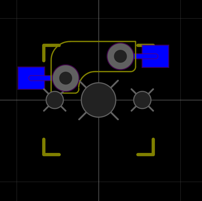
Conclusion? There is none. I'm trying to design a PCB where all these are possible. Single LED per resistor, multiple LEDs per resistor, and WS2812. We'll see which one works. How would I achieve this? Take a look:

This footprint can be used with 3mm LEDs, 3528 SMD LEDs, and WS2812s as well. For standard LEDs we can use one, or several LEDs per resistor. -
PCB design decisions: Key matrix
01/26/2021 at 19:52 • 0 commentsSo I began to design a PCB. However, I soon found out that manufacturing PCBs this size is a costly process, and the minimum amount of boards I could get is 5. This means I will mess up one (trust me, this is why I order arduinos in pairs as well), and have 4 on hand to build. And who wants 4 identical ones, right? So the decision was to accomodate a few ideas.
Starting with the control circuit. I decided to sacrifice my Logitech K270 and use its control board in one of the keyboards. This means Logitech's custom key matrix. This means a hot mess of wires that don't even look like a matrix. If I accomodate that into the PCB that means I have to stick to that whatever controller I'm using for the other ones.

The Logitech K270's key matrix... rows? columns? Let's say it's dimension no 1. So I decided to go with a default rectangular matrix instead. Ok, but then I need to somehow connect the K270 PCB anyway....
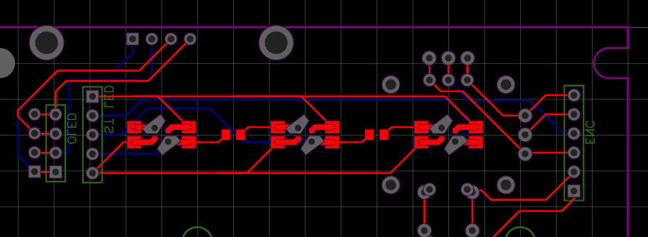
The solution: Use those fancy 0R "resistors" in the design! Between each switch that would otherwise be connected, I left some pads so one could either connect them with a solder bridge or leave them alone and create a custom matrix, like the K270 has.

The pads in the white brackets would be shorted with solder bridges when I need a "normal" key matrix. If I need to reproduce some proprietary matrix, I'll just use hand wiring and leave these open. As you can see, the row tracks fit through the columns' pads, thus enabling a single sided matrix. We'll talk about the irregular shaped pads in another post. Even better: this way I could use one side of the PCB only for the key matrix, since you can pass the column's track between the pads of the rows' bridges.
So the end result is that basically for the K270 the PCB will only serve as a mechanical piece holding the switches and LEDs in place. I'll need to hand wire the martrix myself. For other builds however, I will only need to hand wire the columns and rows to the microcontroller board.
RKey
My very own ISO mechanical keyboard. Custom PCB with many options and features.