 P
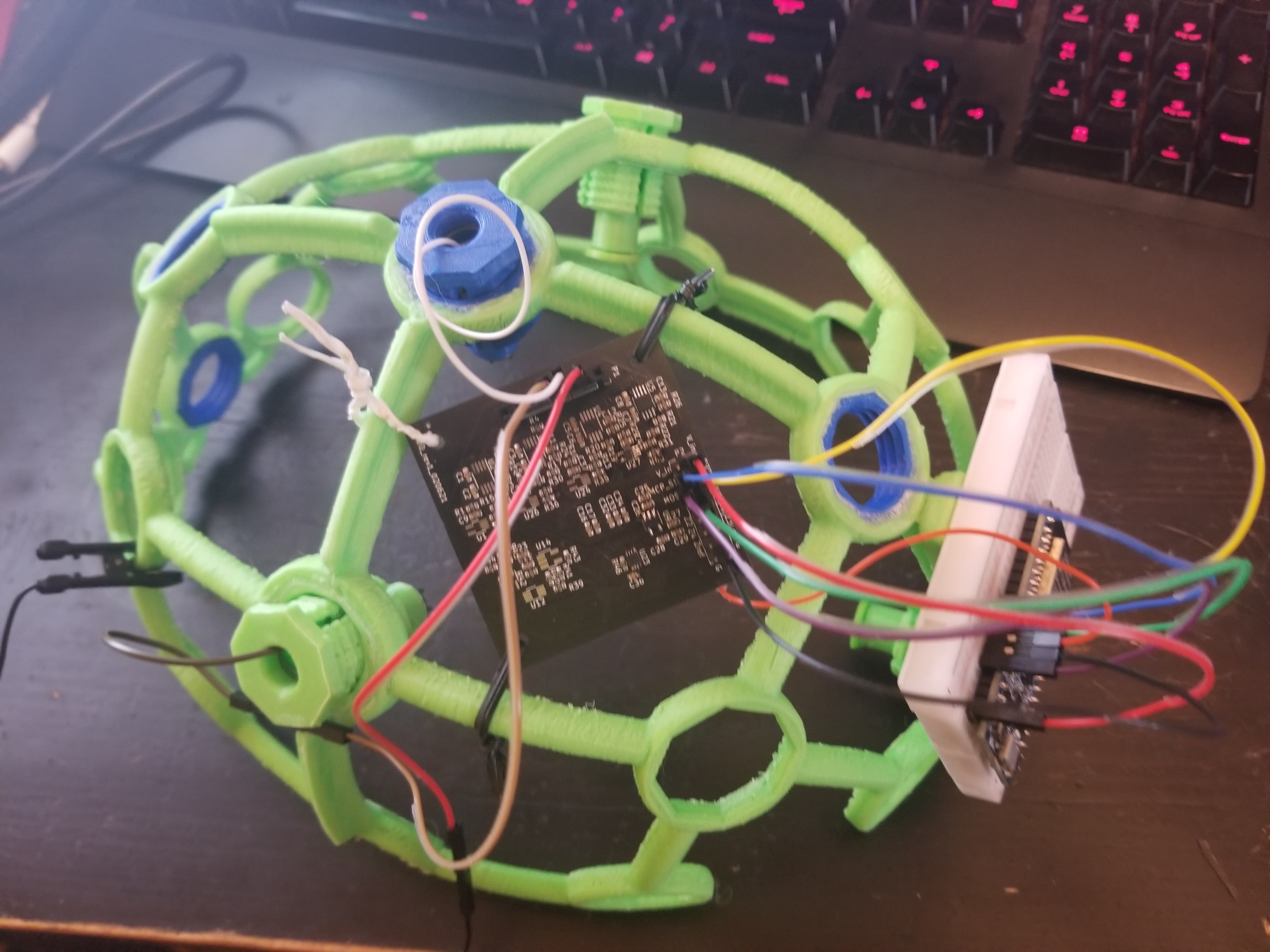
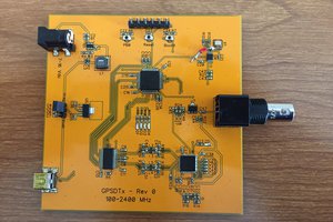
PI basically copied the Ganglion design, but removed the SD card holder, accelerometer, and the obsolete bluetooth/microcontroller module. I also hard wired all the instrumentation inverting inputs to the reference voltage since I only plan to do single-ended sensing. I was able to squeeze everything in to a pretty tight 2-layer board. I haven't worked out the math yet but at ~$2 per board (including shipping), 4 instrumentation amp ICs and a few other $2-$3 ICs, and the main AFE chip (MCP3912) the whole thing comes out to be probably $20-$30 bucks, so easily in most people's budgets.
0%
0%
ESP32 EEG
Heavily inspired by OpenBCI, especially their ganglion board design, but with an ESP32 handling communication/control
Become a Hackaday.io member
Already have an account? Log in.
Just one more thing
To make the experience fit your profile, pick a username and tell us what interests you.
Pick an awesome username
hackaday.io/
Your profile's URL: hackaday.io/username. Max 25 alphanumeric characters.
Pick a few interests
Projects that share your interests
People that share your interests
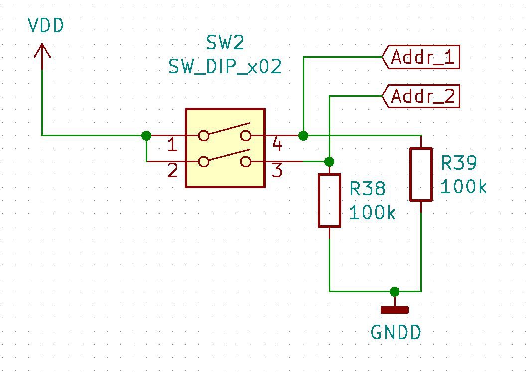
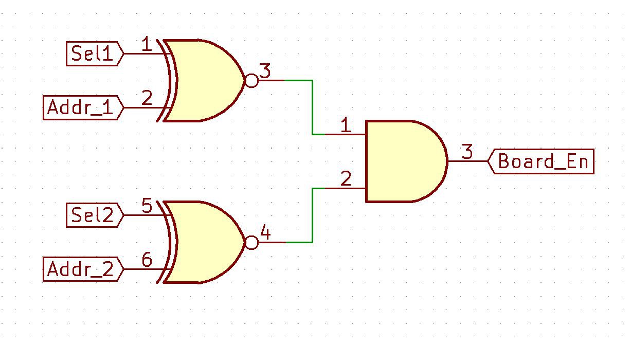
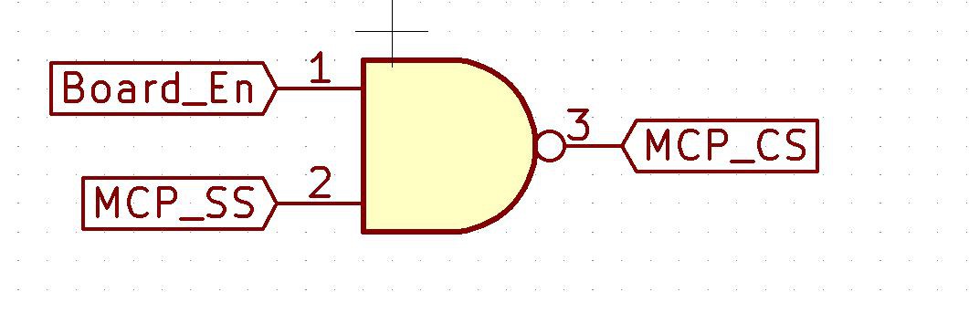
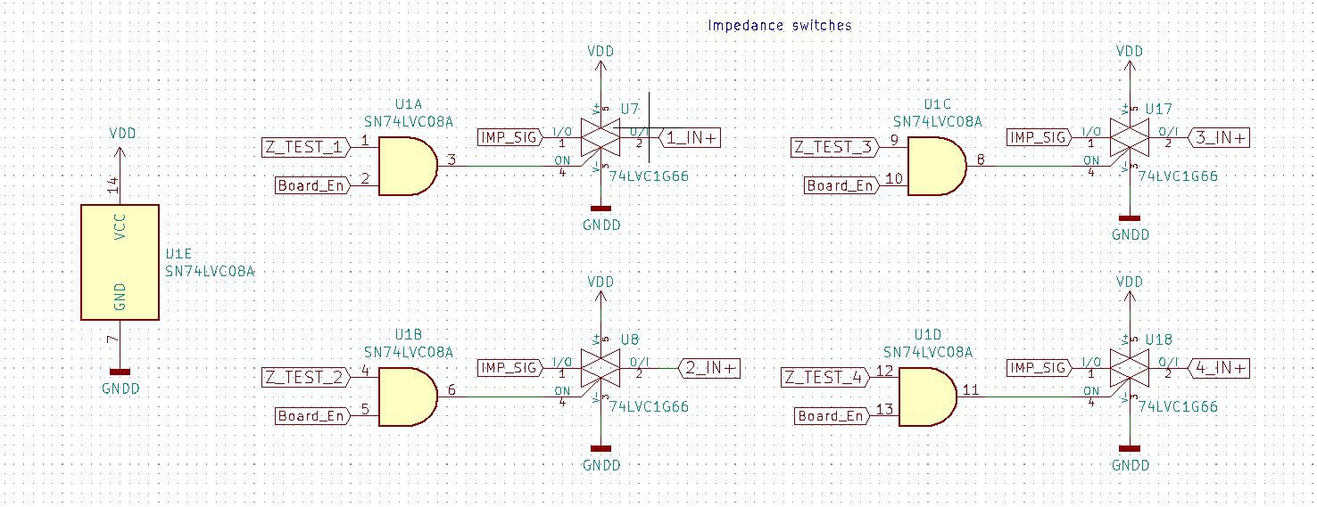
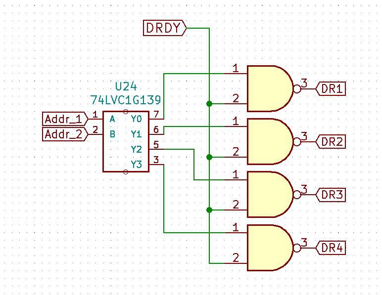 But with those small changes I should be able to then stack the boards and use just 2 address lines to enable the proper board for sampling or impedance measurement. So instead of needing 16 (impedance switches) + 4 (MCP_SSs) + 3 (MISO/MOSI/SCK) = 23 GPIOs, I can get away with just 2 (select lines) + 4 (impedance switches) + 1 (MCP_SS) + 3 (MISO/MOSI/SCK) = 10 GPIOs.


 Taylor Schweizer
 Bharbour
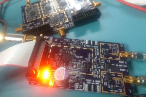
 Jon Klein
Hi, I am very interested in this project.
I am still a beginner, but I immediately placed a foundation order with KiCAD data for 2021. So I have a question.
I see that the project log currently stops posting in April 2021.
I would like to know more about the reasons for abandonmen or if there is any history that has not led to continued log.
Thanks for sharing this great project.