 land-boards.com
Video Series
The video series refactors the CPU from scratch and documents the details along the way. Running on an inexpensive FPGA card.
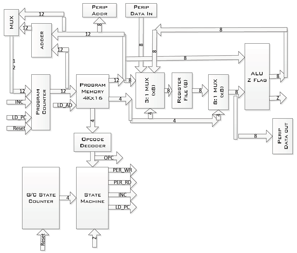
IOP16B - I/O Processor with minimal instruction set
- Useful for offloading polled I/O or replacing CPUs in small applications
- Coded in VHDL
- Runs at 50 MHz / 4 clocks = 12.5 MIPs
- Small size in FPGA
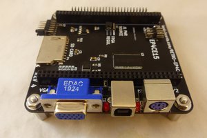
- Uses 226 logic cells in an Altera EP4CE15
- Minimum 2 of 1K SRAM blocks (depends on program size)
- Trade-off - SRAM could be replaced with logic cells (in theory)
- 16-bit instruction size
- Simple/consistent fields
- 4-bit opcode
- 4-bit register field (shared with address/offset)
- 8-bit constant (shared with address/offset)
- 12-bits of address / program memory
- Allows for up to 4096 instructions in the program
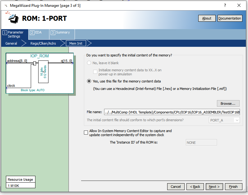
- Program is stored in FPGA ROM
- Set size of program memory in INST_SRAM_SIZE_PASS generic
- Up to 4KW of program size (12-bit address)
- 8 registers in Register File
- 8-bit registers (read/write)
- Used for parameters/data (allocations below)
- Reserved space in instruction for up to 16 of 8-bit registers
- Peripheral bus
- 8-bit address (controls up to 256 peripherals)
- 8-bit data
- Read strobe (a couple of clocks wide)
- Write strobe (a couple of clocks wide)
Block Diagram
Opcodes
Capacity for 2 more instructions
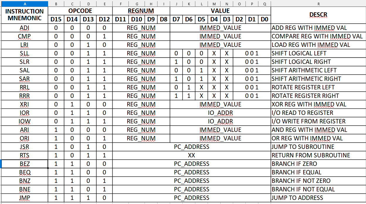
- ADI - x0 - Add immediate value to register
- CMP - x1 - Compare register to immediate value
- LRI - x2 - Load register with immediate value
- Shift/Rotates - x3 - Shift/Rotate, Left/Right, Arithmetic/Logical
- XRI - x4 - Exclusive OR register with immediate value
- RSV1 - x5 - Unused, reserved for expansion
- IOR - x6 - I/O Read into register
- IOW - x7 - I/O Write from register
- ARI - x8 - AND register with Immediate value and store back into register
- ORI - x9 - OR register with Immediate value and store back into register
- JSR - xA - Jump to subroutine (stack depth can be 1 or 16, set in STACK_DEPTH generic)
- RTS - xB - Return from subroutine
- BEZ - xC - Branch by offset if equal to zero
- BNZ - xD - Branch by offset if not equal to zero
- JMP - xE - Jump to address (12-bits)
- RSV2 - xF - Unused, reserved for expansion
Fields
- d15..d12 = opcode
- d11..d0 = 12-bit offset (BEZ, BNZ)
- d11..d0 = 12-bit address (JMP)
- d7..d0 = 8-bit address (IOR, IOW)
- d11..d8 = register number (LRI, IOR, IOW, ARI, ORI)
- d7..d0 = Immediate value (LRI, ARI, ORI)
Stack
The stack determines whether subroutines are supported (JSR/RTS instructions). Sizes are:
- 0 - No stack / no subroutine calls
- 1 - Single level of subroutines
- No nested subroutines
- N>1 - 2^N deep
- Supports deep nesting
- Consumes 1 memory block
Registers
- Reg0-Reg7 - Read/Write values
- Reg8 - Hard coded to x00
- Reg9 - Hard coded to x01
- RegA-RegE - Not used (read returns x00)
- RegF - Hard coded to xFF
Assembler
Assembler is written in Python (Python 3),
CSV file driven. Header is defined as:
['LABEL', 'OPCODE', 'REG_LABEL', 'OFFSET_ADDR', 'COMMENT']
 Tim Ryan
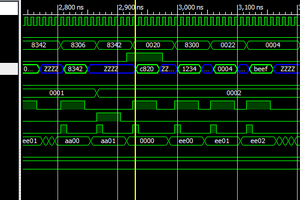
 Erik Piehl