Something I've known about for perhaps a week are these FSLPs:
These are the only ones I can find, which are allegedly 100 x 10mm, though the black film certainly looks a lot wider than 10mm.
Today, I've found out that there is a thin-film style of potentiometer, and it seems only one manufacturer makes it commercially:
The ThinPot, a narrower version of the SoftPot.
I also assume that, unlike FSRs and the aforementioned FSLP, it's not cuttable.
Below, I found some videos of people layering these pots ontop of an FSR:
While I think it would be nice to be able to just touch anywhere on the belt and Tetrinsic can sense exactly where, I see it as an added luxury considering that the price would be a considerable percentage of the BOM and the position in day-to-day use is already acquired via the magnetic encoder on a motor.
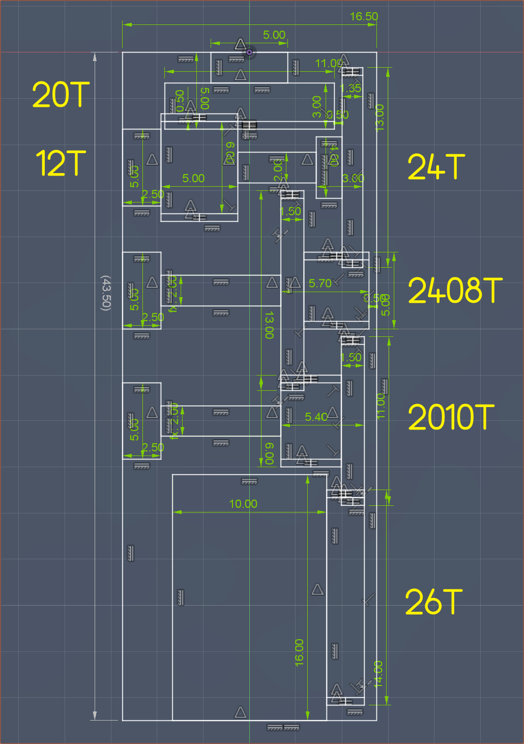
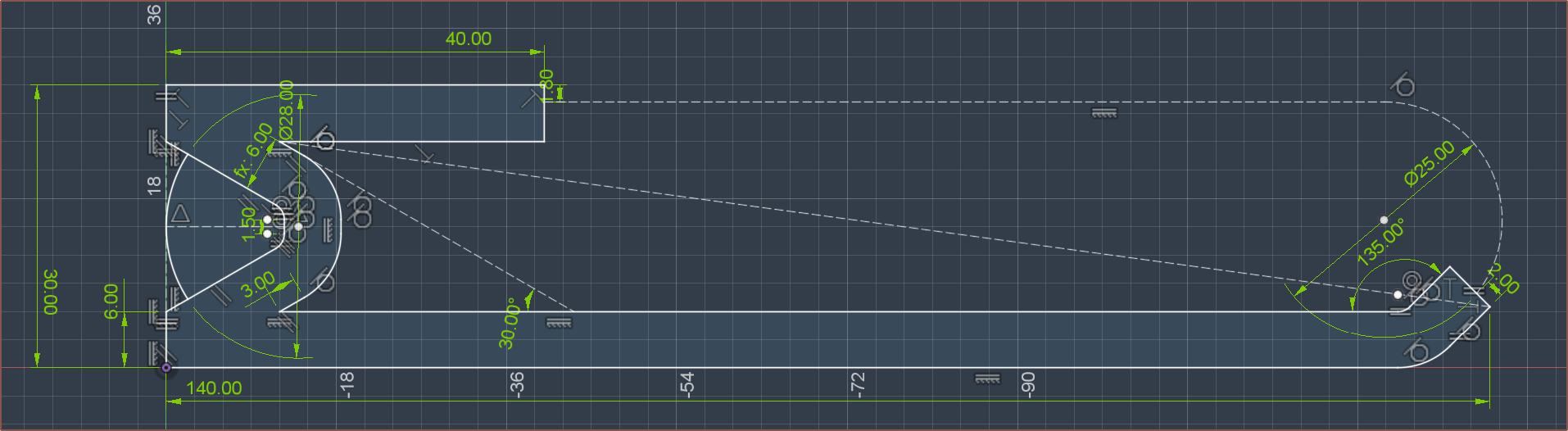
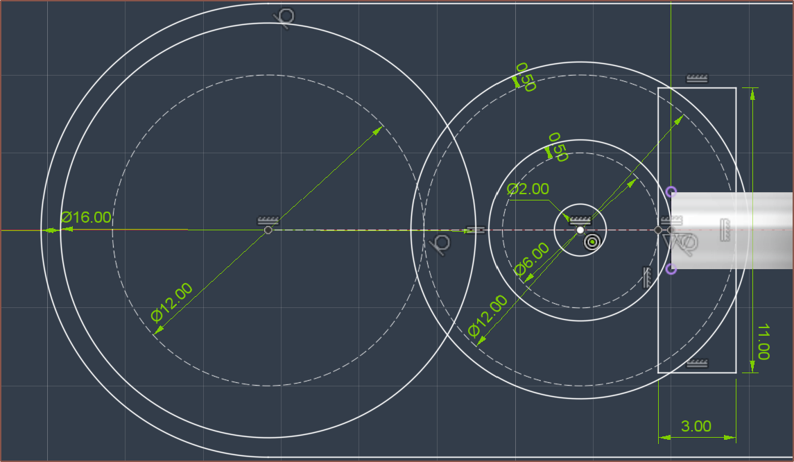
The new gearing strategy (including the 16mm pulley). It's 45mm end-to-end. Everything has at least 0.5mm tolerance for non-meshing locations.
The gear reductions blend the domains of Tetrinsic and Tetoroidiv together, and since the gears themselves are likely to be mounted on Tetrinsic, I'm writing the log here.
I started looking into it because I thought "If I could get 2x the reduction, I could use the 1-pole-pair solution. with a 40mm rotor".
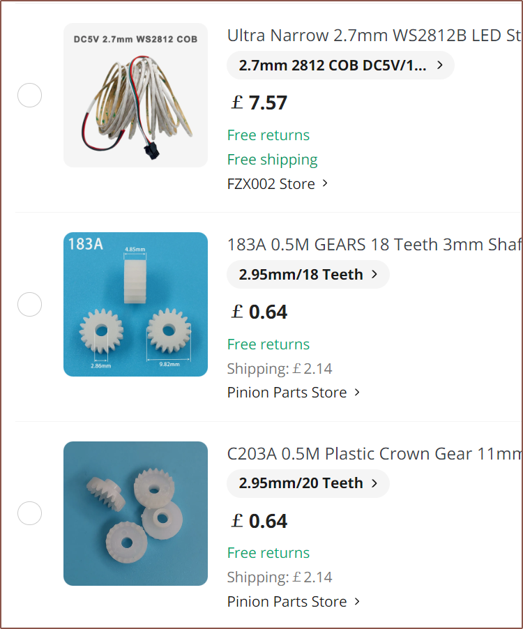
So after going through Pinion Parts Store on AliExpress, this is the compact solution I landed on after about an hour:
"Mkay... that should be a 15.6 : 1 reduction. Bit high but maybe it's ok?"
Then I started sketching the other gearing strategy planned to be used with a 58mm rotor. It was then that I realised that I just assumed "smaller number over bigger number" for the gearing calculation, and that the gearing ratio wasn't 2.6 : 1, it was 0.78 : 1! This was me when I put the new calculation into the Excel spreadsheet and saw the wattage numbers of motors such as Toroid-58mm and the 1656:
So I already weakened after that realisation, but the "Instant Damage" potion that took me down to "half-a-heart" (speaking in Minecraft terms) was when I then looked at my gearing strategy again and realised it's all backwards! I had created a 1-to-16 torque destroyer!
It took me over 12 hours to recover from that emotional damage yesterday.
Knowing that all the 50mm+ motors I had found now weren't going to fit, I went looking around. Most of the motors I found in the sub-40mm range all used 2mm shafts, and I can use a C202A for that.
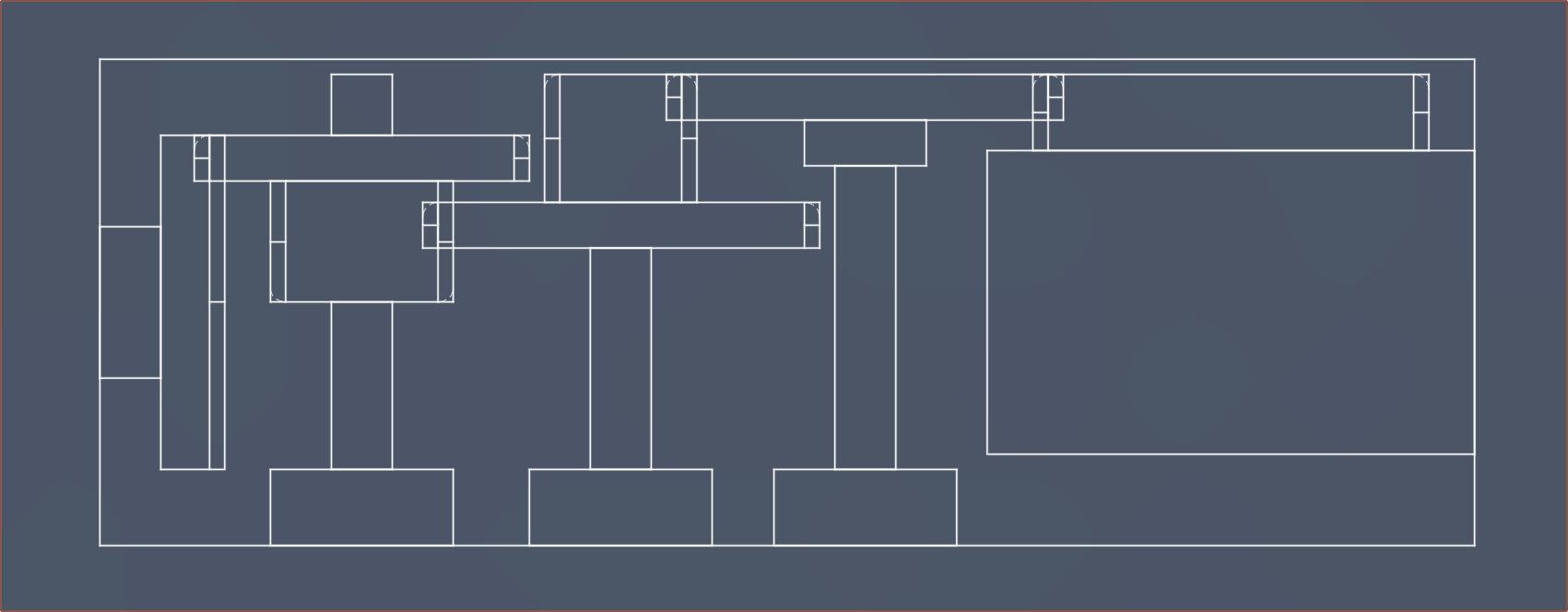
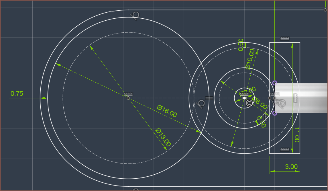
Today, I've converged on the following 16mm-wide solution, providing a reduction of 7.2 : 1:
It might also be possible to integrate the 242A into the print so that the teeth don't have to be printed. Also, not sure why Fusion wants to colour some lines blue when the sketch is fully defined.
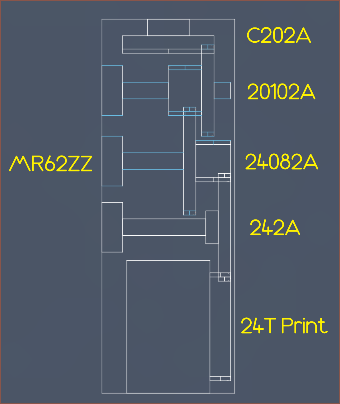
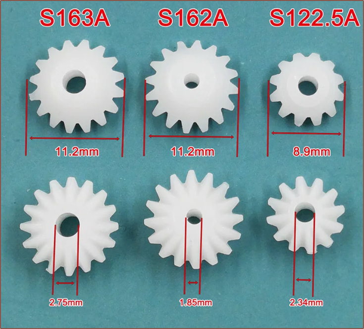
I've also learned how to read the names. 2A means "2mm shaft, tight". Then it's just listing one or both teeth counts. For example "24082A" means "24 teeth connected to 8 teeth. Tight fit on 2mm shaft.". "C" stands for "crown".
Additionally, the idea is to potentially use the same bearings inside Tetoroidiv, as well as omit the crown gear and connect the motor directly to 20102A for the thumb Tetrinsics.
The current centre-to-centre spacing between the proposed motor location and the pulley is 28.5mm, which should be enough to put the thumb Tetrinsic motor right beside the finger ones and still allow a square form factor.
The height of the gearing is defined by the largest gear, so that's why there are many with the same 24 teeth. The length of the gearing could be shortened slightly by using 18102A -> 22082A -> 222A -> 22 teeth print.
Looking at my options, i think the best thing to do now is make a prototype that doesn't include a motor.
This would also make it easier to implement if someone just wants to have an LED lit, force sensitive but otherwise basic slider, similar in nature to the encoders installed in some hobbyist keyboards.
At least if literally everything else about the current concept works, it would be easier to justify £50 and up for a prototype motor or spending days making my own.
[E2] The proposal... fails. I need a haptic source, where the lack of which was partially responsible for the non-use of #AirBerries and SpaceExplorer
[E2: May 1] - Renamed to a trendier "Tetoroidiv" to keep with the coincidental tradition of an ever so slightly longer name on each subproject;
Move the UV LED out of Tetrinsic's domain
I've computed a new Tetent solution, and started on an Itinervate one too, and it seems that the LED would be better mounted on the enclosure or PCB mounted with Tetrinsic, and not something to bundle along with it.
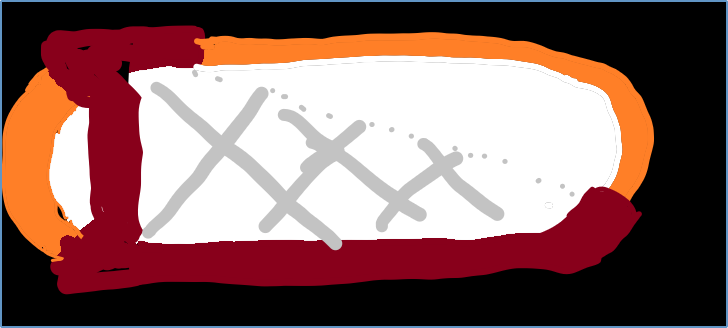
The above is the potential Tetent solution side profile. The top/right orange part is the belt, and the left orange is an LED that just lines up with the ones on Tetrinsic to give the illusion that it's continuous. In actuality, this curve has the 21700 cell.. The grey lines is supposed to be a 3D texture of diamond squares.
[E1] Cleaner, 1:1 sketch:
I'm calling this Concept Solution Epsilon, named after the Overlord character, because it's a potential solution and I wrongly thought ' Σ ' was capital epsilon until I looked it up right now.
Additionally, water resistance becomes mandatory.
I need to get "that 99.9% uptime". What I mean by this is that I want to be able to use it in 99.9% of reasonable situations. Thinking through thoughts during a shower or while running in the rain between locations is what I'd call a reasonable situation.
I think there's a notable and valuable gain from the difference between a 90%, 99% and 99.9% solution.
[E1] Unfortunately, the COB strip is IP20, so not off to a good start.
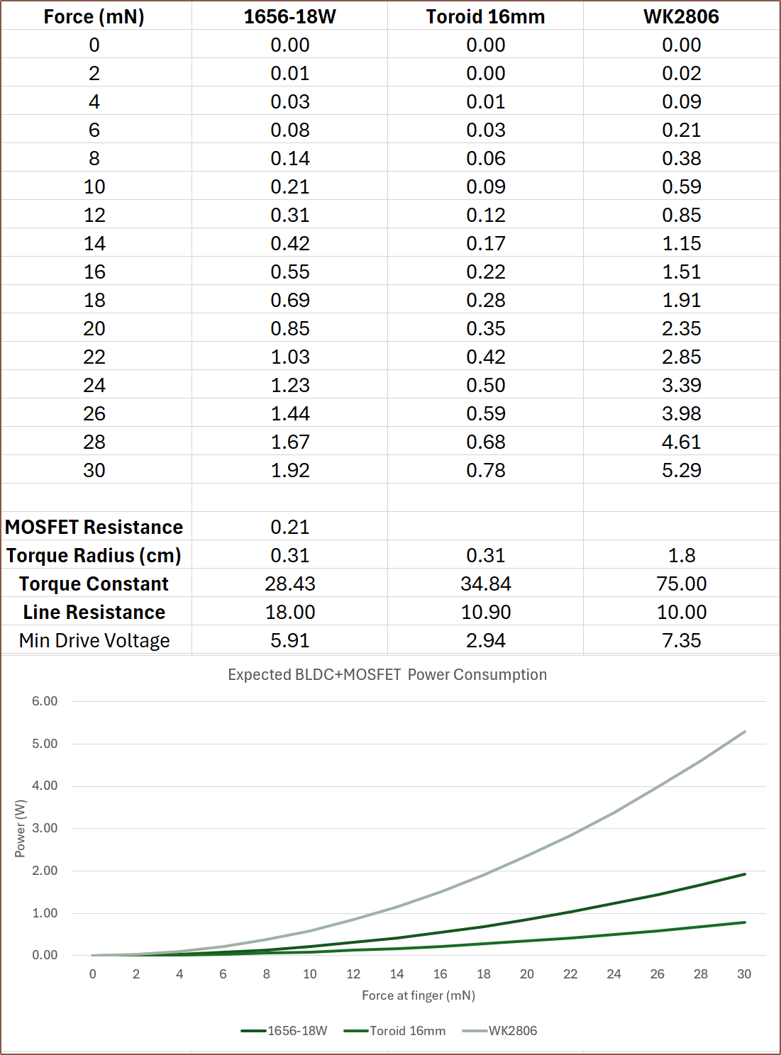
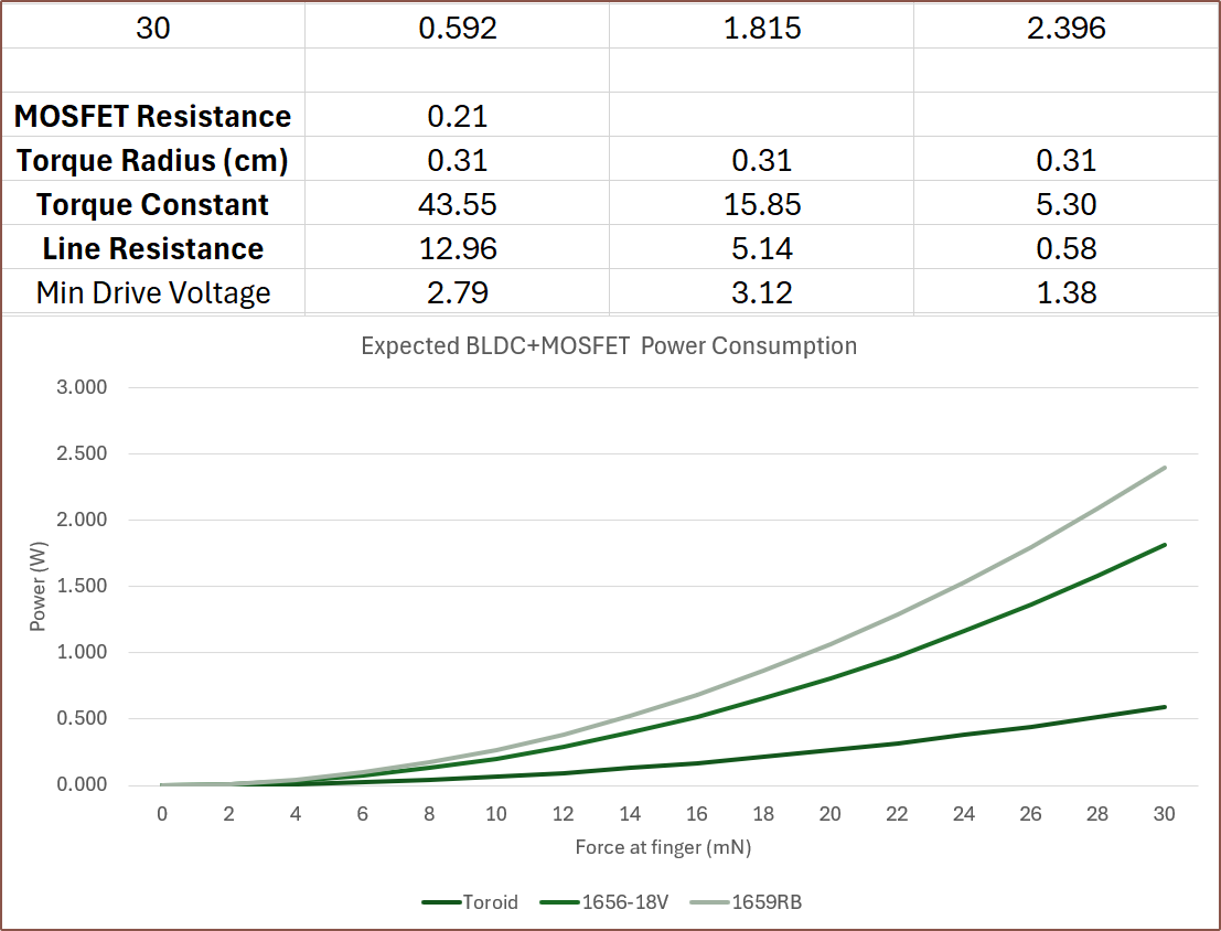
So I've added torque radius into the equation, which essentially is the effective radius of the force if there was no gearing or reductions. This paints a very different picture now that there is a 2.6 : 1 reduction for getting the power from the motor and into the belt.
Additionally, my current understanding that, all else being equal, the proportionality of rotor radius, rotor length and number-of-turns is quadratic, linear and linear respectively. Thus, I've calculated the expected torque constant difference from the motor mentioned in the paper with a 40mm long rotor and 78 turns. There is barely enough space for a 50mm rotor and that would increase the torque constant to 43.5. This calculation assumes that a 4-pole rotor can be obtained. I'd expect less torque if using the 2-pole magnet I found on aliexpress.
The $32 1656-18W motor also now has more favourable power consumption now.
I'll have to see what the torque numbers are when at the new max expected speed of approximately 1200RPM.
[Apr30] So I can see the amp-turns in action. I can fit 36 turns at 0.25mm diameter, 78 at 0.18 and 106 at 0.15mm, and with a 50mm rotor, they all get essentially 0.6W peak when putting in the resistances and compensating the amp. The only thing that changes is the minimum drive voltage, dropping down to 1.29V for the 36 turns configuration.
Thus, I think the strategy needs to optimised from other perspectives. For example, If I aim for a minimum drive just under 3V, such as the 78 turns configuration, I could use the battery voltage directly. I'm already planning to read the currents drawn by the motor, thus I'd save on voltage conversion losses. With this in mind, the 18V version of the 1656 makes more sense:
I've shuffled the order and added in the 1659RB motor mentioned in a 4th edit a few logs back.
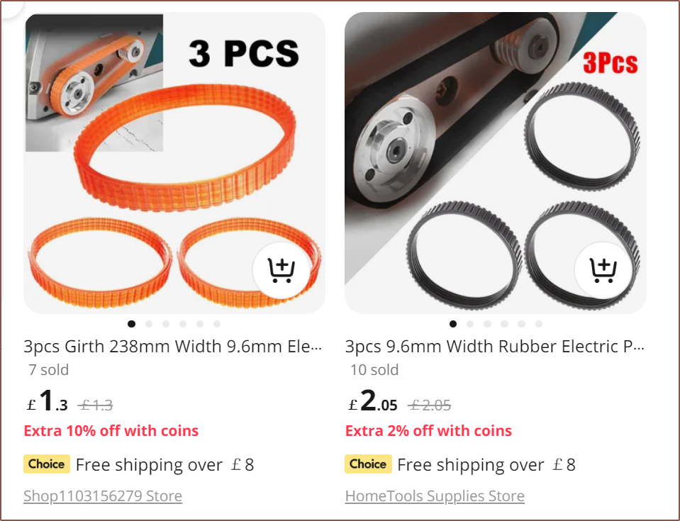
From the sketch I showed in the previous log, Fusion says that the belt length I need is 237.98mm... essentially 238mm. So I just searched "238mm belt" and coincidentally enough, such belts exist:
I've seen these belts before. I just didn't know that they specifically came in 238mm loops.
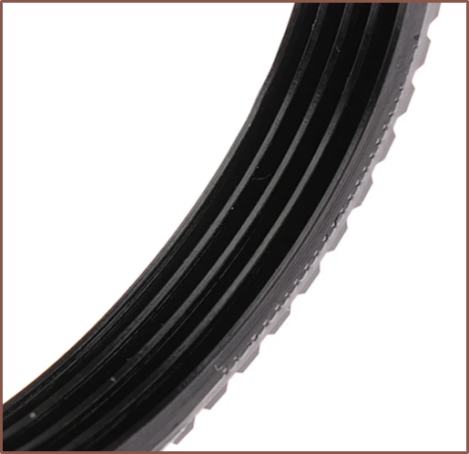
The black ones come with a thick looking groove on the underside, which is probably good for the sliding straights but not exactly ideal for the gear-teeth pulley.
The orange ones are slightly cheaper, and because they transmit more light, it's much harder to guage if the underside profile is the same as the black, but it's probably safe to assume so. What I do know is that the black one is rubber and the orange is polyuetherane.
The one standing almost looks like an optical illusion.
Unfortunately, both of these are 3.2-3.3mm thick, which is almost double the thickness that I'm looking for.
It looks flexible enough:
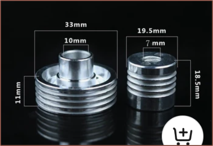
Looking at what this belt attaches to, the minimum turn radius might be OK if the smaller pulley is 19.5mm:
It also seems self-centering, meaning that I wouldn't need the flange and so I could probably tweak the gears to use something like this:20T crown -> 10T+20T -> 26T+pulley
12T+24T keeps ratios in nice integer values, though I can't find a tight-fit variant:
The final height is 24.5mm, which isn't ideal but doesn't fail any downstream solutions.
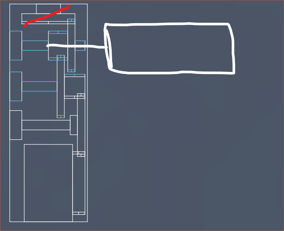
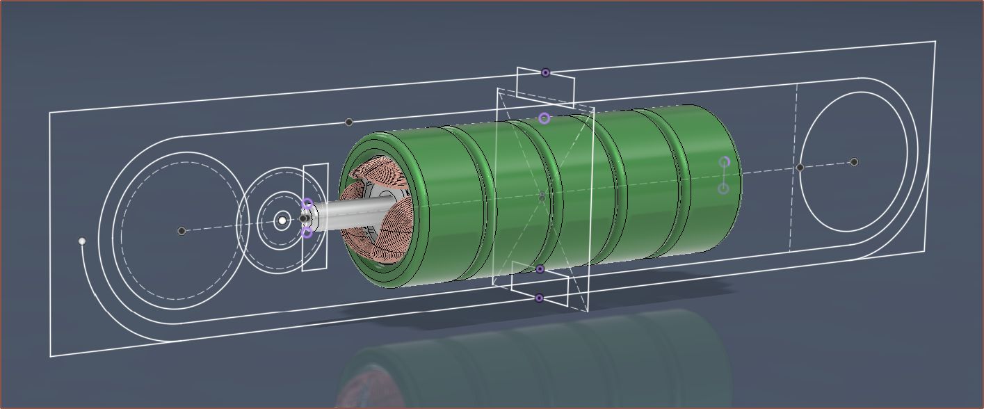
So this is the wireframe sketch of the proposed Tetrinsic strategy. The belt has just been approximated, but the actual belt path would go though both rectangles in the centre plane (which represent the cross section).
The plan is for the belt to roll on SLS printed, flanged 30T spur gears, and then connected to a crown gear (which I've never heard of until today) via an 18T gear. All gears are 0.5M.
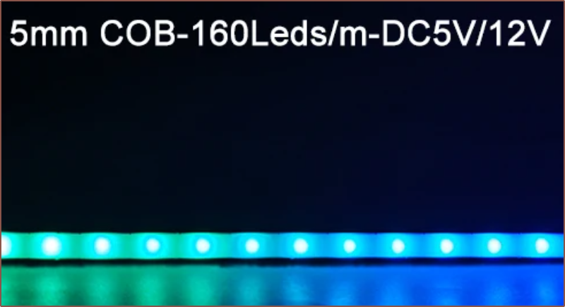
Additionally, addressable LEDs exist in a 2.7mm COB strip which has 160 pixels per meter. The plan is to have one strip on each side of the belt. I'd consider this a "side-lit" approach.
I've been able to find an Alibaba supplier of a 4-pole, 50mm long, N35 magnet which is $7/ea for 10pcs, along with $64 UPS shipping to the United Kingdom. Thus, the magnet is about £12.30/ea after VAT. For now, I'm going to try the 2x40mm N42 magnet approach.
I also believe that I should be using the line / terminal resistance for calculating the minimum drive voltage and 0RPM wattages, as at least 2 coils will always need to be powered in a 3-wire BLDC to complete the circuit. The power numbers look steep but also more believable.
VMOT = 5V seems like a good value as the LEDs also need this voltage.
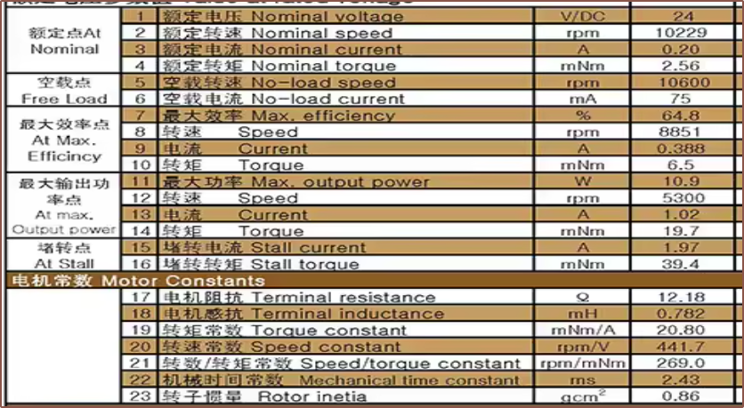
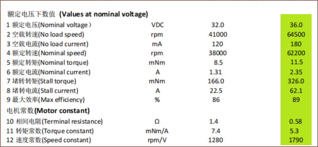
I asked to see the datasheet of the $32 motor and this is what I received:
The phase resistance is 1 / 2 of the terminal resistance (the resistance between two terminals, I presume), so it's 9 ohms.
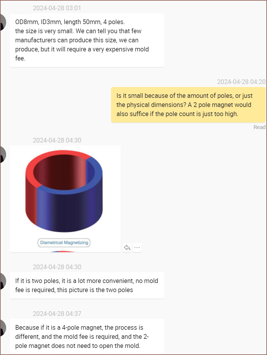
At this point in time, I'm also asking around for the rotor magnet and it's sounding like 1 pole pair is much easier to make than 2 pole pair:
It seems that Sinbad Motors has also gone with the 1 pole pair approach.
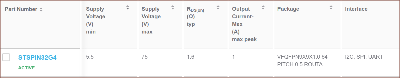
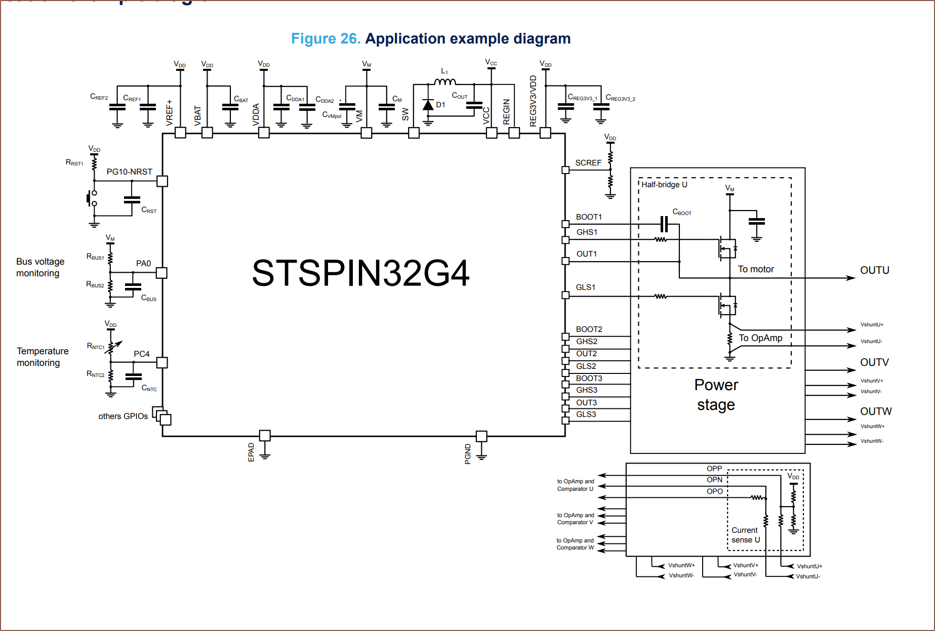
Additionally, the STSPIN32G4 is only a gate driver. Basically, I'd need to provide 6 MOSFETS to actually drive the motor, and that's a lot of traces:
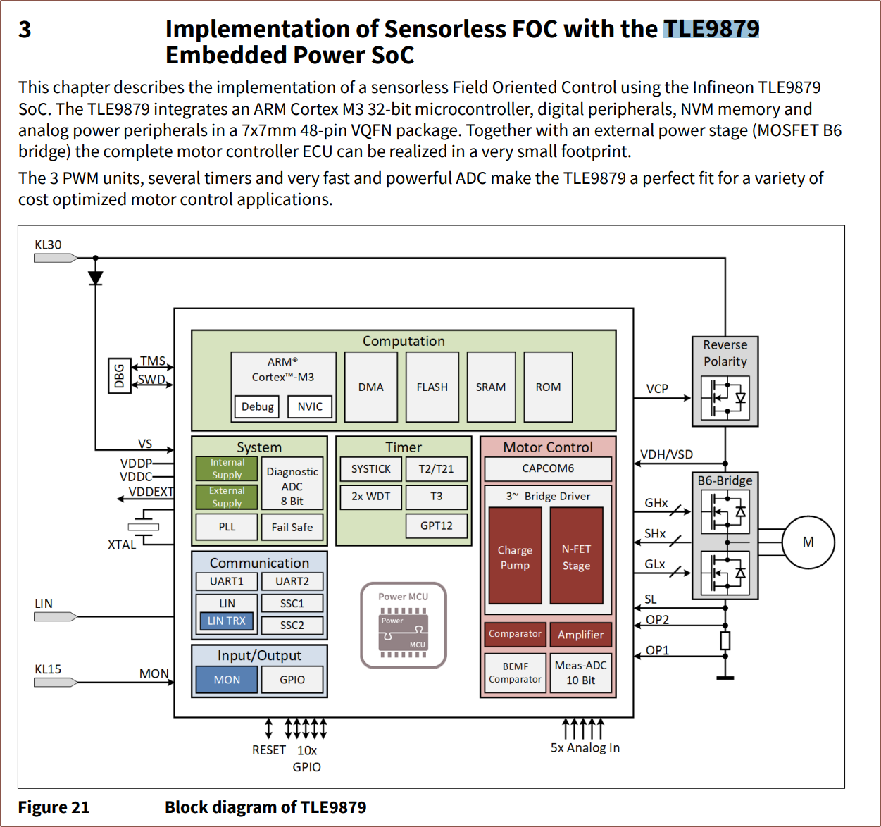
It seems that the TLE9879 is similar in this regard:
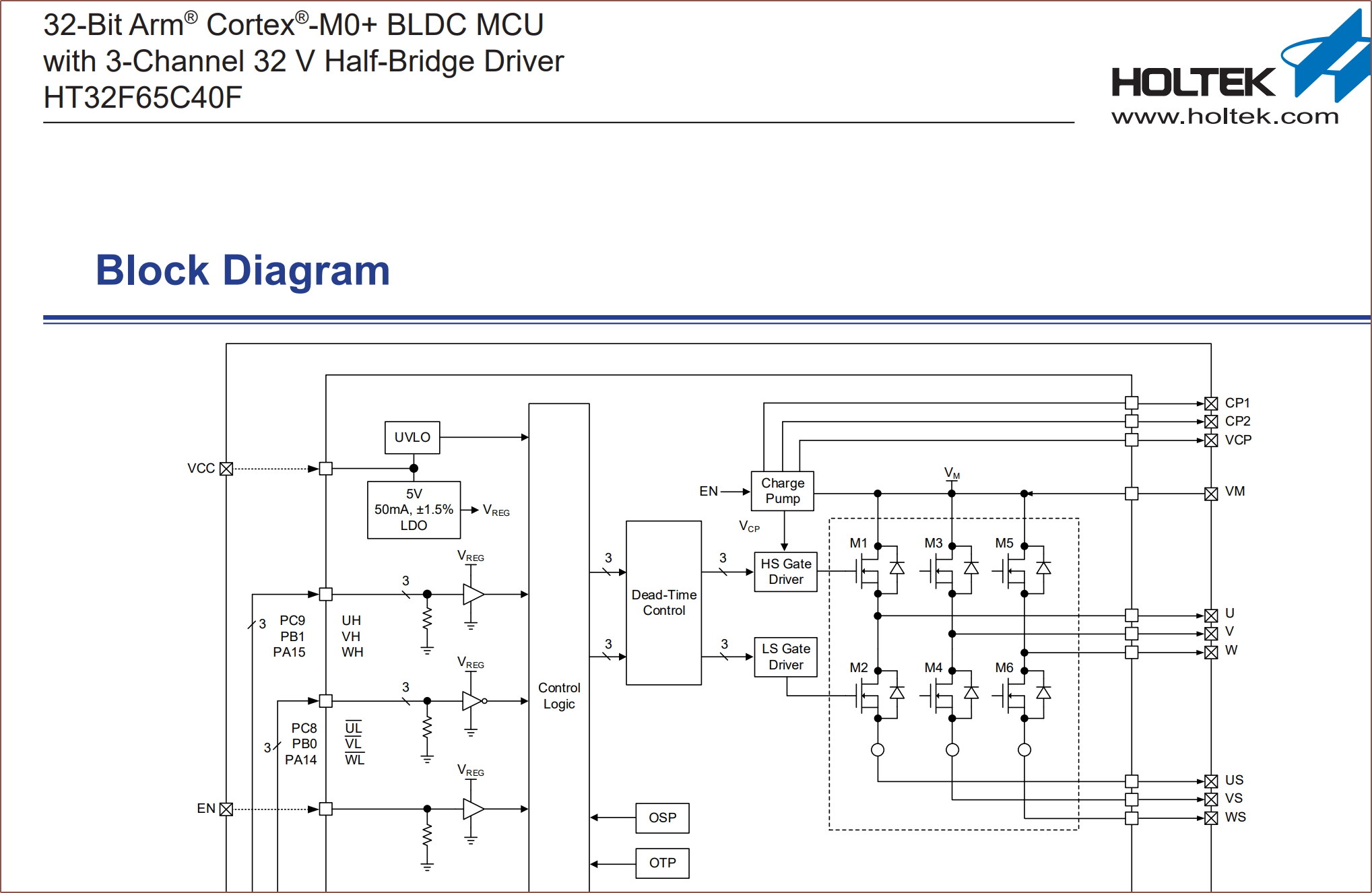
I thought that all that would be integrated, like this HT32F65C40F:
Thus, it does seem that I'll just stick with the original controller plan of using tSPI, which would only need 3 pins since it'll likely be the only SPI chip on the PCB.
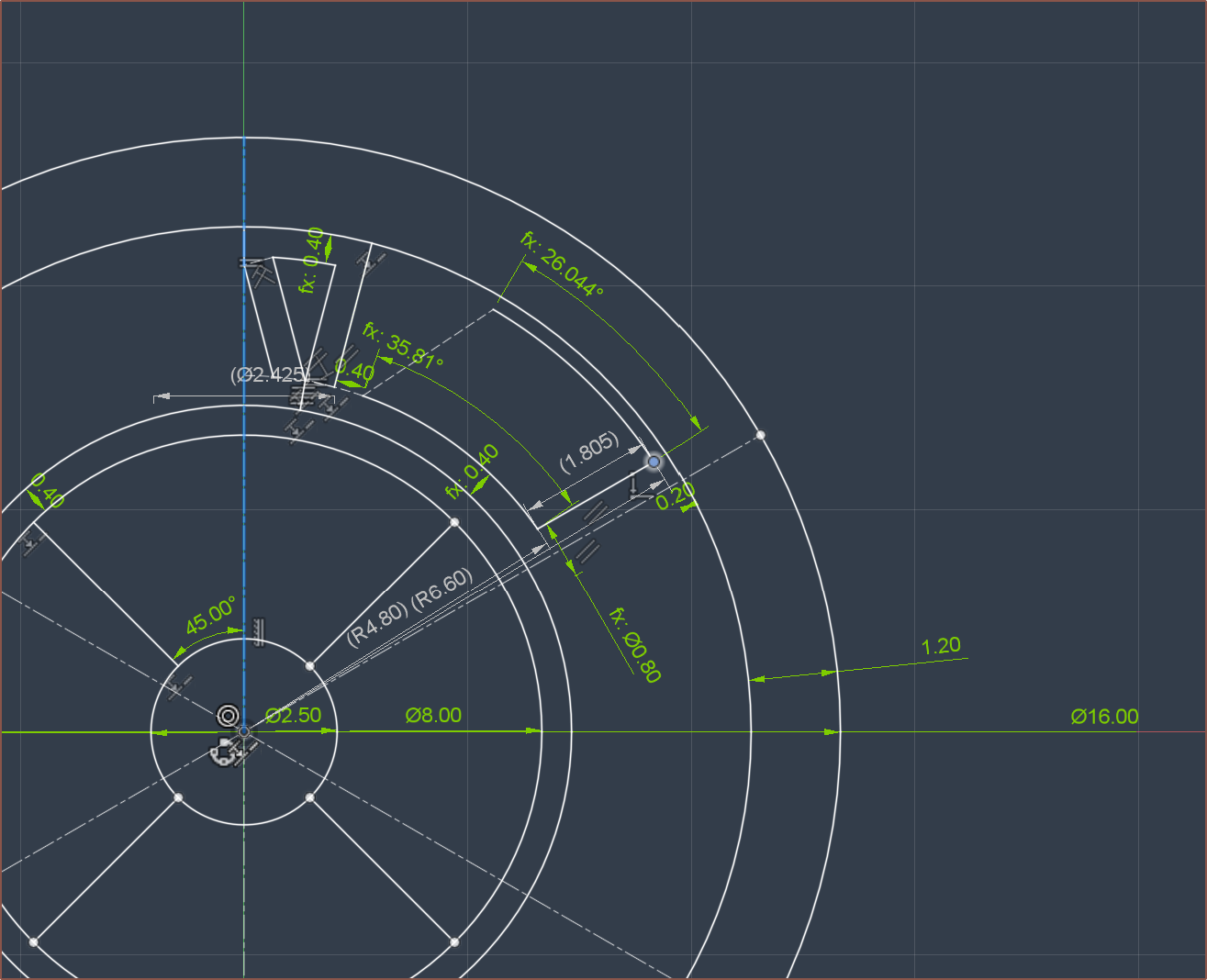
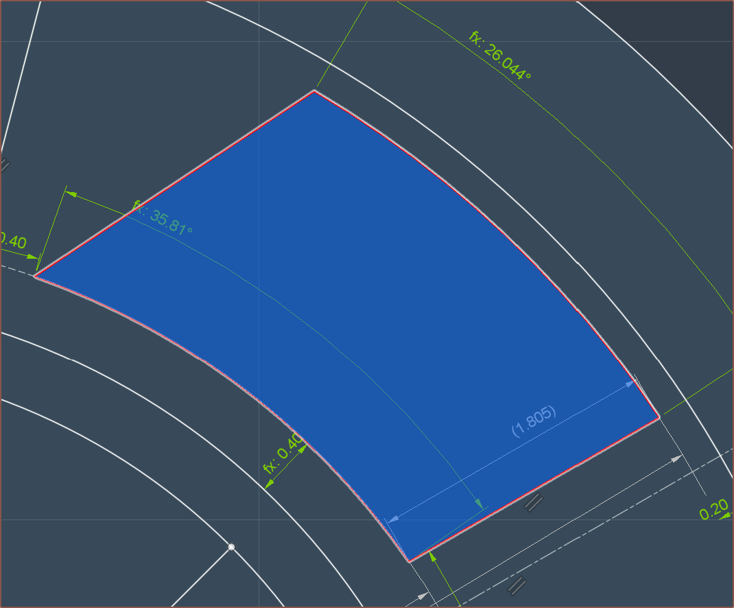
0.4mm spiral vase mode housing print (in PBT ideally, but ABS should be OK)
The space for the copper (1.805mm)
Coincidentally similar to the 1.85mm copper height in the 580KV motor.
Tolerance gap of 0.2mm
Outer lamination yoke that is 1.2mm.
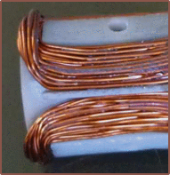
I opened up the 580KV motor I got to find out what size was used.
Copper foil?
You might be wondering what this is. This is the approximation of 3mm copper foil stacked on itself. Since copper smaller than the magnet width does not provide any torque (so I've heard), it makes more sense for the tape to hug the edges.
Assuming
a 0.06mm thick tape, of which 0.03mm is copper
90mm stator / rotor length
11mm on each end to connect the straights together
I got a copper tape length of 6060mm (6m) and a resistance of 12.1 ohms., which isn't great but kind of tracks compared to the 8.2ohm, $32 motor that looks like it's probably 55mm in total length and thus probably has a 45mm long stator. It obviously doesn't help that less than 50% of the CSA is conductive.
Copper wire
For the more traditional approach, it looks like there will be at least 15 * 8 = 120 turns (or 60 if I decide to double-up) using 0.2mm (32AWG) wire. Estimating for the extra space filling, it's probably going to be at or close to the 130 turns in the paper. It would also seem that a 3-pole-pair rotor would be ideal for this design.
Assuming that the average length to connect the straights is 9.4mm and that 138 turns are used, I get 27434.4mm (27.4m) per coil, which corresponds I get 14.7 ohms.
Is that high? Maybe? However, if this design -- with rotor of length 90mm and diameter 8mm -- can match the 75mN.m obtained with the paper's motor (rotor of length 25mm and diameter 11.5mm), The minimum driving voltage and power consumption would suffice:
If anything, I worry that the Kt would be too high and the minimum drive voltage would be lower than 6V. Additionally, manually winding dozens of coils for over 100 turns each sounds like it would be laborious. I could always double up the 0.2mm wire, but it seems that it would just be easier to work with 0.25mm wire:
Here, it seems that at least 80 turns would be present, probably something like 82. If my tolerances are good, I could probably fit a 7th row and perhaps get to 90 turns. For 82, the total wire length is 16301.6m and the resistance is 5.4 ohms.
Quick finger tests
So, just to make sure I'm on the correct page, I put my scale against the wall and pushed my fingernail for Finger2-4 (see below) and the max reading across the tests were about 300g, thus I'm correct in aiming for 30mN virtual-endstop force.
Secondly, I played some music, slowed down so that 1/8th of a beat corresponded to the time it took my finger to move 50mm. This is because 16 x PI = 50.3mm. Then, I used an online BPM tapper to get 1/4th, which was 220BPM. Thus, the top RPM I expect to see on the motor is >= 440.
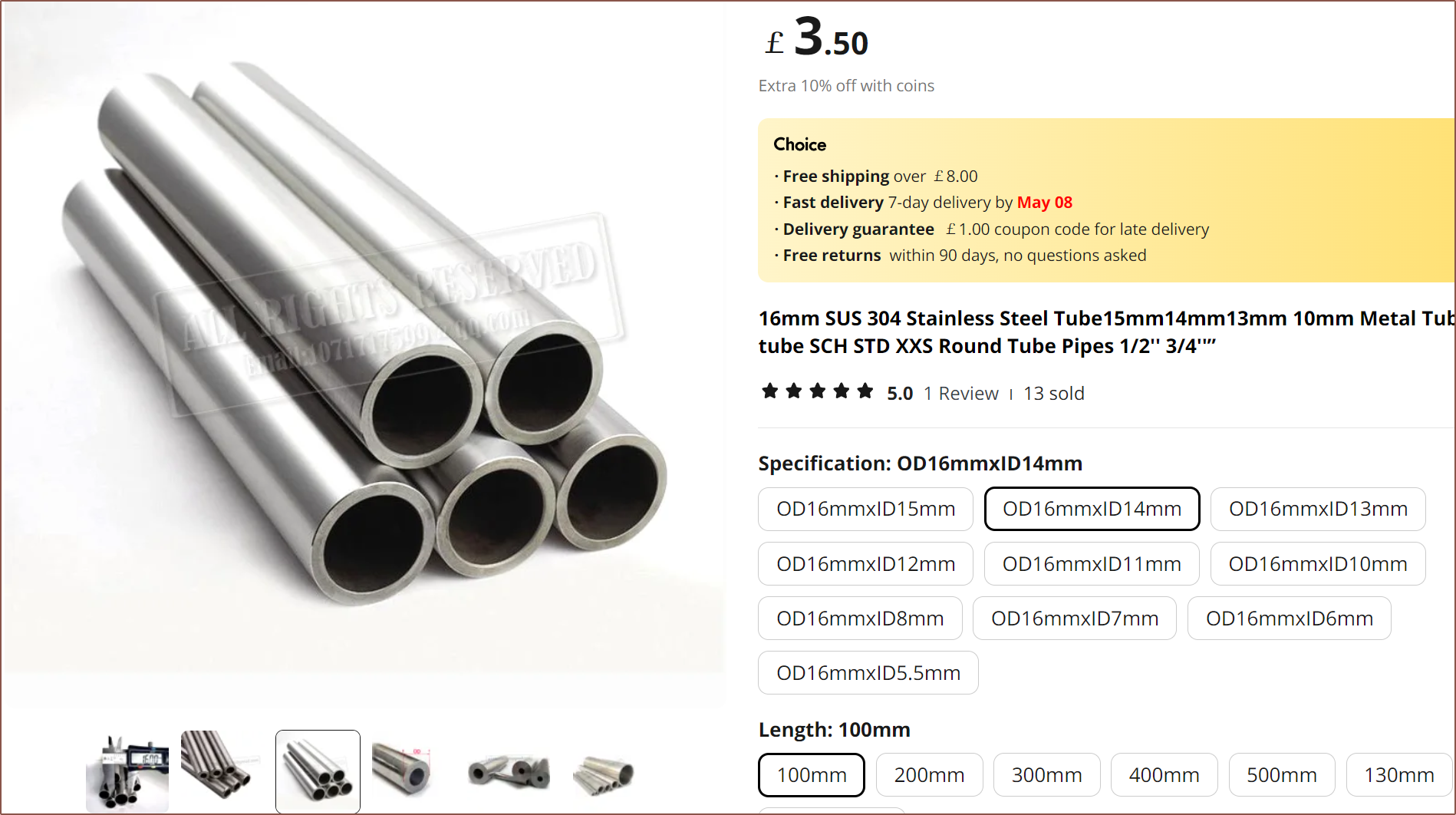
Tube instead of laminations?
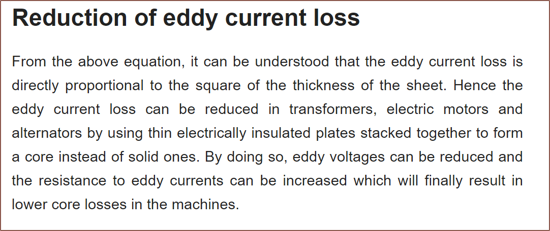
The reason I want to know the top RPM specifically is because eddy current losses are a result of how fast the magnetic flux is changing. Considering that, unlike 99.9% of motor applications, this motor is working at no / low speeds of essentially 500RPM max (unlike the 10K that the authors of the paper called "low speed"), I'm wondering if the eddy current losses will be low enough to use a tube of magnet-permeable material.
Stainless Steel 304 could be a good choice, as it's readily available and, unlike things like mild steel, doesn't corrode in contact with water. I don't know if magnetic PLA is more or less magnetically permeable, but stainless steel probably would do a better job of dissipating heat.
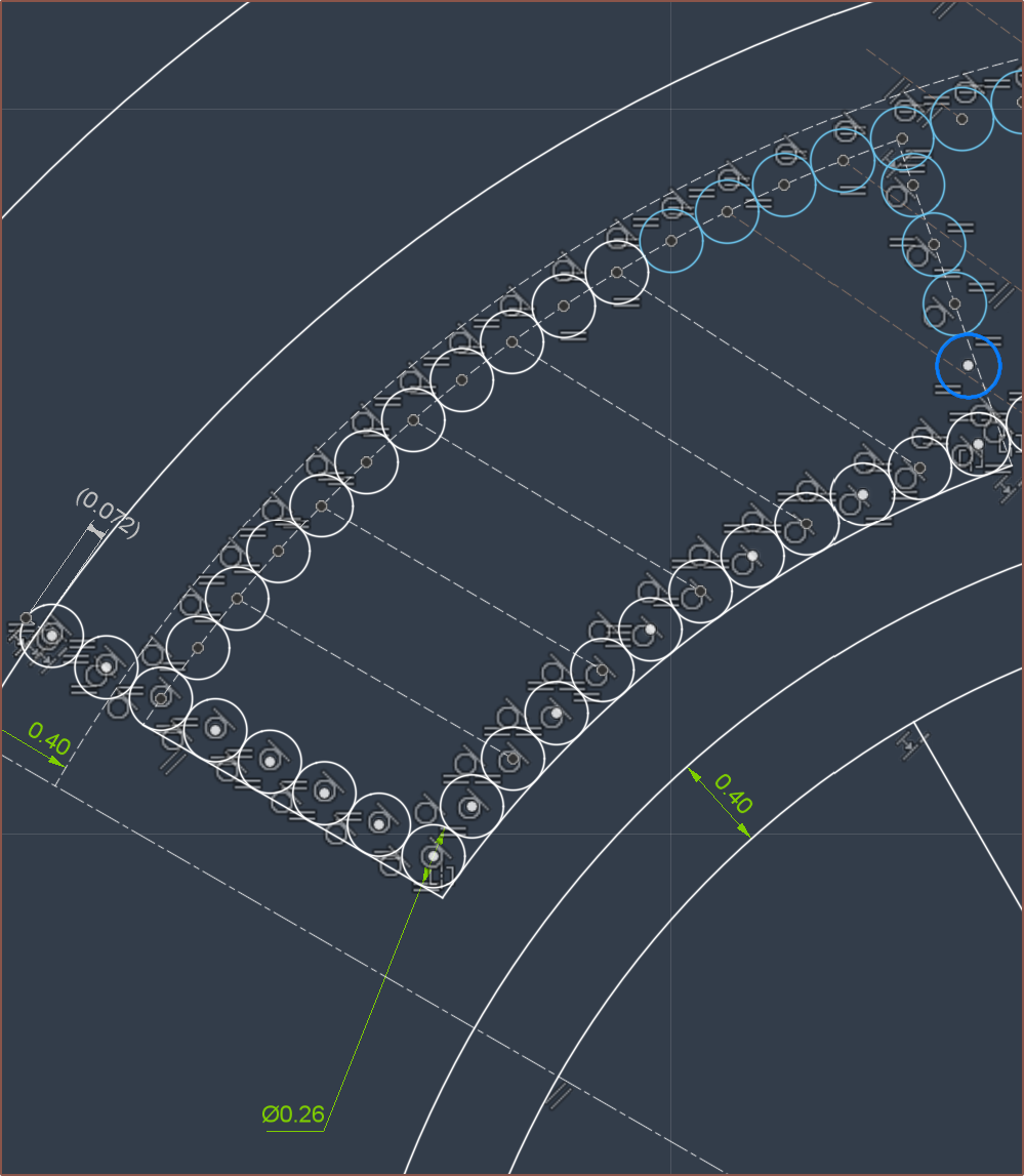
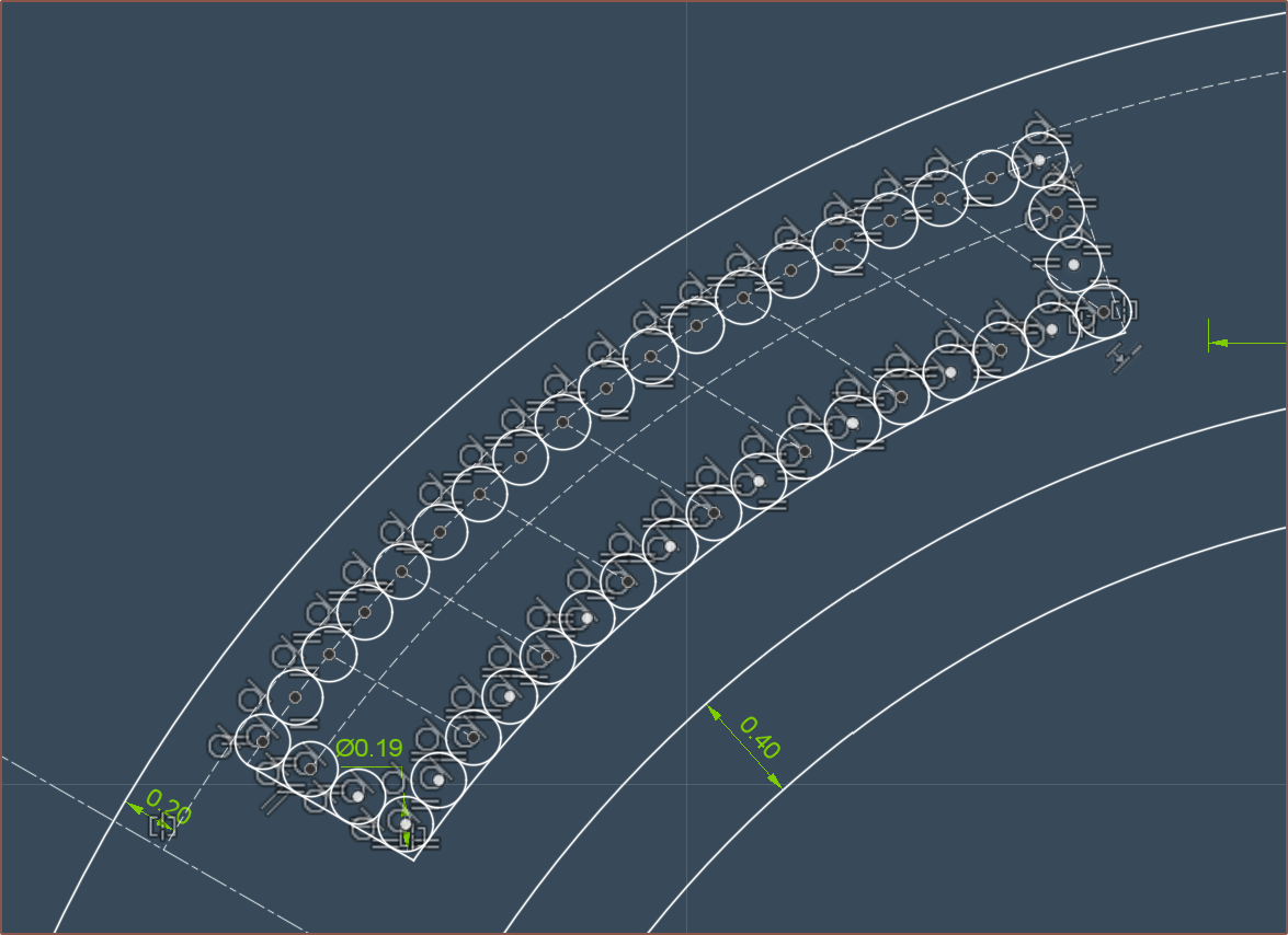
The paper says that the magnetic "air-gap" is essentially from the rotor magnet to the outer yoke and thus should be minimised, and that it's a balancing act between that and winding resistance. For this reason, and the assumption that stainless steel 304 is probably less permeable than the sheet steel used for traditional cores and thus needs more CSA to contain all the flux, OD16x1D13 seems like a good choice. It looks like I'd be able to get 75 - 78 turns:
Assuming that (due to the thicker wire, and the fact that there would probably be a curve and not a straight line like I assumed further above) that the average length between the straights is 13mm, I get 15450mm of wire for 75 turns, corresponding to 5.3 ohms.
Sketching in 3D
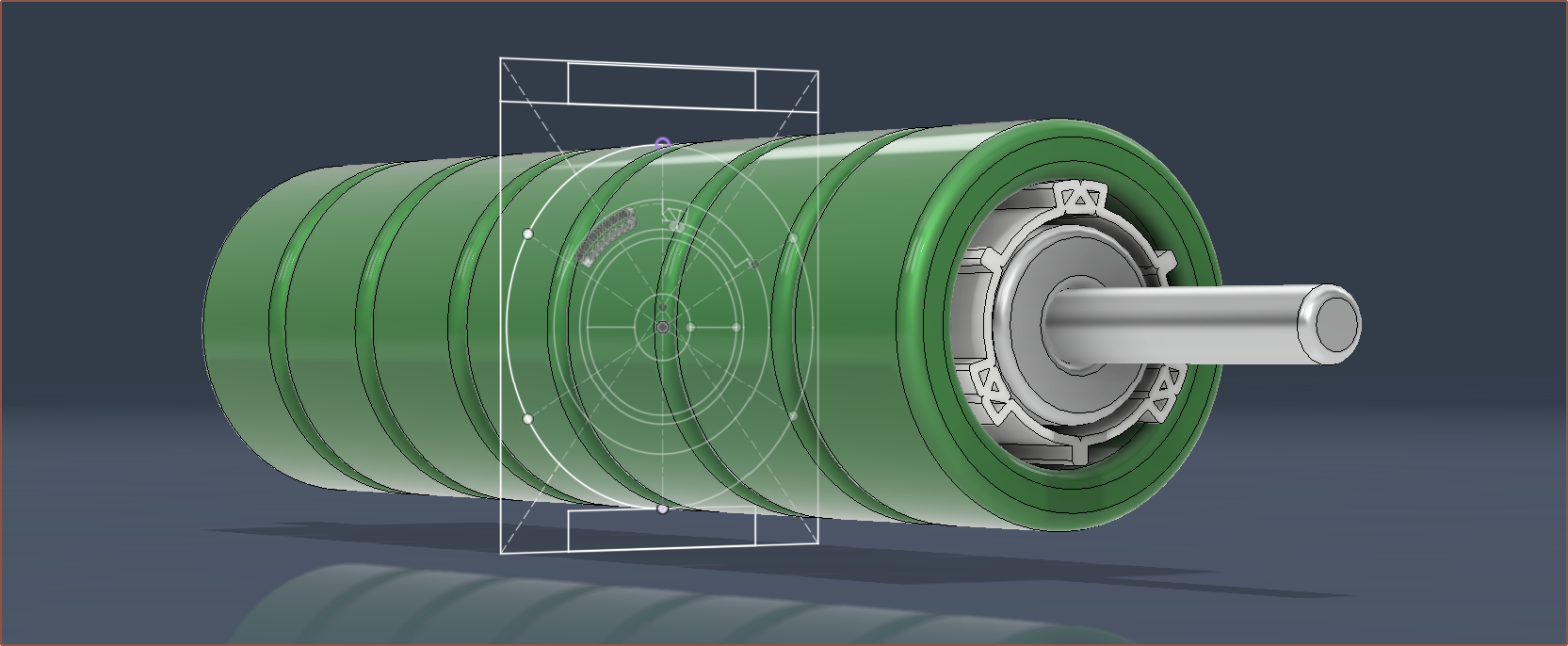
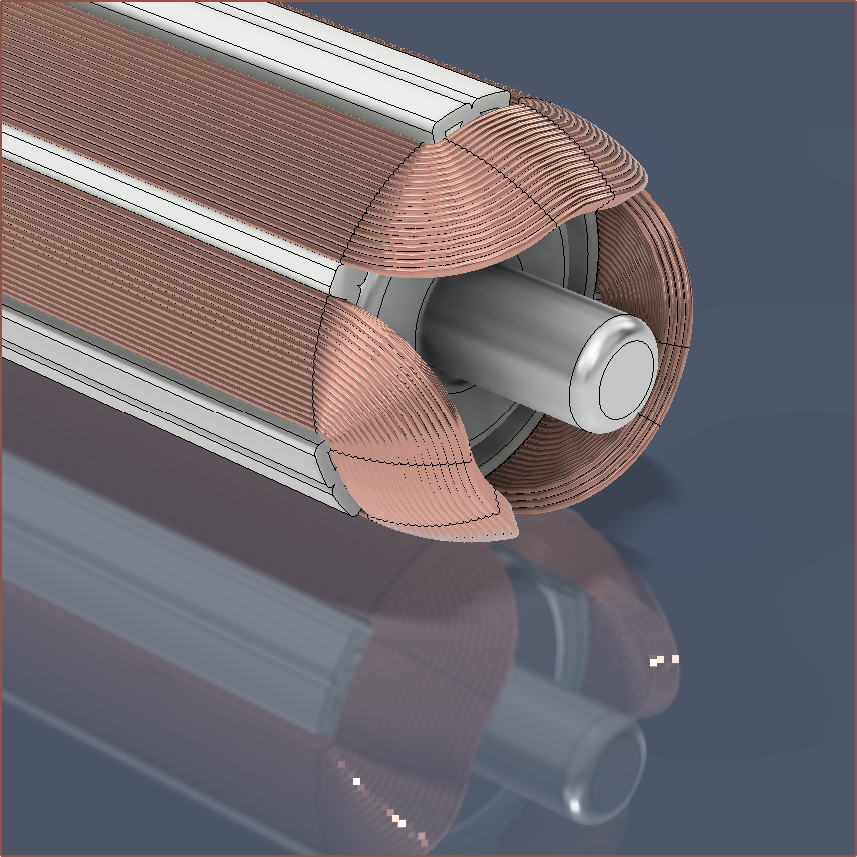
This is what I expect the "overmould" (as the paper calls it) would look like. It seems that I now just need to find a way to aquire a 3-pole-pair magnet ring for the stator. On the other hand, it sounds like the paper highlights that magnets with higher pole counts are more sensitive to the air gap. This kind of makes sense if I imagine that they're separate magnets instead of a single multipole magnet, whereby the field lines would extend a shorter distance if the separate magnets were smaller.100mm might actually be a tad on the long side, considering that the pulleys + belt would contribute about 40mm to the total length alone, along with another 10mm just for the bevel gear. #Teti [gd0022] can fit 140mm tops, and my not-so-temporary temp keyboard is 125mm. Doing some measurements on the #Tetrescent [gd0150] concept print, it does seem that I'd want to keep the length under 100mm and it probably is closer to the 60mm that I've been seeing in my motor search. The minimum stroke length of Tetrinsic needed is 52mm, so 60 should be ok.
Thus, the rotor length drops to 50mm, thus 9450mm wire length and 3.2ohms. Additionally, this custom motor could potentially be directly compared with the $32 motor, similar to how the authors of the slotless paper compared their motor against a reference. It thus may make sense to use a 3mm shaft over a 2.5mm one (chosen for the smaller bevel gear variant) so that they're otherwise interchangeable.
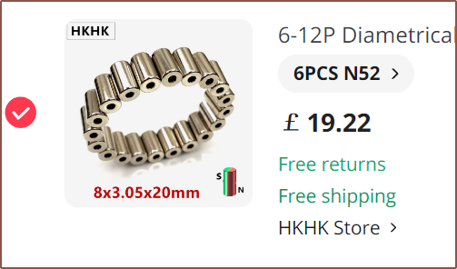
I've create an RFQ on Alibaba for the rotor magnet, and on AliExpress, I've coincidentally found multiple sellers of 8*3.05*20mm diametric (2 pole) magnets:
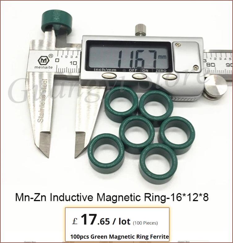
The slotless paper had a breakdown of normalised prices, and the magnet for the rotor was 52% of the entire cost, so I was expecting that it was going to be rather costly. I also found 16*12*9mm ferrite rings that are a tad bulky on the wall thickness:I'd only be able to get about 38 turns in with 0.25mm wire. This would likely be better wound with 0.2mm.[Apr28]
I looked into eddy currents, and it doesn't look good for the solid steel strategy:
Additionally, I'd have to cut the tube down to size. On the other hand, because of the overmould, it would be possible to instead stack multiple ferric rings/toroids to get the length desired. This stuff is used for things like transformers and inductors, and thus probably has the magnetic permeability and saturation thickness required for the job.
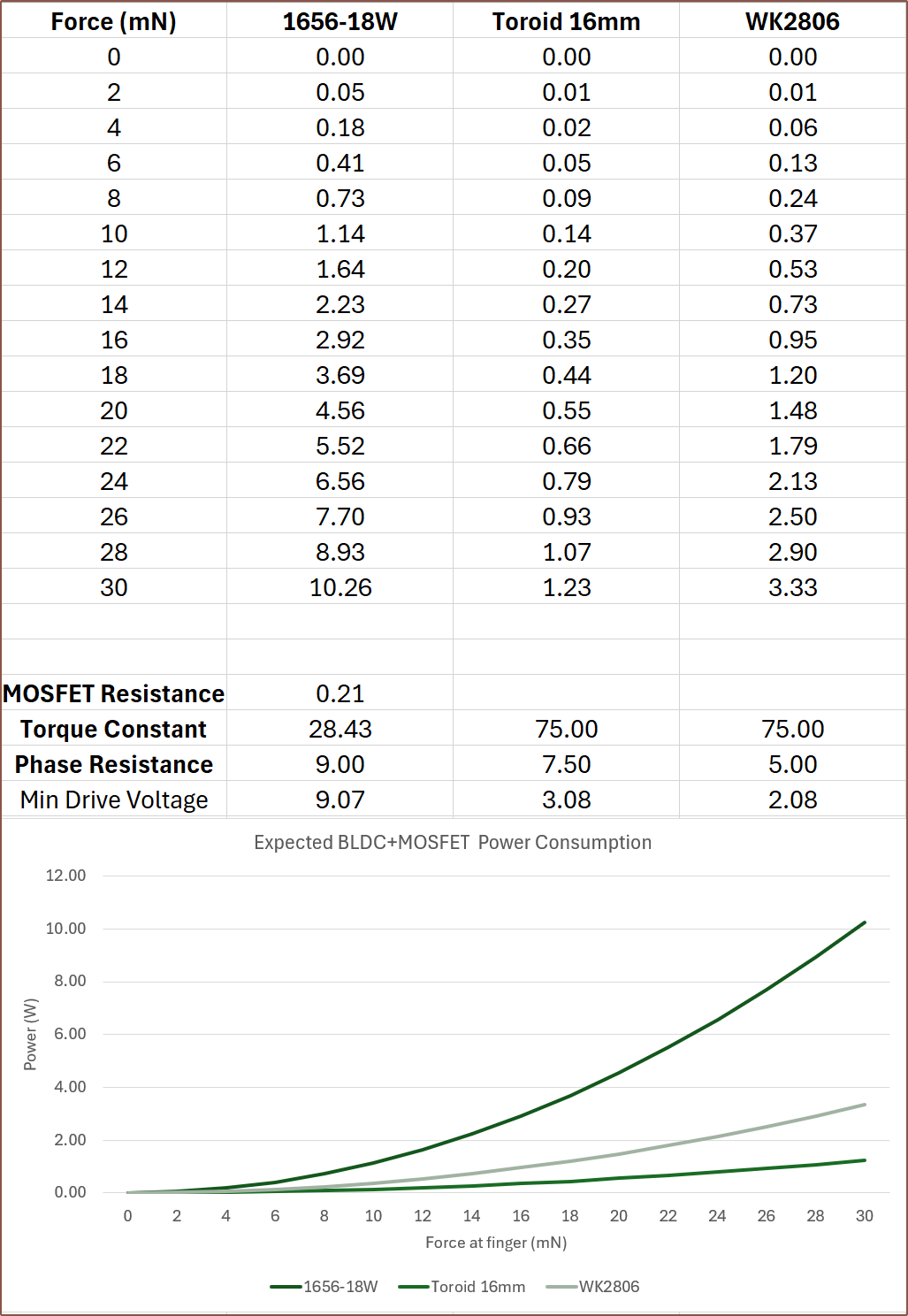
With 0.18mm wire, it's possible to have a phase resistance of 7.5 ohms from 78 turns and an assumed average straight-to-straight wire length of 13mm:
This is good, because the minimum drive voltage is 3.08V, meaning that I hypothetically should be able to use a 3.3V source for everything.
I think the Tetrinsic Toroid is a fitting name for this motor:
8.3mm toroid length x 7pcs, 80mm long 3mm shaft, 20mm x 3pcs rotor magnet
As you can see, I'm barely within the maximum target limits of 17mm x 21.8mm, considering that the FSR is 0.25mm and the UHMW tape is probably similar. I'd need a 1.8mm thick belt to stay within limits. As mentioned previously, these limits are so that a finger spacing of 18mm and a body height of 25.4mm can be obtained.
I'd also like to see if I can fit the hall sensors directly inside the motor, since the rotor is a 1pp diametric magnet and all, and so it makes little sense to then stick another one just so that I can get a Sin/Cos readout.
N52 is only about £3 more (so £1.50 more per motor), so I believe it makes sense to go with that. On the other hand, the video below states that magnet strengths come in a range and N52 is the hardest to get consistent, so it might be better to go with N42 since this rotor would be comprised of 3 magnets.
BOM
Thus the incl-VAT cost is already in the ballpark of £15.50 for the magnet, yoke and coils, and a solution will likely converge at under £15/each for the shaft, bearings, printed parts and hall effect sensors. I might also need glue to keep the ferrite toroids together and/or seal from liquids.
Depending on length considerations and the space needed to terminate each end of the motor, I might have to go down to a 40mm stator, which has the benefit of reducing the BOM by £3.84.
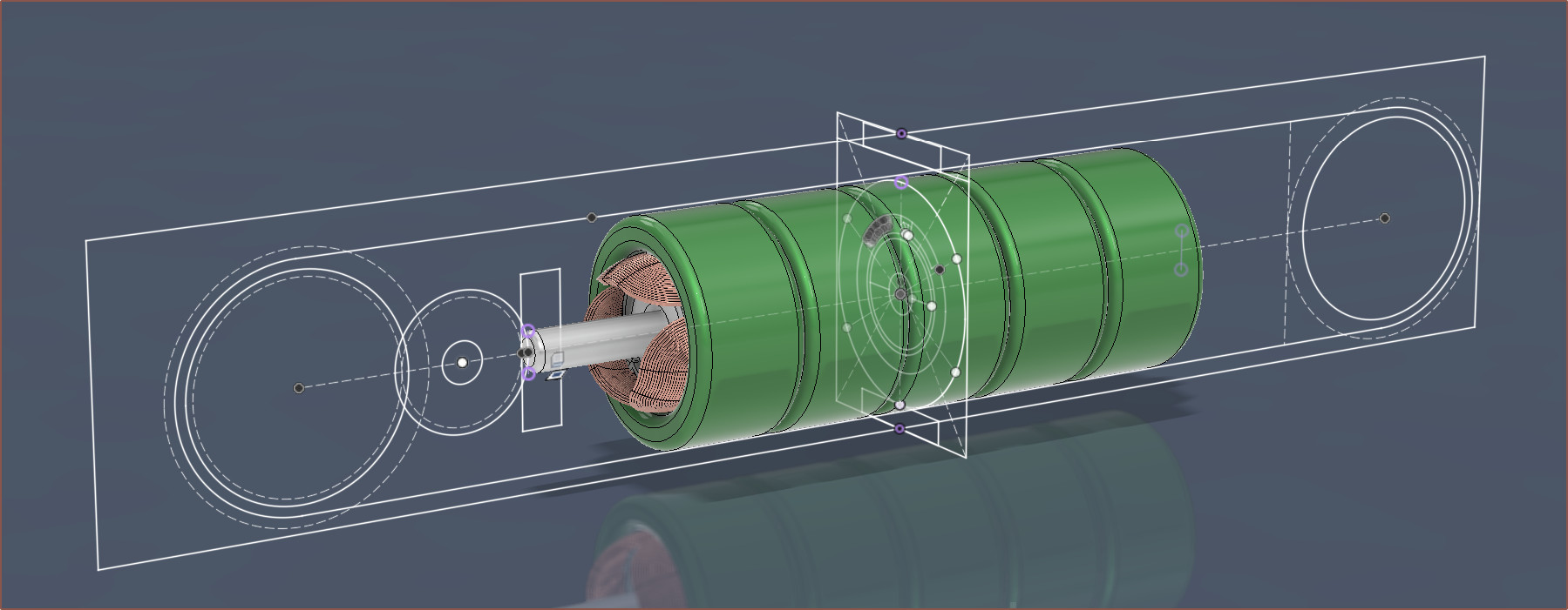
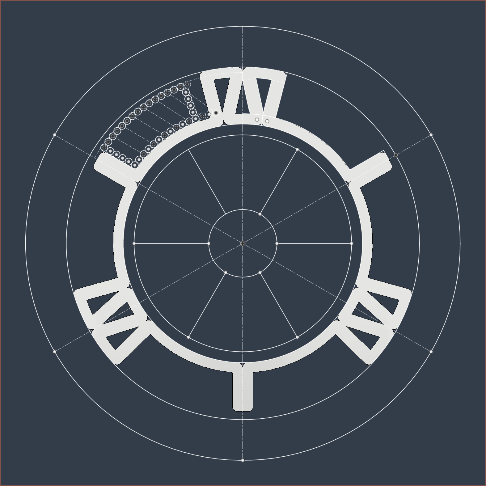
More modelling
Surprisingly, it didn't take much effort to model in the pseudo-coils:
Thanks, Fuson. I thought it was going to be an entire ordeal with multiple crashes or something with so many faces, but no it's just business as usual.
So I went over to the SmartKnob View discord to try and find some answers on motor options. The user K(at)B (the one behind the Ratchet H1) noted the potential implications of airlines likely not wanting to take belts that emit magnetic fields. I also had the concern that these magnetic fields are likely to interfere, especially if a Tentrinsic for the thumb is used.
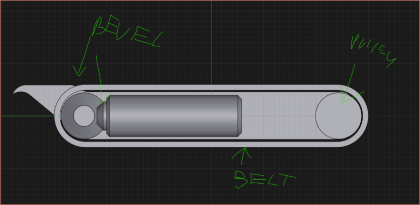
He then suggested this:
In practice, I'd expect to need 4 gears, not the two shown in the 3D sketch; 2 plastic 0.5M bevel gears and then 2 more gears that transfer the load to the pulley for the belt. He also suggested FSRs, and there happen to be long ones for an ok price, especially since an MCU ADC would be able to read it instead of requiring a fast but expensive 24-bit ADC.
This video shows that scissors can be used to cut the FSR to the required length if needed:
[Apr 27: Edit 3]
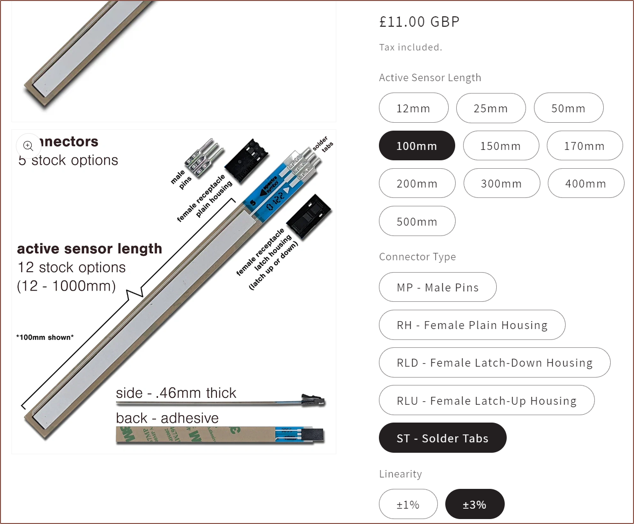
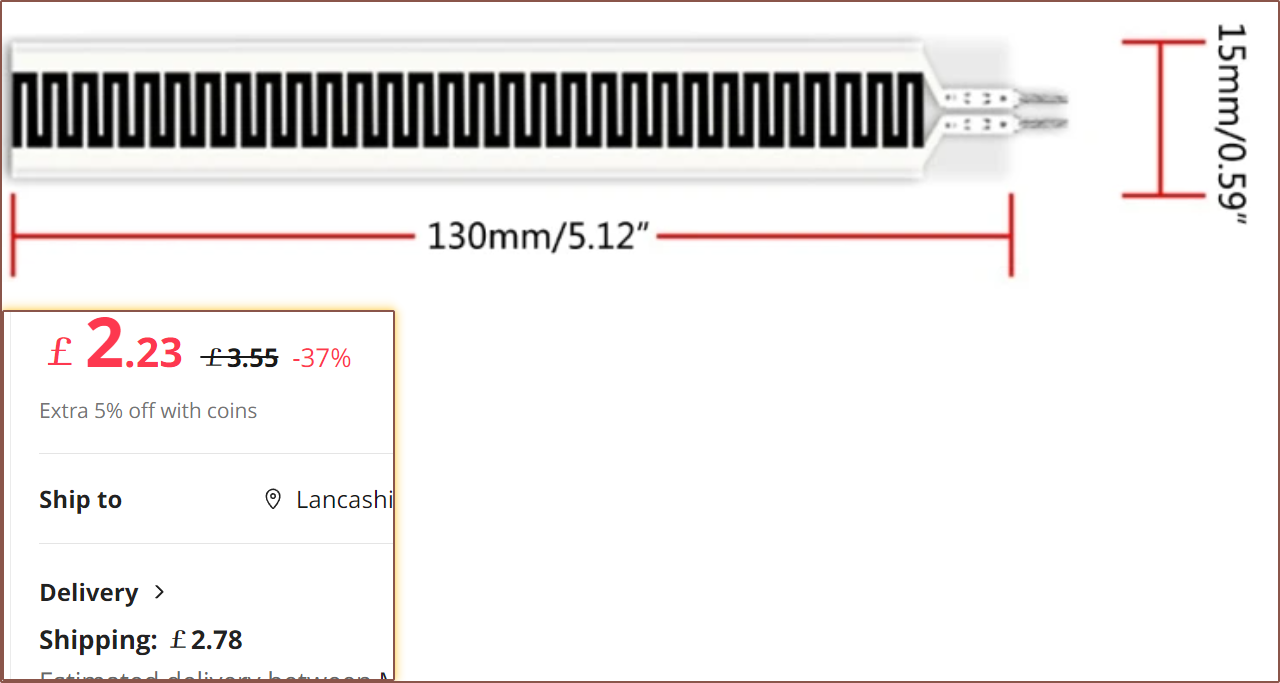
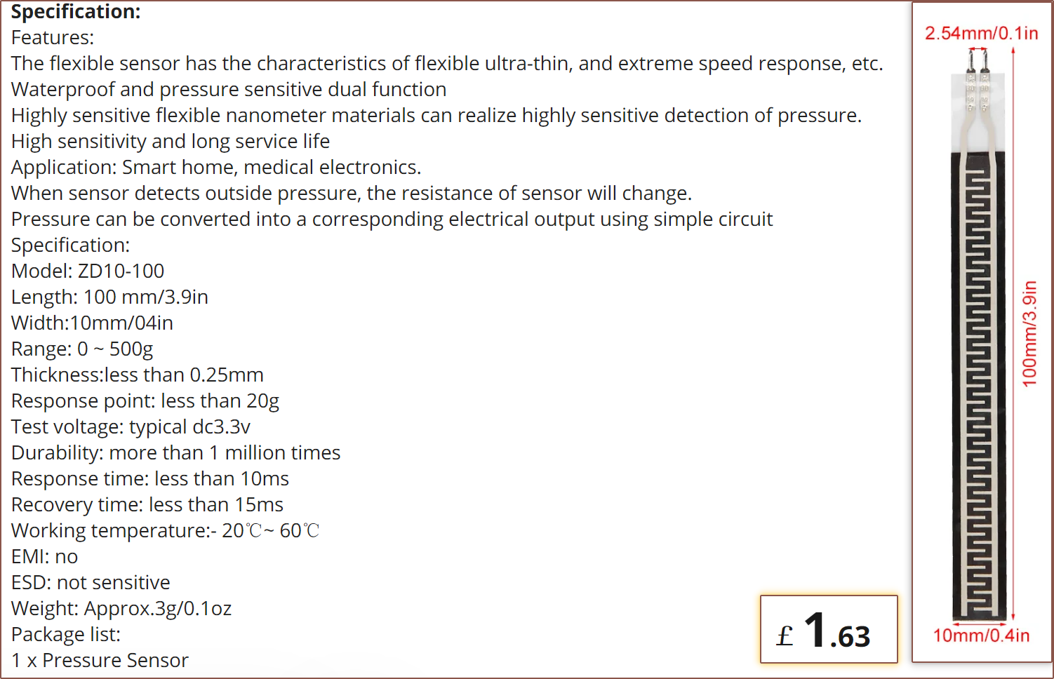
It seems that there's an even more ideal sensor, that works in the 20 - 500g range and is 10mm wide, which are both attributes that I'm looking for. There's also a schematic which essentially says that I can put this in a voltage divider along with a 10kOhm resistor and feed the output voltage to an MCU.
[End of Edit 3]
Thus, this was the start of searching for my motor options. Since 18mm Tetrinsic spacing seems more like "the standard value", and many motors seemed to be 16mm diameter, it makes sense to set the new maximum width of a solution to about 16-17mm.
Things I learned about motors
I think it's best if I fist provide some reference material that better helped me understand what to be thinking about when looking for a motor:
Lower KV motors are designed to be run at lower speeds and more likely to have minimal cogging.
KV seems almost irrelevant for coreless / slotless motors that have 0 cogging.
Torque for this application needs to provide 100 - 150gf continuously and over 300gf peak.
This is because the former is needed when emulating an analog stick. This site suggests that 75g is "standard", 100g is "hard" and 150g is "strong". Due to potential frictional losses, it's probably better to slightly overspec the standard torque, and that's why I'm aiming for 100gf minimum.
The latter is to emulate physical limit stops, and isn't expected that the motor will need to produce this torque for more than about 500ms.
Torque is proportional to current. That's it. Just current.
It was a bit surprising when I found this out, hence the emphasis.
The voltage determines the maximum RPM of the motor. This is due to back-EMF generated when the motor is spinning. If it's not spinning, there's no back EMF.
The voltage and phase resistance determines the max current that can be sent to the motor. It seems that the aim is to get a low PR as that means lower voltage, which results in exponentially less power used.
It seems that the torque constant (Kt), mN.m/A, is more important than the voltage constant (Kv).
Smaller wire = more coils = lower Kv, but less current can go though said wire so the effect is cancelled out and thus Kv has no real connection to Kt.
Frameless
I noticed that, from looking at motors found for the Smartknob View, there were a few motors that were shorter than 15mm. The 2204 260KV motor, for example, is 13mm. However, looking at images inside the motor, it seemed that there was a notable amount of unused space inside. Some time later, I came across frameless motors, where just the stator and rotor magnets are sold:
Long story short, these are the only options available, but the good news is that I just need the 1 solution and the WK2806 seems to provide!
Phase resistance: 5 Ohms
Kv: 121
Nominal current: 0.81A
Nominal torque: 600nM.m
Stall current: 1.22A
Stall torque: 900mN.m
Now, you may be wondering "Those seem to exceed what you need. Why not go for the 2205?". Well the issue is that the ball chain has a minimum turning radius, and even if it didn't, the physical motor has it's own radius. This means that the chain is closer 2cm away instead of 1cm from the pivot. Hence, for 150gf, I need 300gf.cm.
The magnet rings for the 2205 and 2208 are 25mm and 34mm respectively and #Tetent [gd0090] will still pass whether its thickness is 31mm or 40mm.
I am in contact with a different seller of the same frameless motor on Alibaba and, currently, the deal seems to be $6/pc and $50 shipping, which after tax works out to be cheaper for 10pcs than through Aliexpress. I feel like the shipping is a bit steep and I should ask if there are slower but cheaper options. The seller did offer to offer to add 2 spare magnetic rings as it's brittle.
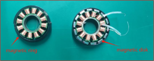
I asked about the cogging performance and I got a video of the fully-assembled motor (PM2806), which uses the "magnetic disk" version:
The ring is snapped in two in this image, showing its brittleness.
The disk has slightly more torque and the ring is smoother, so i've been told.
The torque metre recorded a max torque of 0.04kgf.cm, which corresponds to 40gf.cm and thus 20gf on the belt, which is on the lower end of scroll wheel encoders:
It's expected that the ring magnet would have even lower cogging.
Anyway, since the nominal torque is fine, I should be able to drive the motor at 4.0V:
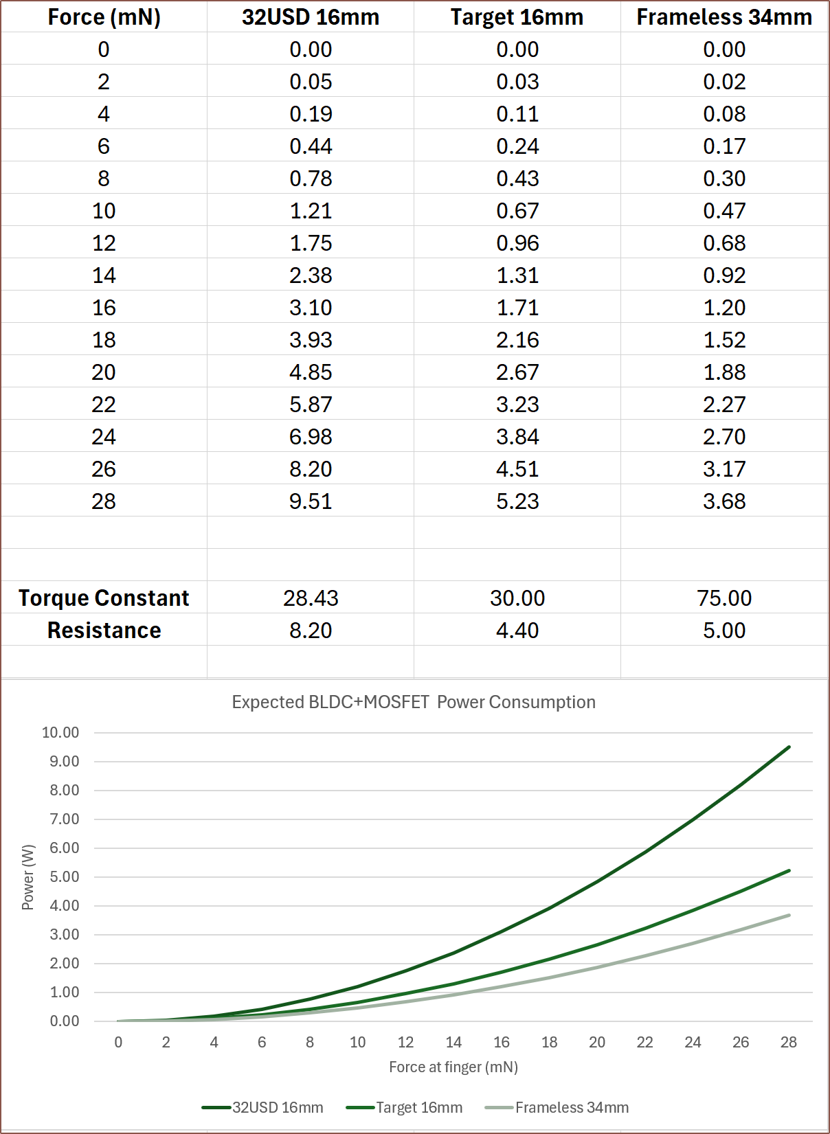
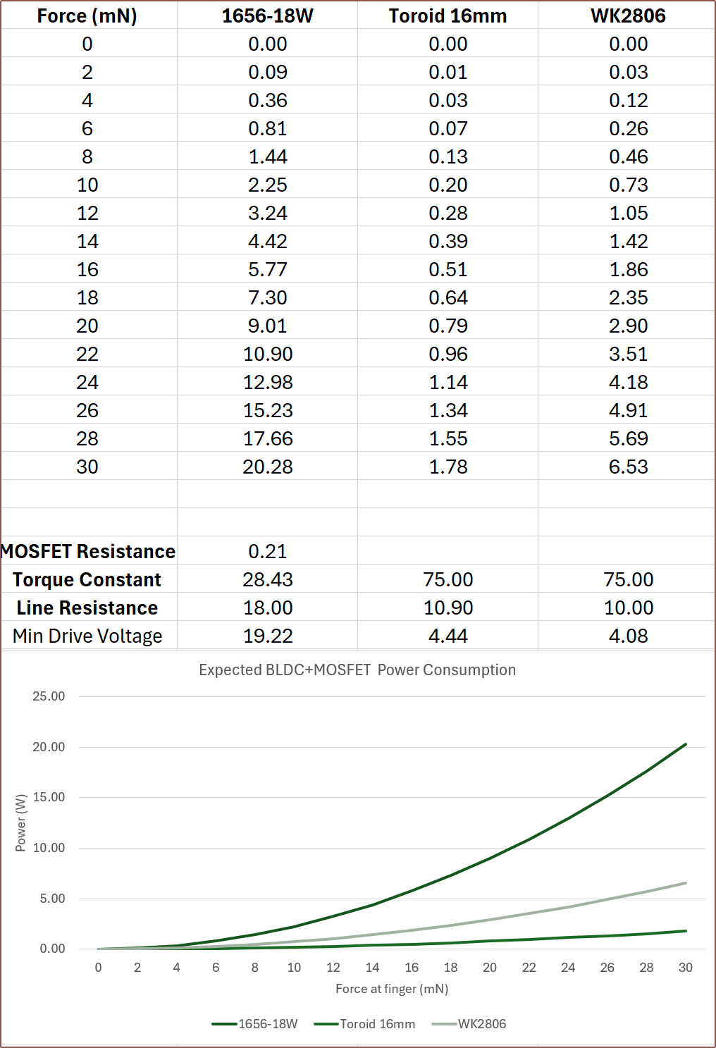
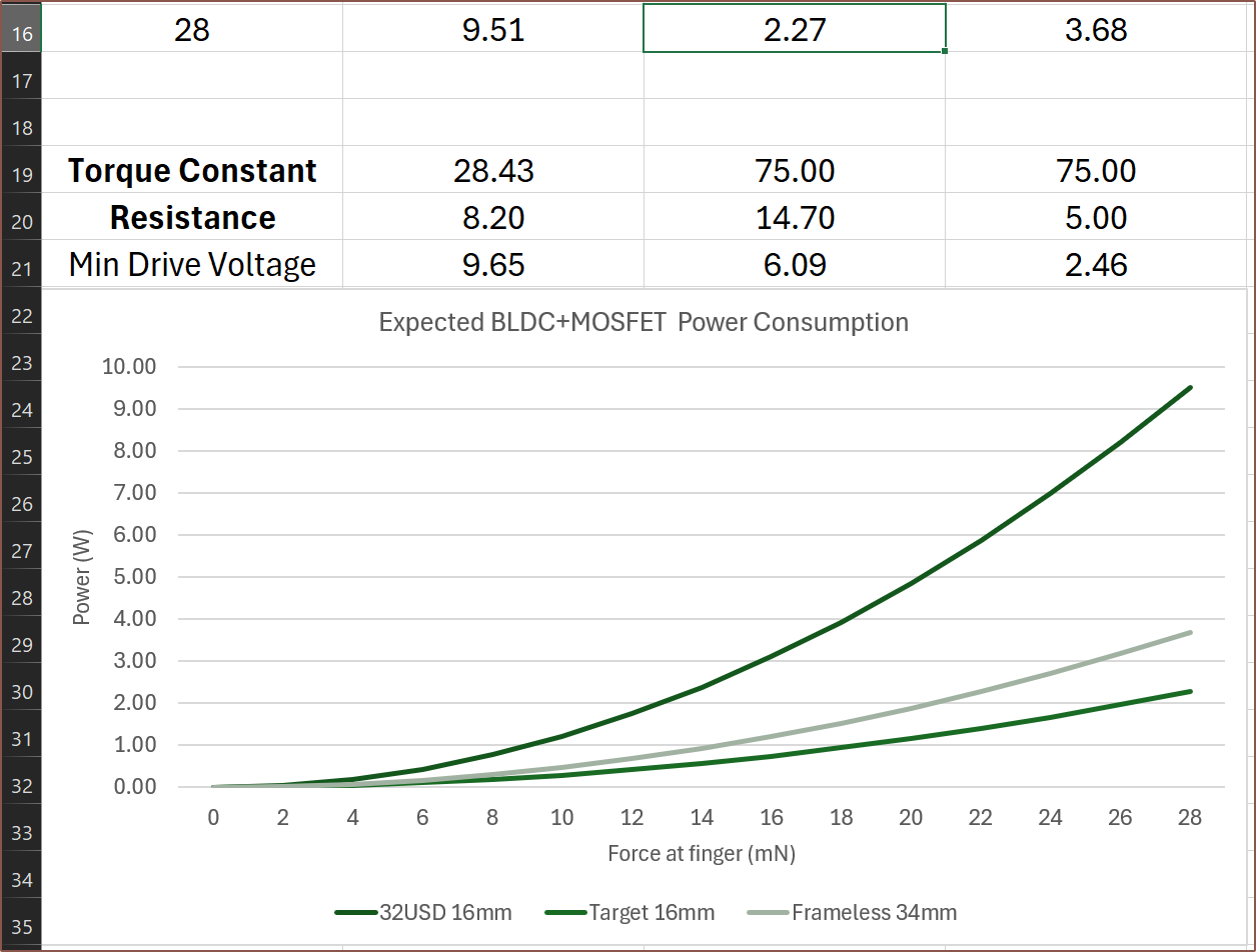
Doing some quick maths, it seems that this motor has a torque constant of 75mN.m/A. When generating 20mN.m of torque (to produce approximately the same force on the belt as the coreless motors below), it's expected that this solution will use 0.356W.
Slotless / Coreless
It doesn't have to be coreless/slotless, but it does seem that all the motors I saw were one of these types. It's beneficial though, since there's inherently no cogging for these types of motors.
I've seen motors as long as 59mm and as short as 36mm, and I believe that longer motors have a tendency to have better torque numbers. This is where those more-realistic torque requirements come in, as there isn't a motor that just happens to have 30nM.m of continuous torque.
For #Itinervate [gd0151], I believe that the enclosure thickness needs to be 24mm or less, which includes a 1.2mm top and bottom wall and 1.2mm of tolerance. Thus, the Tetrinsic to solve for this soluion needs to be 20.4mm or less, which might barely be possible with a 16mm diameter motor and double-sided belt. I think it's probably easier to aim for a round 1 inch (25.4mm), thus Tetrinsic would need to be 21.8mm or less.
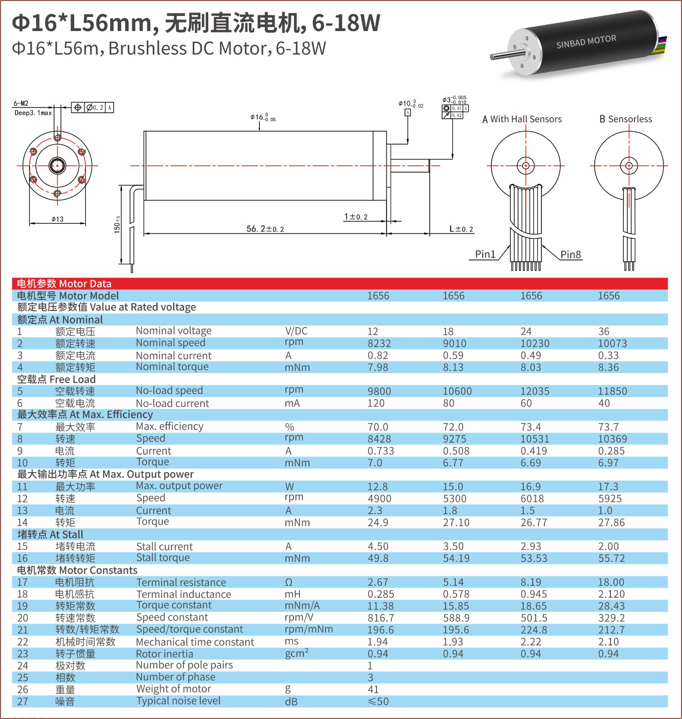
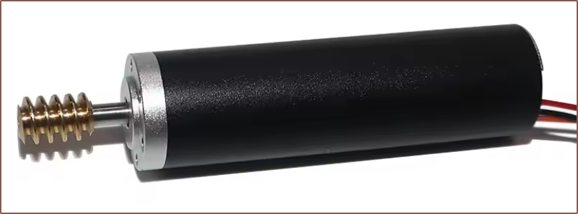
An ideal candidate I've found is this 1656 motor:
I asked, since the page also specified 2.67 ohms as a resistance, and they said that the phase resistance was up to 2.9 ohms.
Something to note is that the rotor inertia is 0.86 g.cm2, compared to 51 g.cm2 for the WK2806. Many other 16mm diameter motors had similar values, suggesting that it would be a lot easier for this form factor to produce haptic vibrations.
The above motor has the highest torque constant I've seen in my research, at 20.8 mN.m/A, suggesting that I'd need 480mA to get 10mN.m, resulting in only requiring 0.668W. On the other hand, if I provide 5V to the motor, a maximum of 1.72A will flow though the coils, producing 35.7mN.m of torque and consuming 8.6W. Other motors I'm finding can't seem to get that kind of power consumption when generating 10mN.m. For example, the 165603 BLDC uses 3.5W and it's shorter 164603 uses 5.9W.
Unfortunately, I asked about the price and the seller said it's $50/ea with "cheap encoder", and $34/ea without. It also has a brass screw which I don't need.
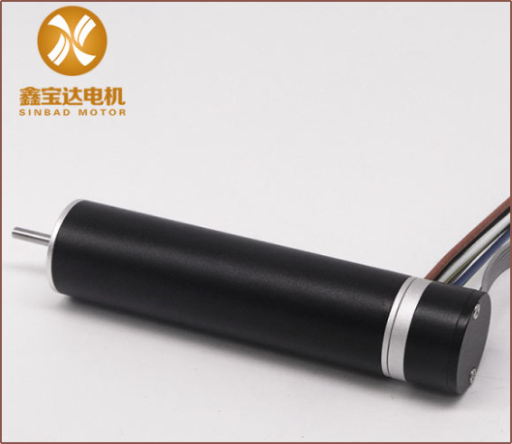
When I asked if there was a motor without the screw and with a high torque constant, the seller suggested another motor that is $48 with / $32 without the encoder.
Diameter: 16mm
Torque constant: 28.43 mN.m/A
Peak torque: 27.86 mN.m
Phase resistance: 8.19Ω
I predict it would consume 1.01W at 10mN.m. Its stall torque is 28mN.m and stall current is 0.98A, which is a beneficial factor if driven with the STSPIN32G4 (mentioned further below) that has a 1A peak current.
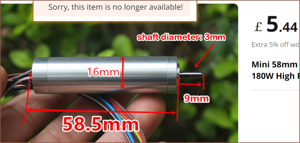
On AliExpress, there was a 58mm motor but it's unfortunately OOS:
[Apr30: Edit 4] It seems that this is the 1659RB from kegumotor, which is $65/ea when ordering in quantities under 100pcs:
[End of Edit 4]
Other motors I've found on Alibaba seem to all share a 3mm diameter shaft too, so I could use the S163A if geometry allows:
Speaking of gear's, I imagine that there's probably enough space for a 1:2 gear reduction between the bevel and output pulley, which further helps and means that I likely just need to look for a motor that has 50gf.cm continuous and >=150gf.cm stall. The output "pulley" might actually just be a large spur gear.
Making a slotless BLDC?
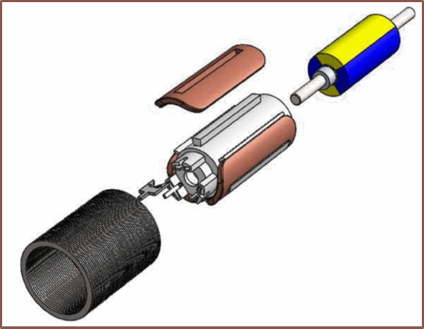
I've also found the paper titled Low-cost slotless BLDC motor designed for mass production, published in 2021, where it describes how to go about making a 19.4mm diameter slotless motor. 3 phases are wound on a plastic housing using 0.21mm wire:
I'm already mentally simulating how I could design a stator that can be wrapped with copper foil to increase the packing density.This is then encased in a cylindrical iron lamination. For the rotor, a 2pp magnet (chosen over 1 pole pair for higher torque) is glued onto a 3mm shaft, and there are bearings on either side. They provide an exploded view:With this, they were able to achieve the 75mN.m/A that the frameless motor mentioned earlier gets. It doesn't seem like they tested stall torque though, so that's still a mystery with this design.
A notable thing the mentioned is that overmoulding is not needed to prevent liquids from touching the coils. This is important in their application because this motor is for a fuel pump. It's important for Tetrinsic as it means that water resistance could still be on the cards.
One slight drawback they mention is that their motor needed to be slightly longer than the reference slotted motor, but that's not an issue in this application. I'm planning for a motor around 100mm in length.
STSPIN32G4, the chip that could do it all?
K(at)B had also suggested the STSPIN32G4, a 128KB flash chip that could potentially run everything from hall and FSR A/D conversions to BLDC FOC output in a 9x9mm package. As I've learned from creating the first Tetrinsic PCB, traces and vias are far from negligible in size, and thus multiple chips will take up more area than one larger chip.
I thought that the min supply voltage was a bit low, but I forgot that any BLDC controller would have its own resistance, and it seems it's in the range of entire ohms. Since power = voltage * current, and the max available is 1A, it means the power is directly proportional to the lowest voltage the motor can run with. If I aim for a 6V motor with a 1A peak, I'd need the phase resistance to be sub 4.4 ohms. The $32 motor would be driven at 10V (9.6V plus unaccounted-for resistive losses).
Conclusions
At the moment, the frameless motor solution is almost a solved problem, but the 16mm motor situation seems a bit shakier. However, I also have to keep in mind that the frameless motor would have cogging to an extent that some kind of algorithmic nullification would be needed.
For Tetent, the idea using the frameless motor is to go back to the tightrope design, but this time CNC-mill a track (instead of trying to deal with tubes, printed parts and the flexible nature that arises from them) and then stick these nifty 160pixel/m LED strips on the underside:
Then, a LS032B7DD02, 3.16" MIP LCD would be used so that I get the cool animations whilst not sacrificing power (thus it's more likely to actually be kept on), especially in office-lit, window-lit or outdoor environments. The active area of the LCD is a bit shorter than I'd like, but I can just slope the inner walls so that the active length of the Tetrinsics (which is about 50 - 60mm) isn't reduced because of it.
I expect that a custom Tetrinsic would have to be designed for the thumb. If using the slotless strategy, the motor would be in the same orientation as the finger Tetrinsics (so no bevel gears needed), allowing for a hollow interior so that they can fit though. Because of this, it might make sense to try and keep any gear-train as close to 1:1 as possible.
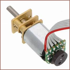
For reading the motor orientation, I'm likey going to use a diametric magnet on the shaft and 2 hall effect sensors oriented 90 degrees, which seems to be the way it's done on 6V brushed motors with encoders:
At the moment, I can only imagine a solution for using the FSR for the slotless strategy since it can be placed directly under the belt and held in place with double-sided tape. Unlike the frameless strategy, I wouldn't need to counteract the force due to the weight of the track with a BMI160 accelerometer, nor would I need the 24-bit ADC. If the flash size isn't an issue, this whole project could potentially run out of the STSPIN32G4.
In terms of commercial offerings, that one $32 motor is the most fine-tuned for this strategy. However, if I want to try for lower costs and power consumption (and thus heat dissipation), I'm going to need to research into iron laminations and rotor magnets to see if those are available at low cost. If they are, I may go down the path of a custom BLDC motor. I'm slightly more concerned about the iron laminations, as I probably could just stack shorter polepair magnets into a longer one. On the other hand, it seems that the reason why the iron is laminated is to reduce current losses. Perhaps it's possible to use a material where iron is suspended so that it increases magnetic permeability without being conductive, such as the "magnetic iron PLA" used in this 3D printed motor.
Power consumption with the 1.6ohms of the MOSFETs inside the STSPIN32G4, is expected to be the following:
The title is a play-on-words of GAAFET, standing for Gate All Around, Field Effect Transistor.
Now that the #Coaxial8or [gd0144] is in a bit of a break period as I wait for the new heatblock design to be fabricated and arrive, I have been looking into Tetrinsic again. I still feel like if I had to choose 1 single project to "get past the post" (i.e. design, manufacture and implement into my daily life), this is it; unlike 3D printers and XR glasses, I unfortunatley haven't found enough information on the internet that suggests that some company would come out of "stealth mode" with a sufficient offering, and even if one did come out today, they'd most likely say it will start shipping "in months" but implications would mean that "in years" would be more accurate. On the other hand, I haven't been able to indirectly find this project through my search queries, so there could still be similar projects and solutions that I haven't come across yet.
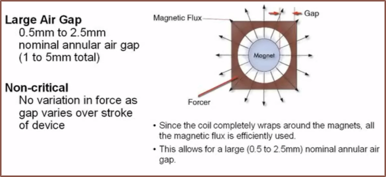
Anyway, I came across this video about linear shaft engineering:
My strategy I thought up back in September 2023 was the U-shaped linear motor, just with the coils and magnets swapped around. This aleviates the cooling drawback they mentioned, but understandably still has the drawback they mentioned where only half the magnetic flux generated by the coils used (the other half is in the opposite direction).
The video states:
Force (N) = Current (A) x Magnetic Flux Density (T)
Thus, for a fixed current, more force is generated with a higher density. This also suggests that, for this application, it's better to drive the system with as low a voltage as possible.
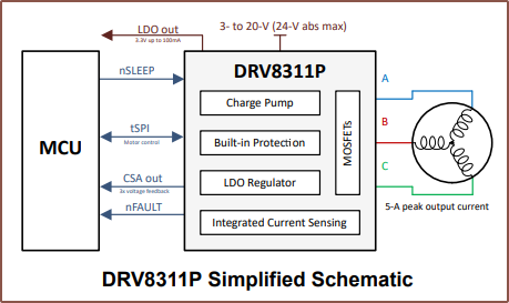
Looking into the DRV8311, they're just simple H bridges at the end of the day so it's not like the chip is doing anything fancy with the input voltage. Additionally, I found these answers on stackexchange. While doubling the voltage will double the torque, it would quadruple the power required. Thus, since the power for each Tetrinsic is limited to prolong battery life, and I mainly need the torque in very low - low speed situations (e.g. sub 300Hz haptics) higher voltages are actually worse, as are very thin (0.1mm) wires used to make the coil. Instead of 12V, it now sounds like it would make more sense to run everything on 3.3V, which would still allow for up to 16.5W per Tetrinsic.
Additionally, I've read bits and pieces that should lead to improved performance, but this answer brings everything together. For example, it did seem that a thicker magnet would increase strength when reading Doubled Forces, which the user "cinaral" confirms. They also say that the thickness of wire -- thus its current carrying capacity -- roughly balance out with the amount of turns that can physically fit in the space, which sounds like a foil coil is still the more ideal strategy from a heat dissipation and manufacturing standpoint.
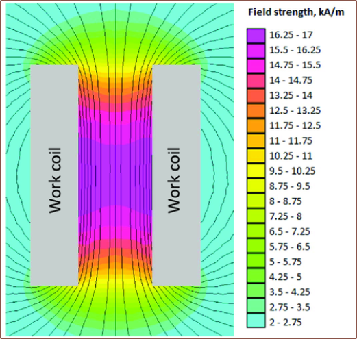
As mentioned in the video, magnets emit their field in all directions. What wasn't mentioned, but probably just as important, is that the coil has it's highest flux density in its centre:
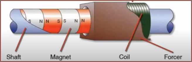
It likely is also so that the shaft doesn't just act as one massive magnet. With this in mind, the plan is to move from a 10x3x2 to a 10x3x3 magnet so that I can place them in this configuration.
Manufacture
I already knew about linear shaft motors (but not their benefits over U-shaped ones), but the issue is that I still need to actually make a belt or a motor or both. With the U-shape solution, both of these can be made separately, wheras with a coil-all-around solution, one would have to be made in-situ.
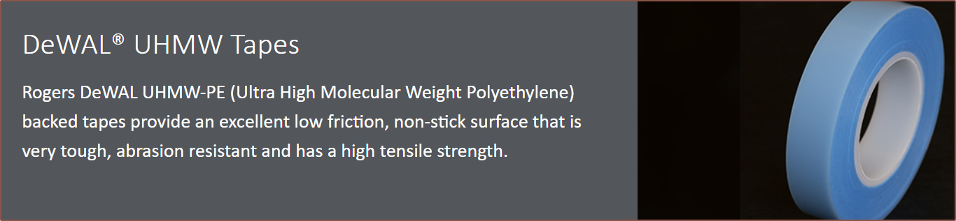
Additionally, I need to consider how individual magnets will come together to form a belt in the first place. Since the magnets are relatively small and the belt also needs to slide across the stainless steel tubes with as low friction as possible, a potential idea is to stick the magnets to UHMW tape which acts as the belt, which seems to have all the features I would need.
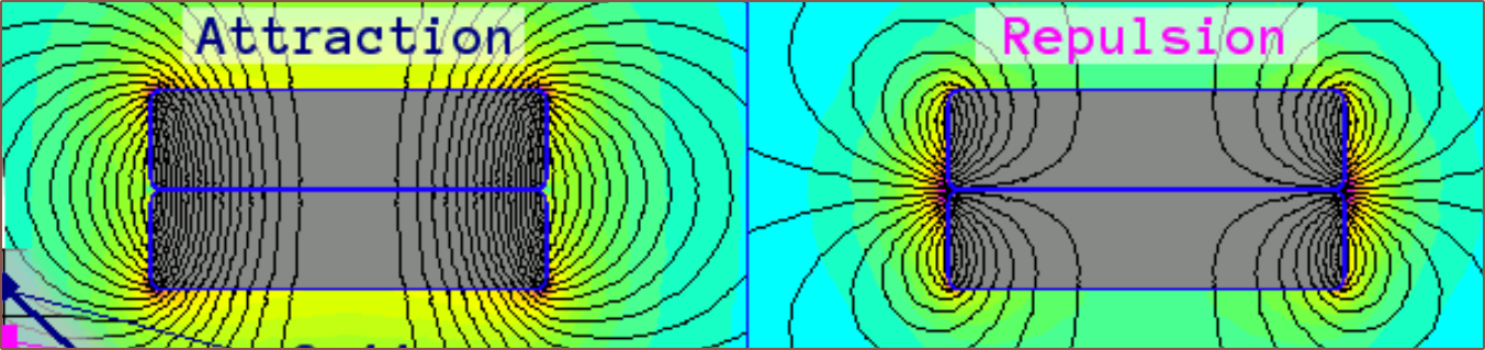
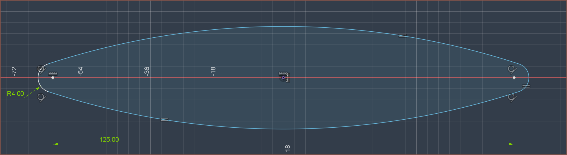
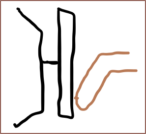
The main concern is that, due to the repulsion forces of the magnets, the flat sections of the belt are expected to inflate outwards like this:
Each magnet will also be trying to push away at each other with up to 700g of force, though that number is likely to be closer to 500gf, which likely will increase the fabrication difficulty. The benefit is that the minimum turning radius can likely be small.
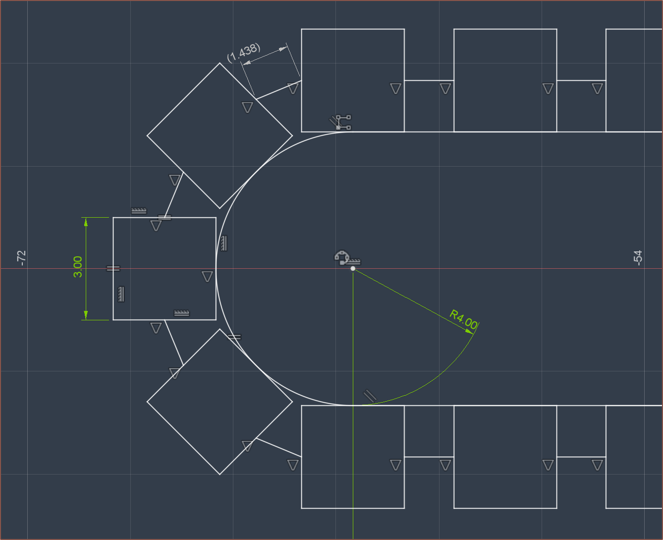
Another solution is to tape both sides so that the living hinge is in the middle:
The benefits are that the straights are flatter and the gaps and the potential to use a grippy outer tape will reduce finger slippage. The drawback is that the magnets are spaced further apart (potentially reducing max torque) and the minimum turning radius is more limited (both due to geometric limits and because the repulsion force will be much stronger on the side closest to the pulley.
It's likely still possible to go with the 3D printed vase-mode strategy, whereby a case for the magnets is printed in TPU. In this case, the coils will have to be wound around the belt (thus I won't be able to outsource them).
 kelvinA
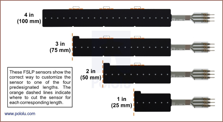


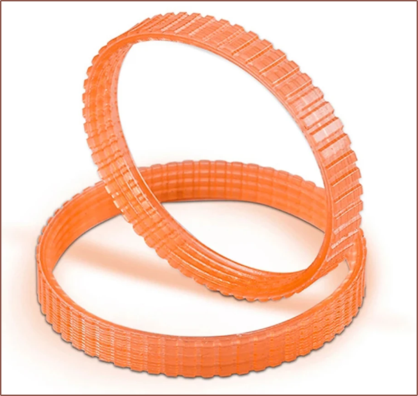
 It also seems self-centering, meaning that I wouldn't need the flange and so I could probably tweak the gears to use something like this:
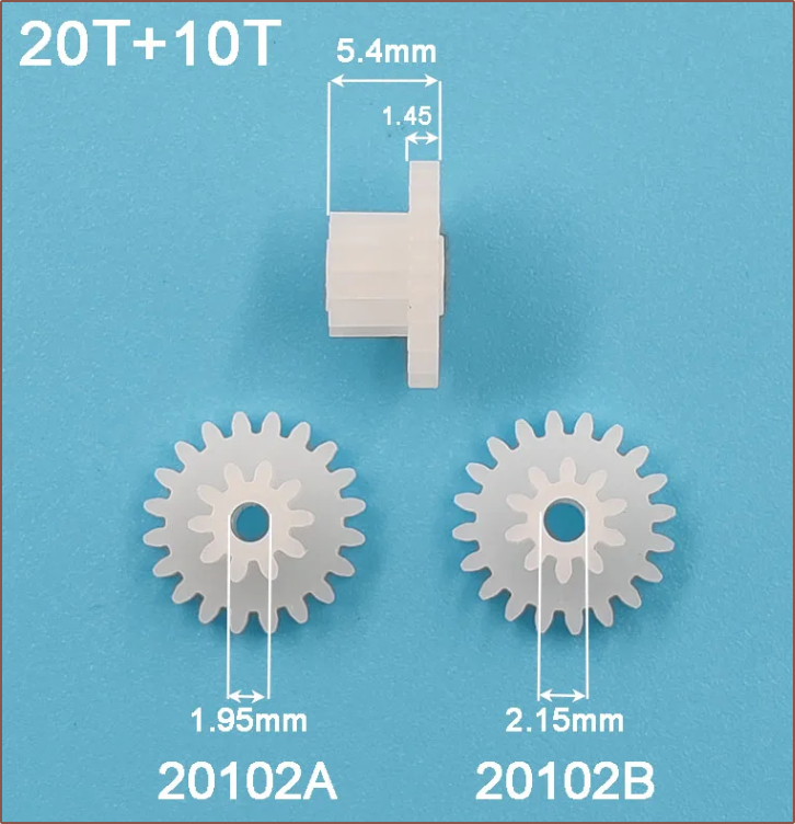
 You might be wondering what this is. This is the approximation of 3mm copper foil stacked on itself. Since copper smaller than the magnet width does not provide any torque (so I've heard), it makes more sense for the tape to hug the edges.
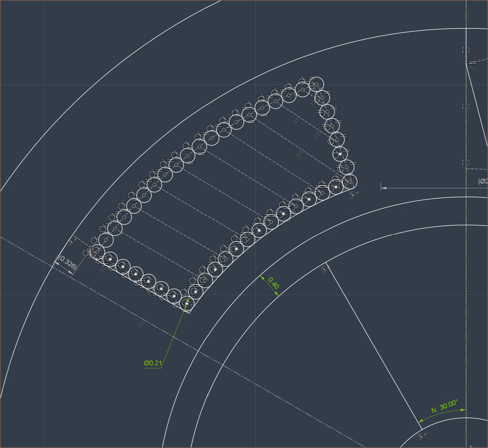
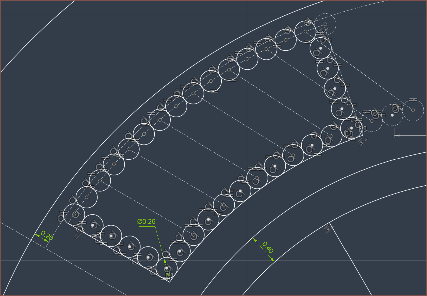
 This is what I expect the "overmould" (as the paper calls it) would look like. It seems that I now just need to find a way to aquire a 3-pole-pair magnet ring for the stator. On the other hand, it sounds like the paper highlights that magnets with higher pole counts are more sensitive to the air gap. This kind of makes sense if I imagine that they're separate magnets instead of a single multipole magnet, whereby the field lines would extend a shorter distance if the separate magnets were smaller.
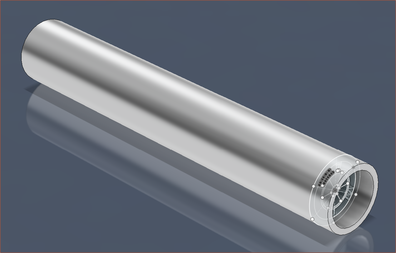 100mm might actually be a tad on the long side, considering that the pulleys + belt would contribute about 40mm to the total length alone, along with another 10mm just for the bevel gear.
 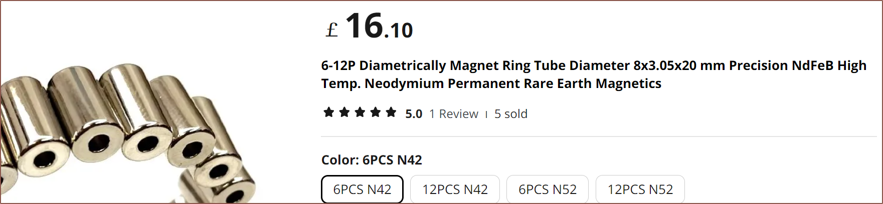 The slotless paper had a breakdown of normalised prices, and the magnet for the rotor was 52% of the entire cost, so I was expecting that it was going to be rather costly. I also found 16*12*9mm ferrite rings that are a tad bulky on the wall thickness:
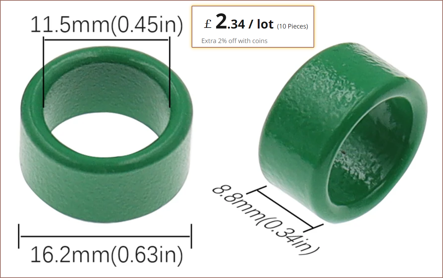
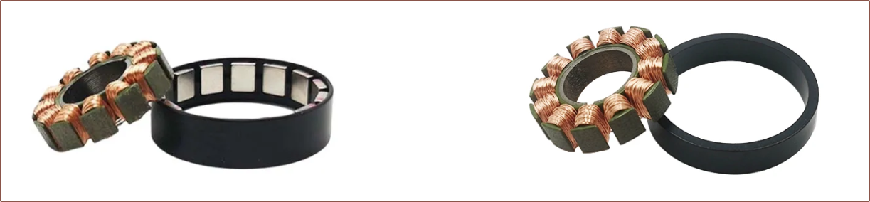


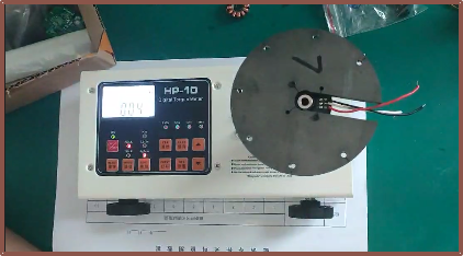 The torque metre recorded a max torque of 0.04kgf.cm, which corresponds to 40gf.cm and thus 20gf on the belt, which is on the lower end of scroll wheel encoders:
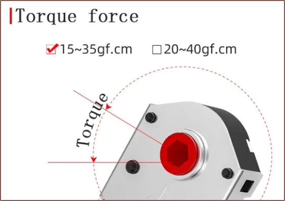 It's expected that the ring magnet would have even lower cogging.
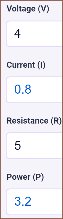
 With this, they were able to achieve the 75mN.m/A that the frameless motor mentioned earlier gets. It doesn't seem like they tested stall torque though, so that's still a mystery with this design.