If you are working on a similar system, here is a link to the GIT Repository for my Marlin. I went with a Clone as opposed to a Fork. I'm only planning to apply hardware specific changes and once the printer is working as desired, not update again. That is unless something AMAZING is added to Marlin.
0%
0%
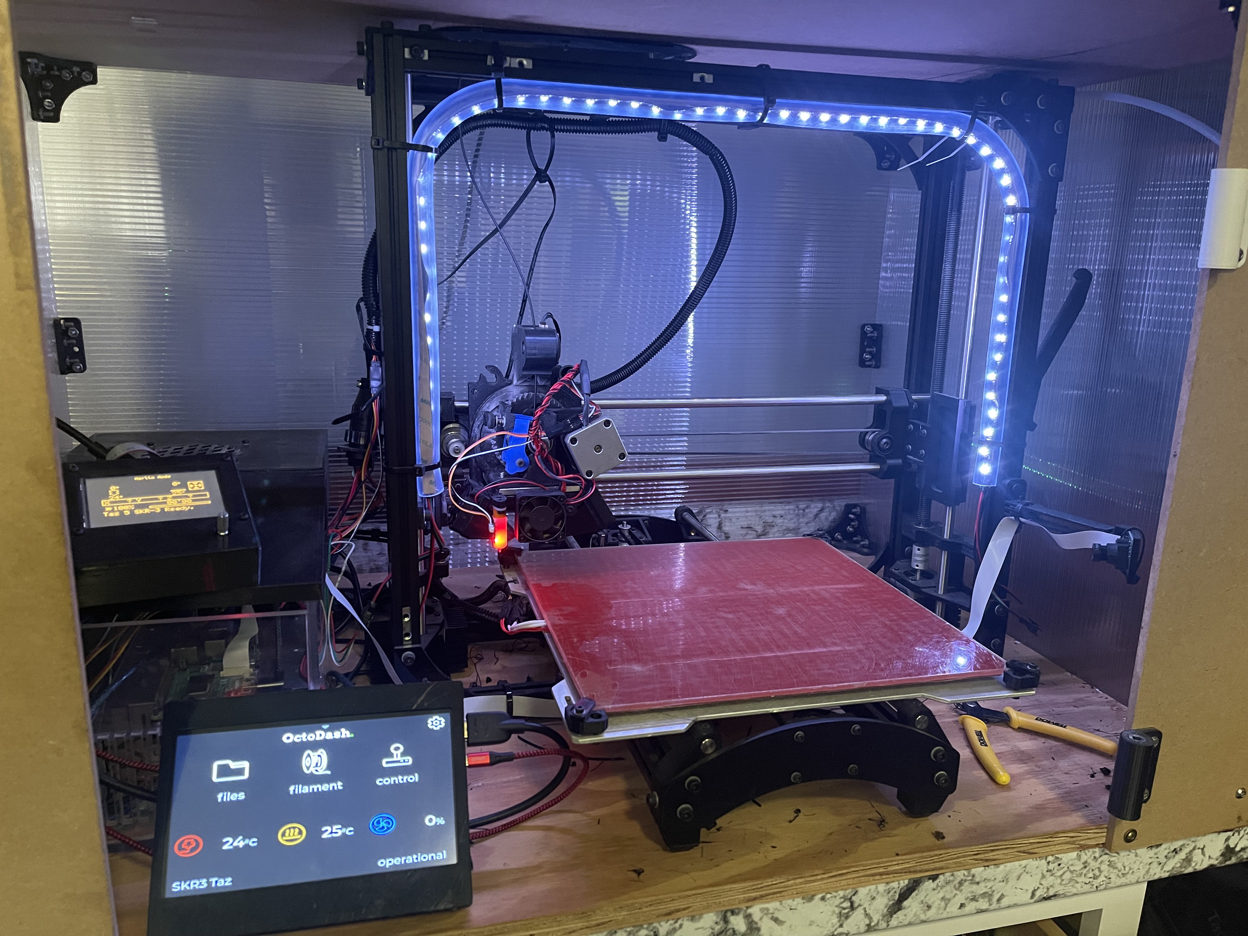
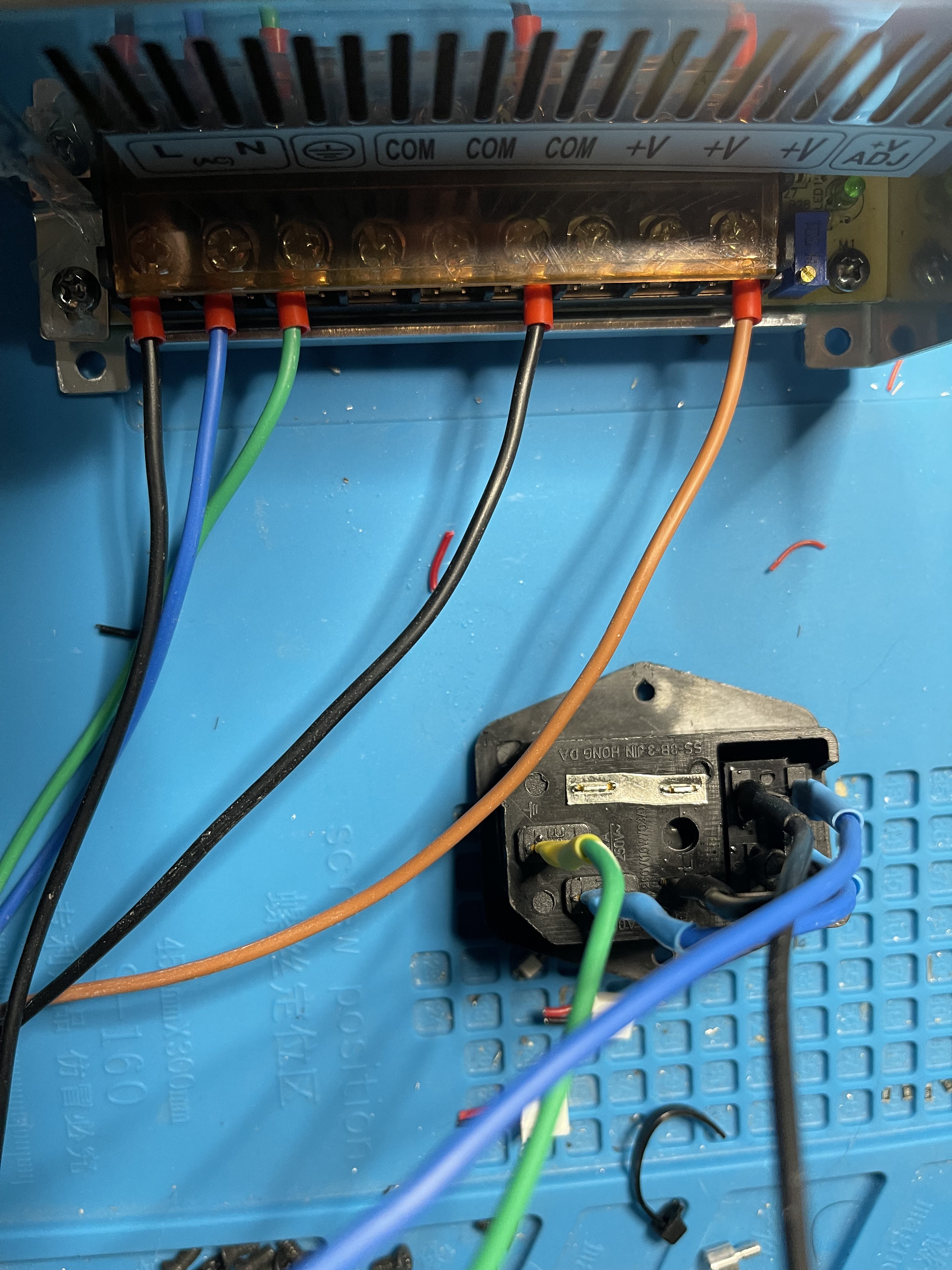
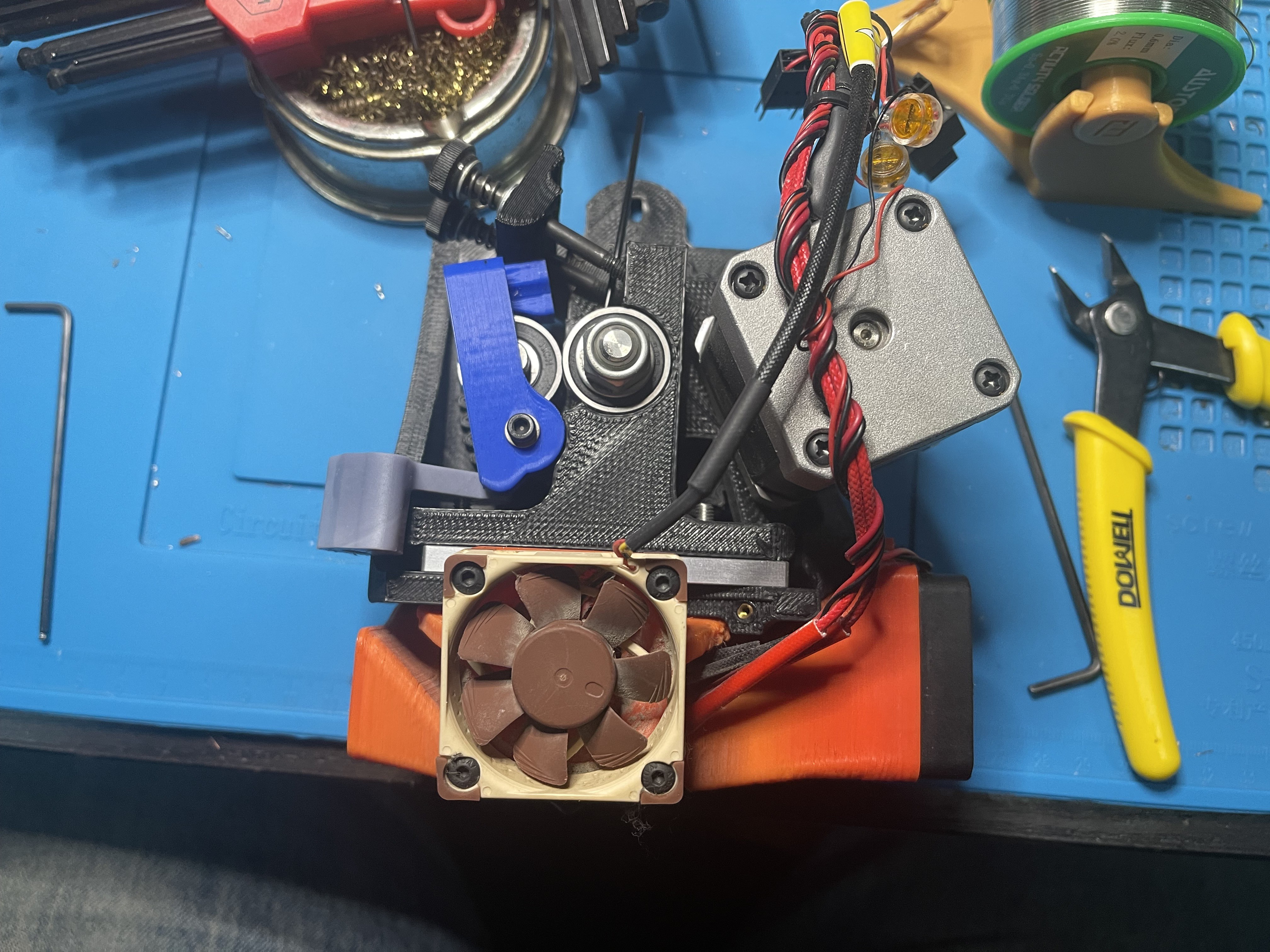
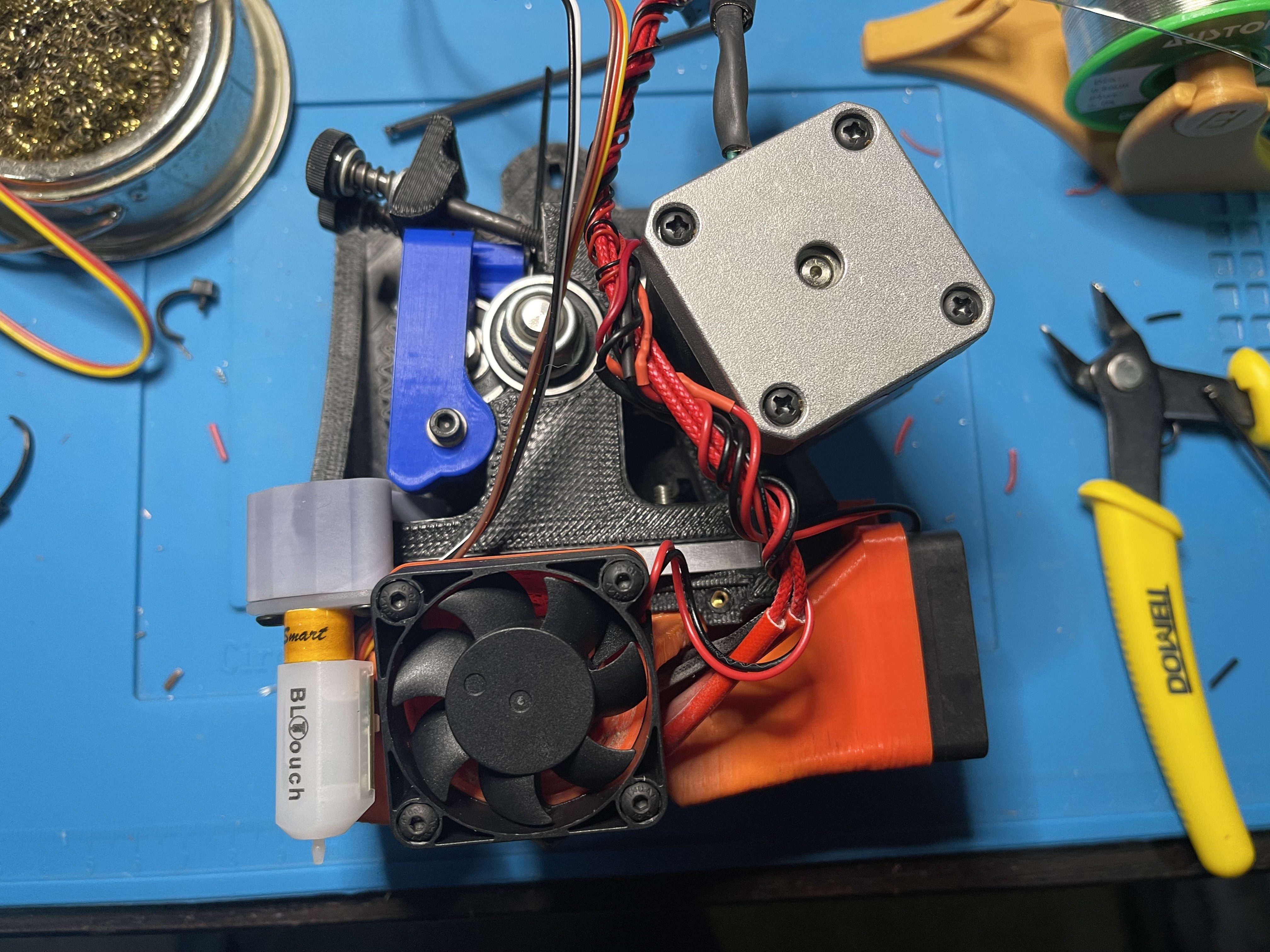
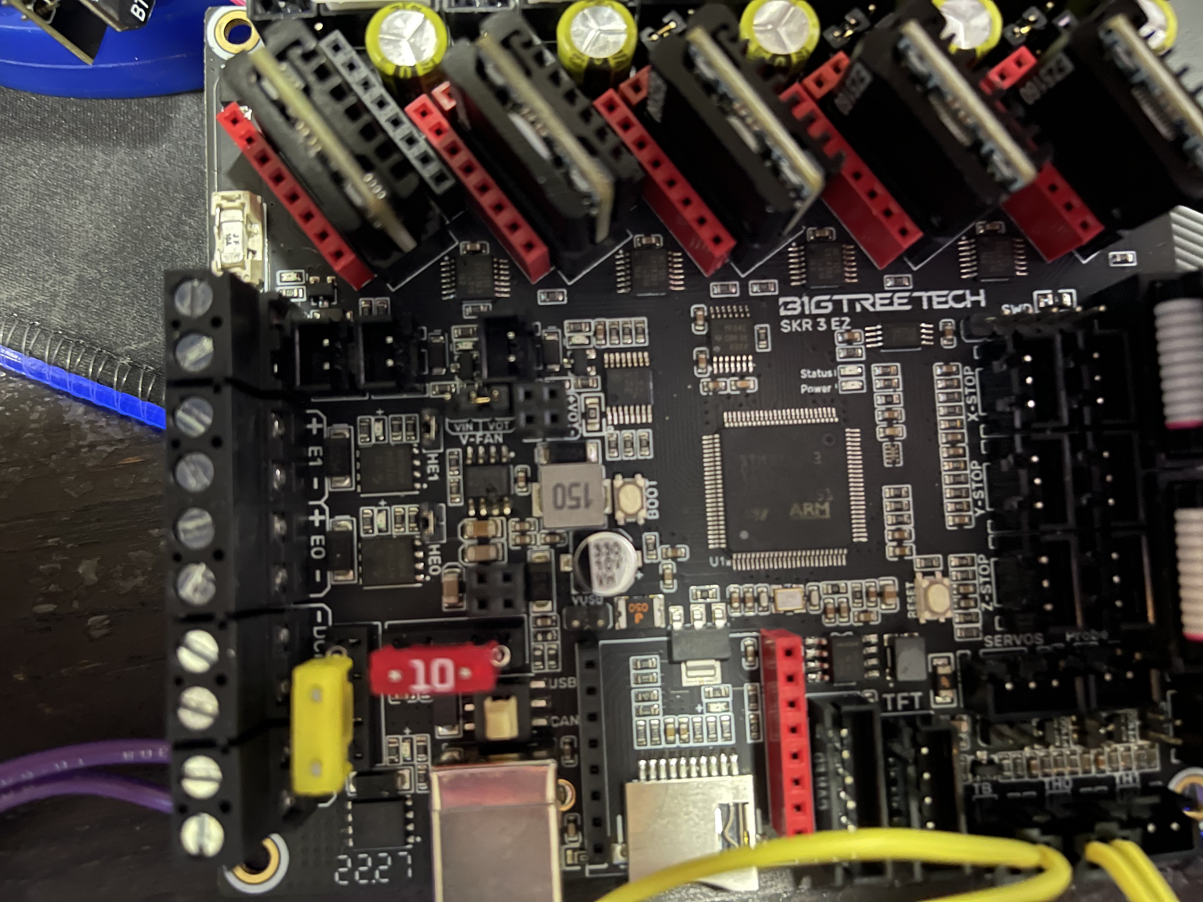
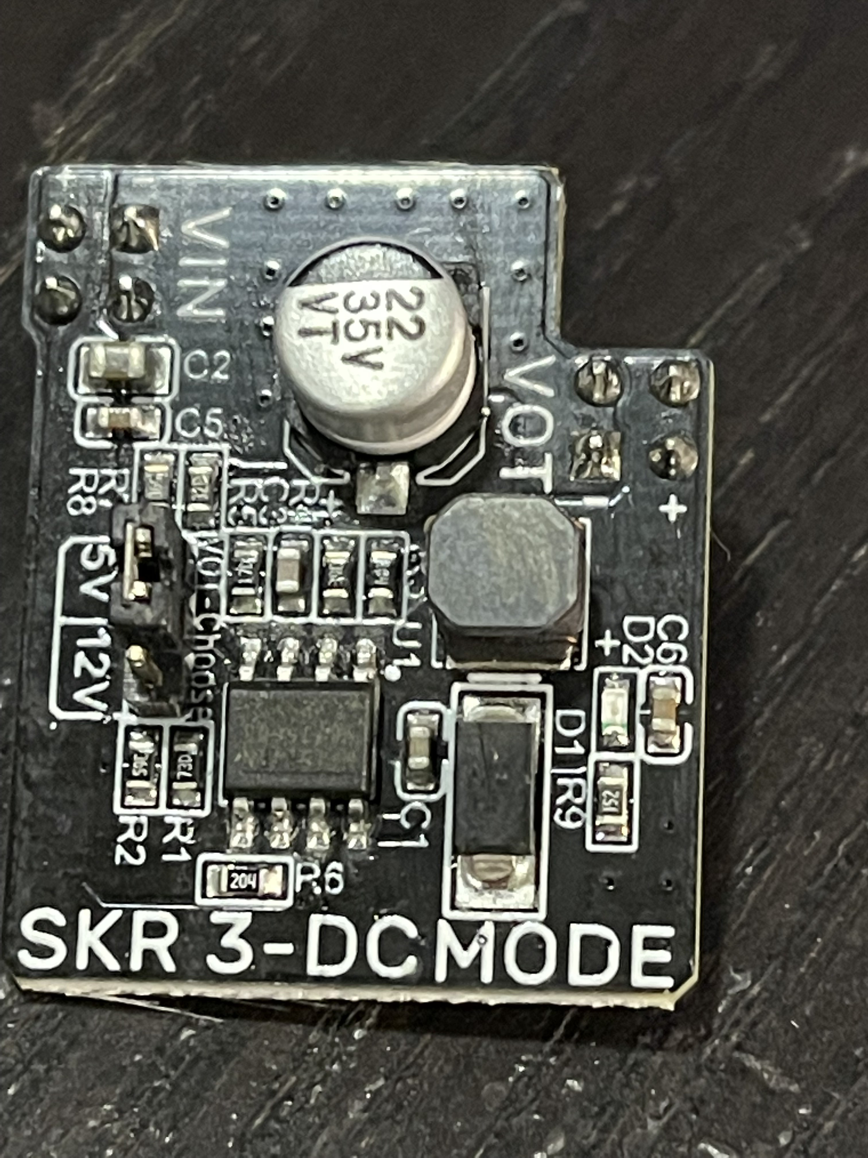
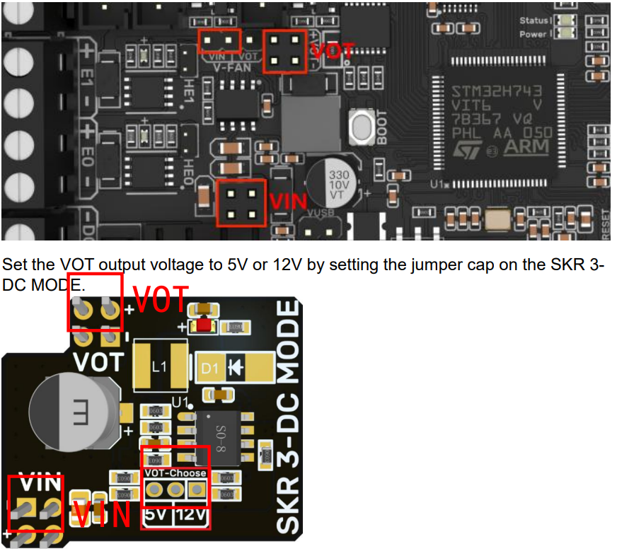
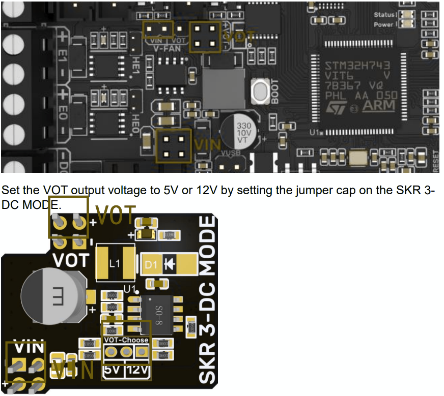
Taz 5 BTT SKR 3 Refit
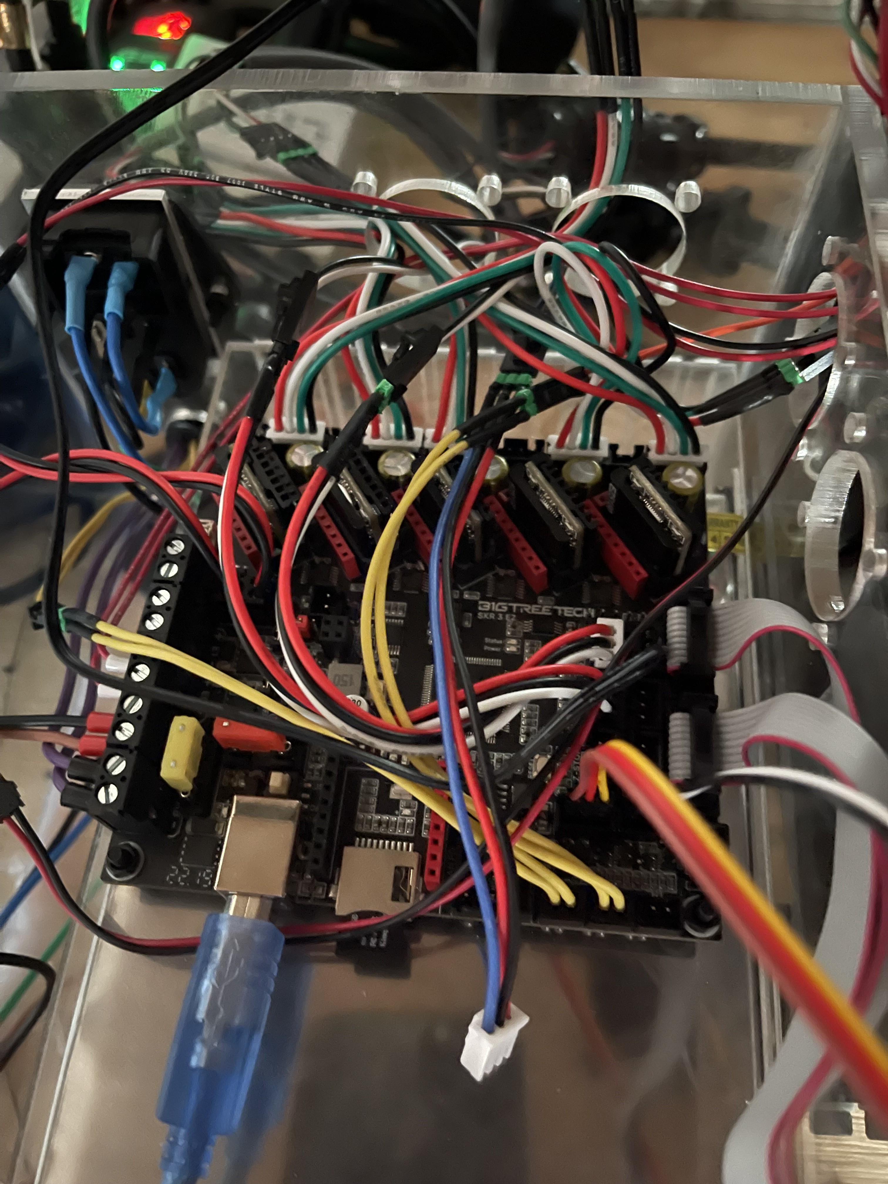
Lulzbot Taz 5 rebuild with a BigTreeTech SKR 3 and 5160 Drivers
Become a Hackaday.io member
Already have an account? Log in.
Just one more thing
To make the experience fit your profile, pick a username and tell us what interests you.
Pick an awesome username
hackaday.io/
Your profile's URL: hackaday.io/username. Max 25 alphanumeric characters.
Pick a few interests
Projects that share your interests
People that share your interests
 core weaver
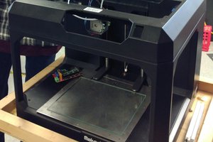
 Thomas Bladykas
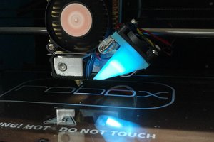
 Rob Ward
 Matt
Matt
I switched to a BTT Octopus board with BLtouch and Klipper and Hemera Evo, it works beautifully.