 Fulvio
During lockdown, we've started to study how to build a little solar tracker to charge powerbanks, smartphones or run small fans.
Existing projects use servos (for little solar panels) or linear actuators.
We've found some limitations in projects that use linear actuators:
- big/heavy infrastructure to support solar panels
- they often make use of external batteries to carry out the movements
Here our new approach:
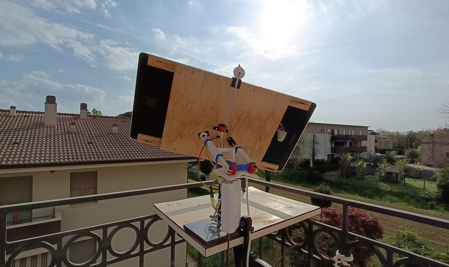
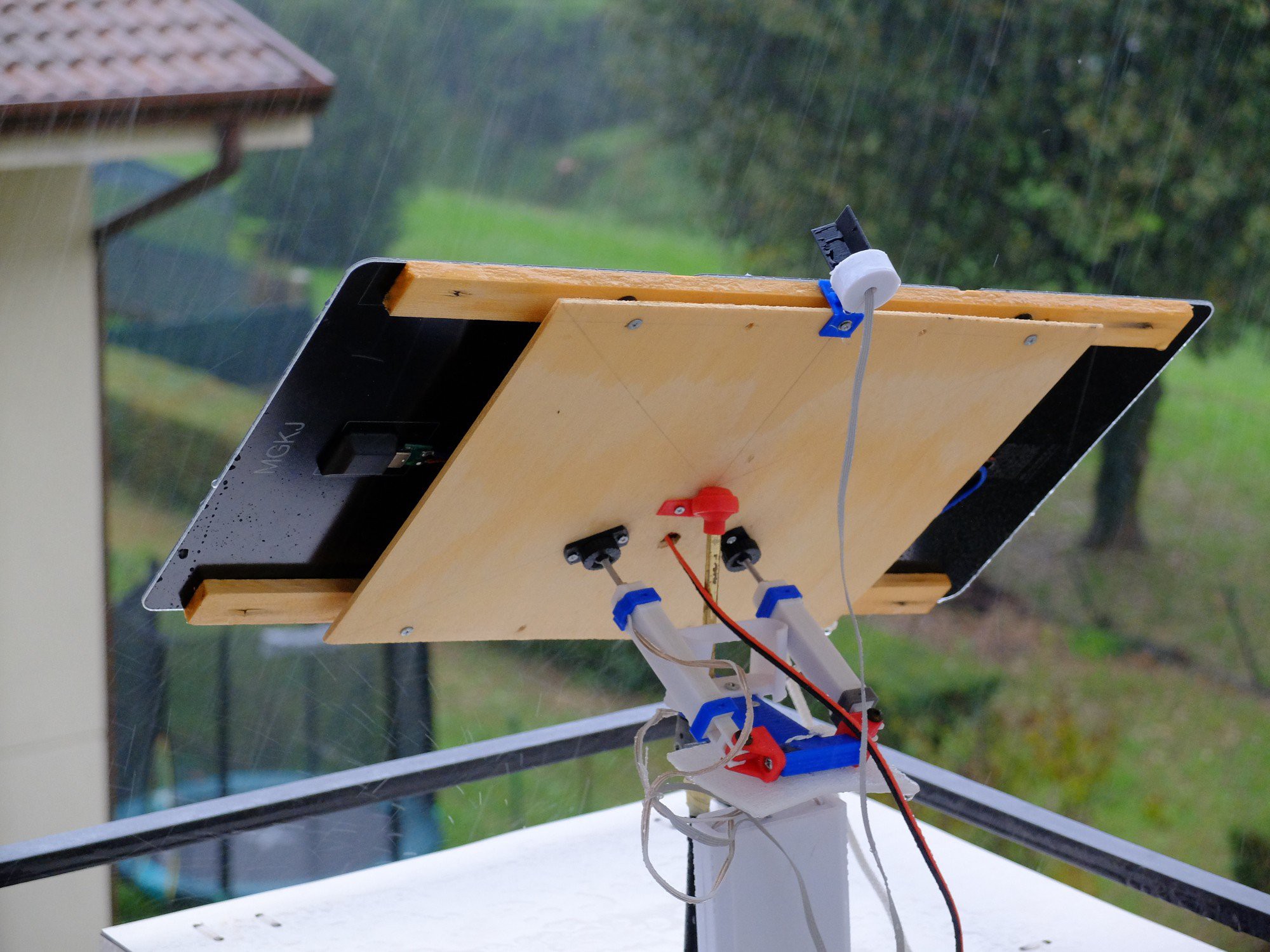
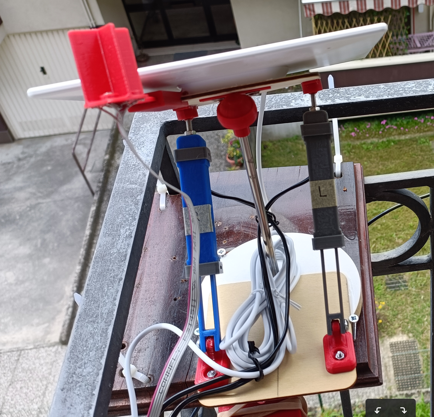
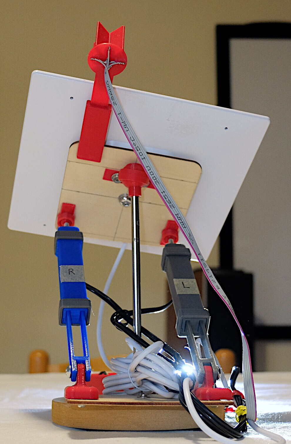
- the solar panel gain three support points, we think will be more sturdily and wind resistant
- the panel can be moved to hook sun during the day where the sun gives off more energy
The two-more support point are realized with actuators, they can be placed both on the base or hooked to the pole that supports the panel (like the example).
There are some challenges we want to address:
- build cheap actuators
- build new actuators with a kind of waterproof
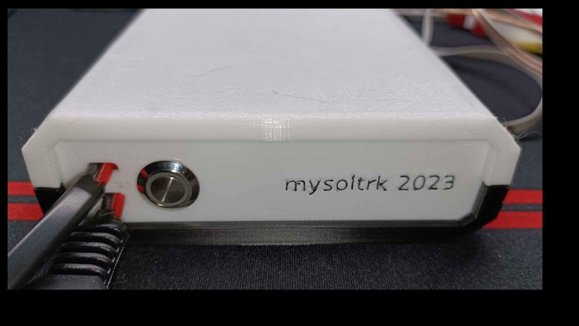
- build a low power board that not use any kind of battery (use only energy from panel)
- do it all on a low budget
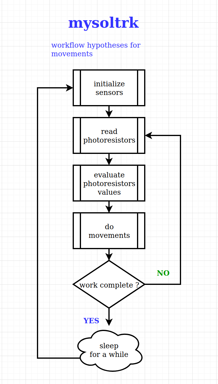
- write a software from scratch to implement new algorithm for movements
Logs published in date order:
- A little linear actuator
- The construction - part one
- The construction - testing movements
- The construction - part two
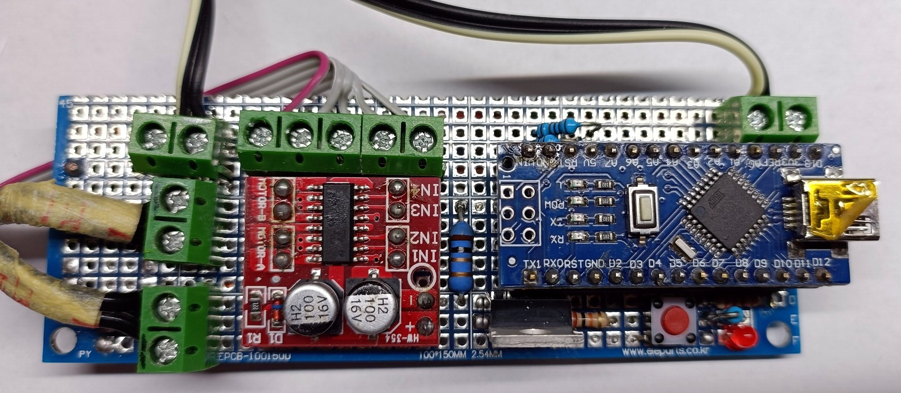
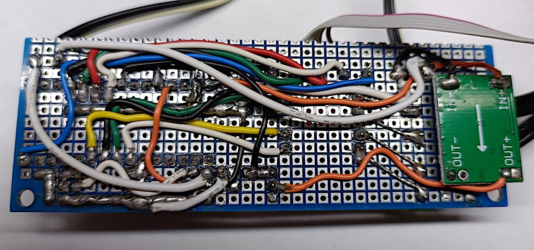
- The construction - designing the brain of mysoltrk
- Software design: transform an idea into real movements
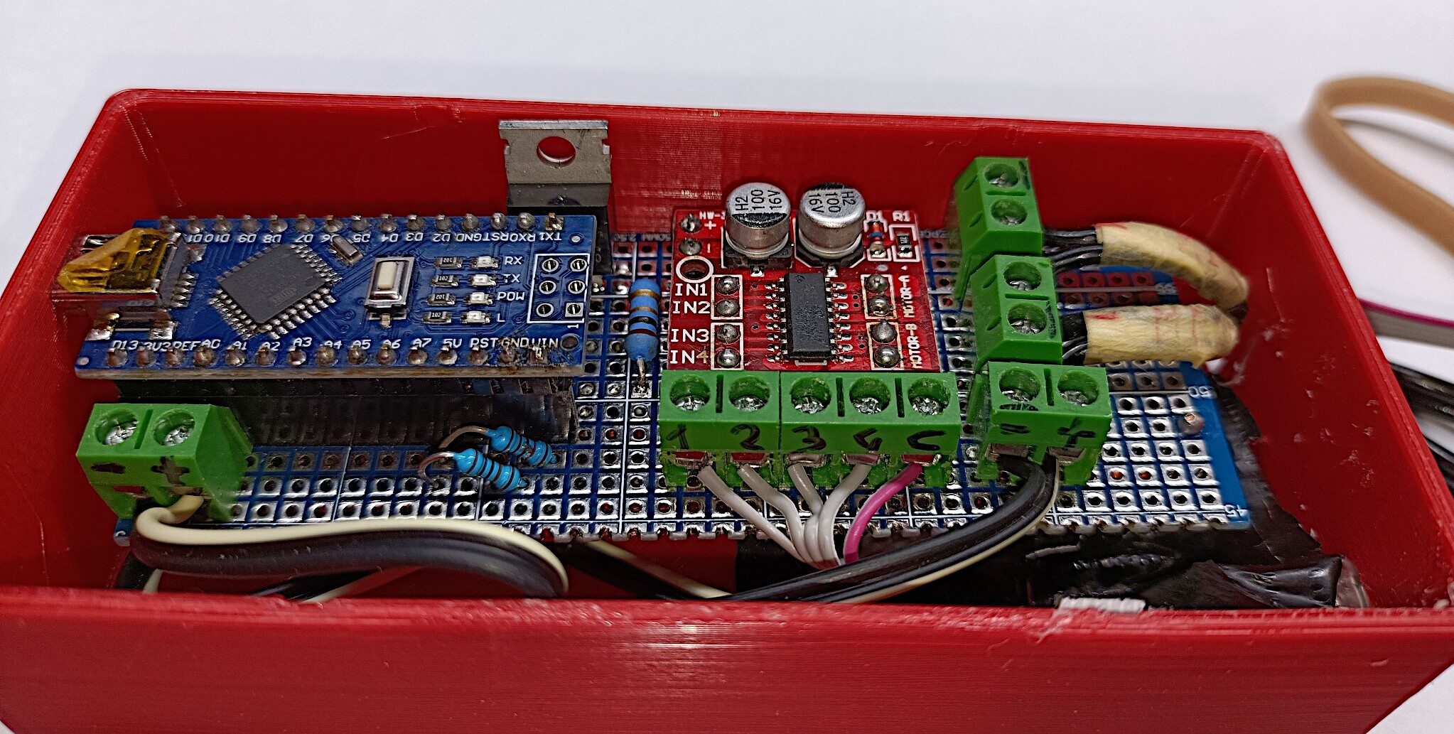
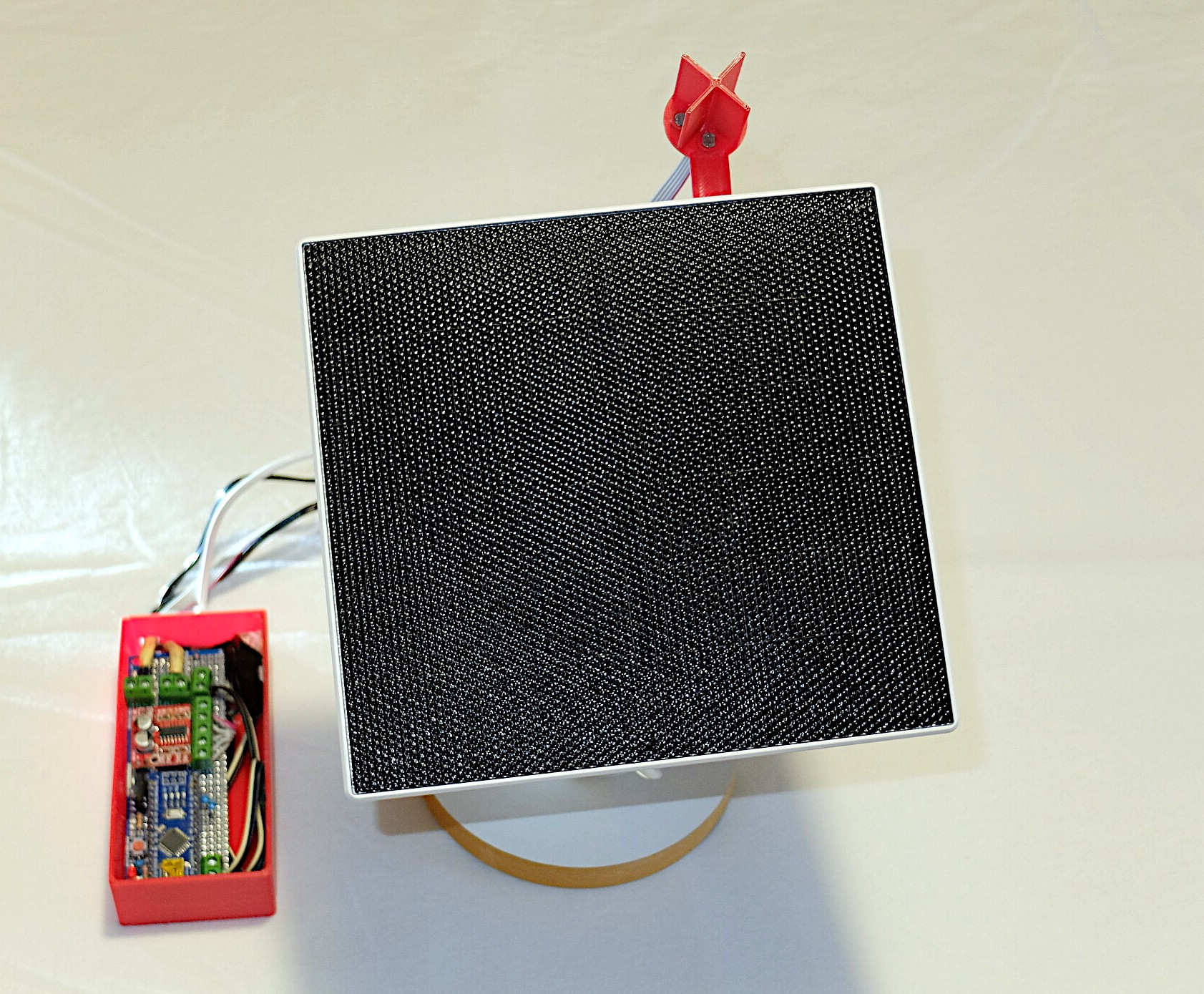
- Ready to go outside: the assembling
- Let's go outside to find the sun - first test
- Software design: work in progress
- In search of the sun: software test in the field
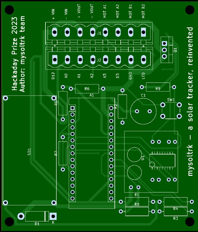
- From prototype #2 to #3: here is the PCB board
- Prototype #3: PCB completed
- The final report
- No news .. good news!
- Winter is over..


 Yevhenii
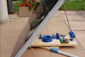
 JP Gleyzes
 Dylan Bleier
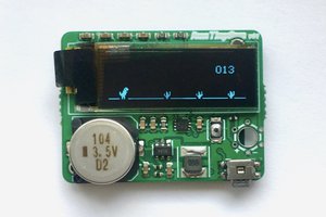
 ridoluc
What kind of sensors are you going to use to measure sun light power ? Or in other words, how are you going to decide how to move the solar panel to get max power ?