Fulvio
-
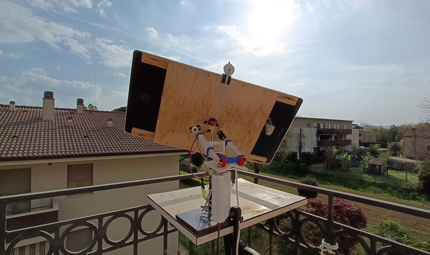
Winter is over..
04/05/2024 at 15:25 • 0 commentsHi everyone,
It's early spring and the prototype is still outside chasing the sun!
The bad weather ruined the plywood a bit but the circuit and the engines withstood the rain and cold.
From a mechanical point of view we had to:
- replace a damaged nut (inside the actuator)
- replace the collar that supports the panelsduring the winter, when the sun was available, we were able to charge a power bank, which is proving to be a convenience!
![]()
-
No news .. good news!
10/30/2023 at 11:00 • 0 commentsHi, mysoltrk is completed, but it doesn't mean that we are not continuing to work on the project.
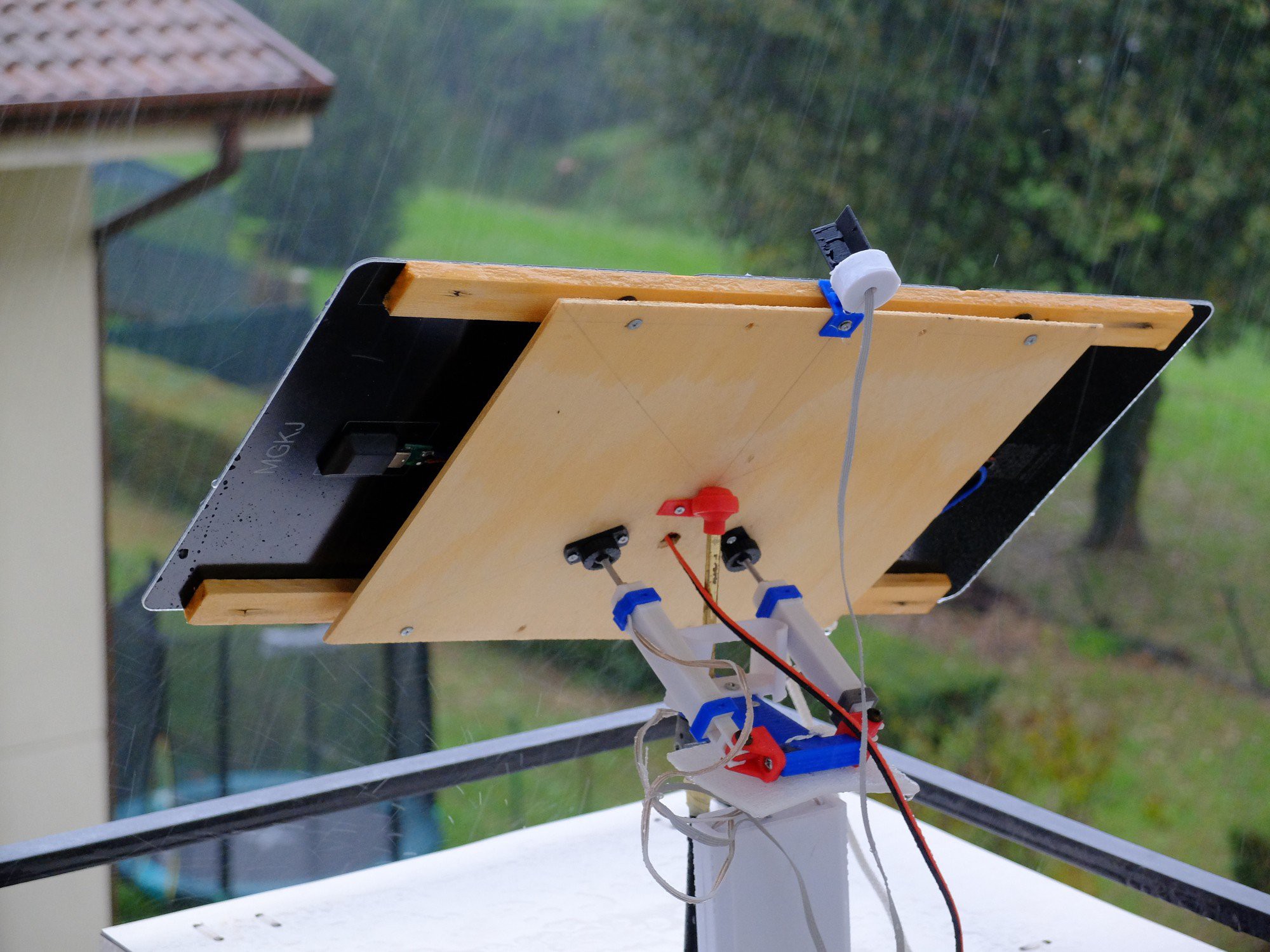
We are preparing for winter, so as to test the hardware even in adverse weather.
In the country where we live now it is autumn, and these days the rain is abundant:
![]()
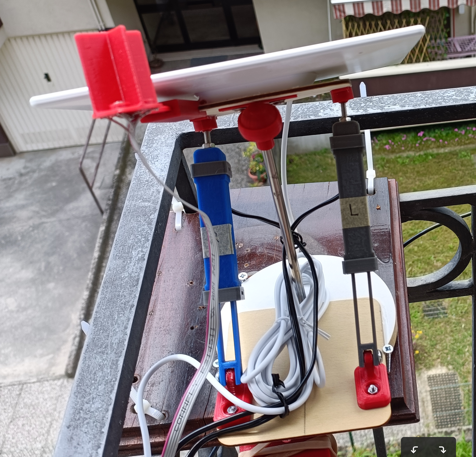
In this (wet) photo you can see another prototype, built around three panels 6W 5V monocrystalline panels put in series to provide 15 volts.
We verified that after a heavy rain, the panel turned toward the sun on its own, a sign that the circuit is working and well protected.
The other thing we noticed is that the angle of the panel is lower than a month ago, a sign that the viewfinder and photoresistors are correctly following the sun and doing their job properly
-
The final report
09/29/2023 at 14:39 • 0 commentsHello everyone!!!
Finally we can share the latest tests with the new solar panels.
Thanks to the PCB board, we are able to quickly build the mysoltrk devices.
The outdoor tests focused on the strength of the actuators and reasonable weight/size of the panels to be used.
In addition, the tests showed that the design can be put outdoors without worrying about weathering.
Here our video published for the contest. We hope you like it.
-
Prototype #3: PCB completed
09/15/2023 at 08:05 • 0 commentsHi everyone, we have completed the assembly of the PCB:
![]()
WARNING:
To avoid burning out the circuit, set step-down output to 5.0-5.2V before to mount to PCB !
(and secure the screw with a bit of glue)For this purpose, please use an external power supply as the input, with a voltage value similar to the solar panel being used.
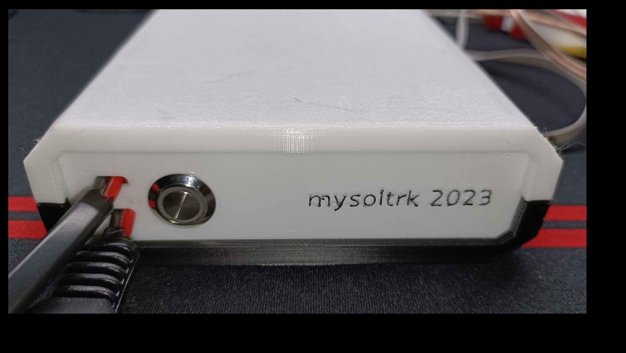
We also prepared a box, the whole thing looks professional to us :)
![]()
We are busy to build two working prototypes, with two types of solar panels.
We will update you in the coming days.
-
From prototype #2 to #3: here is the PCB board
09/01/2023 at 10:08 • 0 commentsHi everyone!
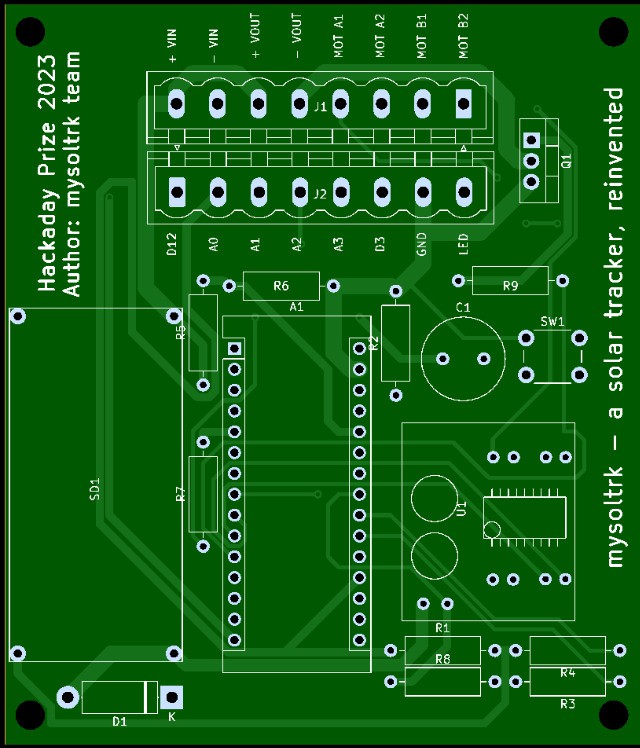
We have completed the development of PCB board, here the result:
![]()
You will find Gerber as usual in "Files" section.
We will show you the result as soon as we get it home.
-
In search of the sun: software test in the field
08/21/2023 at 19:53 • 0 commentsFinally we are ready to present the development result of the last month:
![]()
But, before continuing, we want to thank the jury for choosing our project.
This is further motivating us. Thank you!We have complete the first round of tests, with encouraging results.
You can find the source code here: https://github.com/fulvioalessio/mysoltrk-solar-tracker/tree/main/SolarTrackerReinvented
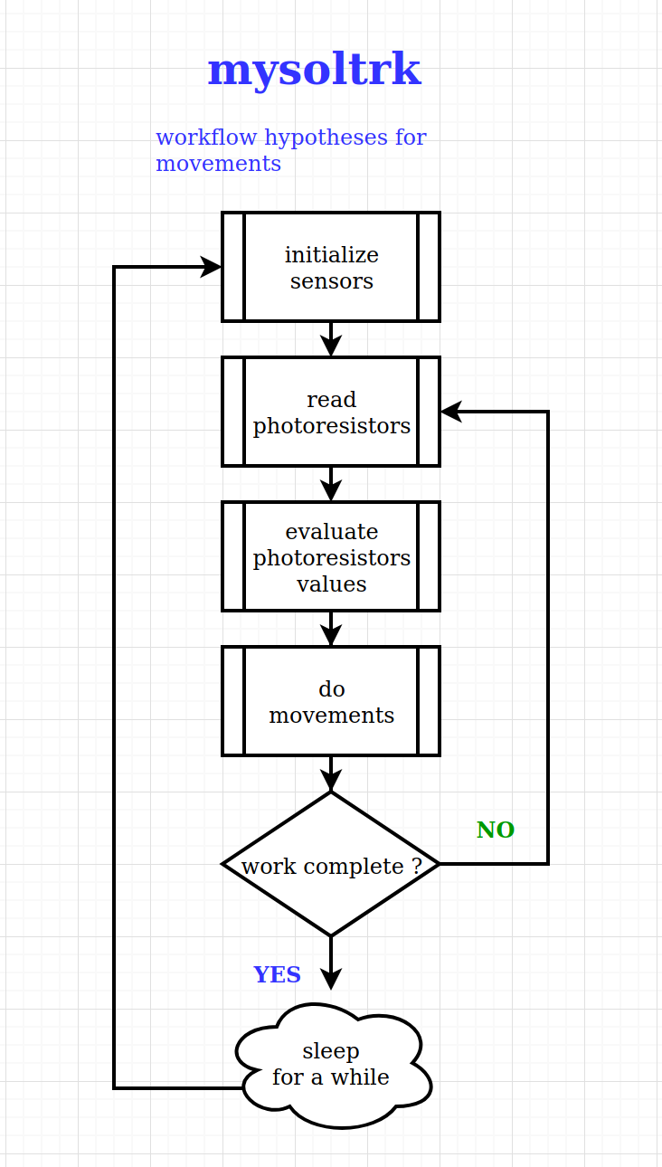
Let's look at some snippet of code:void loop() { unsigned long startedAt = millis(); workIsCompleted = false; readPhotoresistorValuesAndEvaluateMovements(); Serial.println("Tracker start"); while (!workIsCompleted && !isLowVREF()) { movePanel(); if (millis() - startedAt > MAX_MILLISECONDS_WORK) { Serial.println("Exceeded work time limit"); workIsCompleted = true; } else { readPhotoresistorValuesAndEvaluateMovements(); } delay(10); } Serial.println("Tracker complete"); processMosfet(); sleepForMilliseconds(SLEEP_DELAY); }The loop() code follow the flow chart that we had shown in the previous log.
Summing up:
- read photoresistors values and calculate movements
- move panel
- read photoresistors values (again) and calculate next movements
- if there are no moves or time is up, go to sleep; otherwise return to step 2
- after completing the movements, evaluate whether to turn on the mosfet based on the amount of light read
- sleep for a set amount of time
- repeat from step 1
Quite simple isn't it? Well, the hard work is to create a right combination between the reading of the photoresistors, the reading of the pin shunt and of VREF. And a lot of trying..
But how are the movements performed? Here is an example:
    if (moveUp)
    {
        Serial.println("move UP ^^");
        eos_br = false;
        if (!move(ACTUATOR_R_PIN1, MAX_MILLISECONDS_MOVEMENT, MAX_SHUNT_VALUE_R))
        {
            eos_tr = true;
        }
        eos_bl = false;
        if (!move(ACTUATOR_L_PIN1, MAX_MILLISECONDS_MOVEMENT, MAX_SHUNT_VALUE_L))
        {
            eos_tl = true;
        }
    }
To implement the upward movement, the two actuators are switched on one at a time. This way you get the desired result without consuming too much.Variable "eos_tr" (Top Right), "eos_tl" (Top Left) are used to mark the limit switches. This is useful for movements calculation.
However, the code has been written for maximum readability and understanding.
Let's watch together the video made with a DYI esp32cam powered directly by the mysoltrk prototype:
Sorry for the low quality video. esp32cam provides low resolution images with little detail.
However we think it is enough to show how it works
Project completed ? That's all ? Well.. no!
Thanks to the award received, we now have the opportunity to extend the challenges we set ourselves at the beginning.
Our plans include the purchase of material useful for the construction of further prototypesWe want to explore these further aspects:
- What size of panels can we move with our actuators ?
- Is there a possibility to use the same technique to move large panels?
They seem like demanding challenges to us, but given the results we have achieved, we are quite optimistic !
-
Software design: work in progress
08/05/2023 at 15:19 • 0 commentsHi everyone!
We are quite busy developing solar tracking software.
The algorithm is almost defined, we are studying some behaviors in the field (directly in the sun)
Here is a preview of the flowchart, the "loop" function on Arduino code:
![]()
Prototype in action:
![]()
Stay tuned..
-
Let's go outside to find the sun - first test
07/03/2023 at 18:41 • 0 commentsAfter completing the assembly, we had to wait for a sunny day.
Here is the result of the test with prototype #2 using the code showed on this log:
At this point we can consider the hardware is working as expected and we can concentrate on the software implementation of the solar tracker.
Stay tuned!
-
Ready to go outside: the assembling
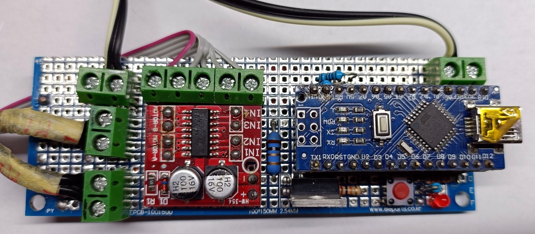
06/26/2023 at 13:02 • 0 commentsThese days we have focused on transforming the breadboard circuit into a solderable breadboard circuit, adding a small box to enclose everything.
Here is the result of prototype #2:
![]()
![]()
As you can see, all components used on prototype #1 are in prototype #2. We have added a little led for debug (bottom right) connected to the mosfet pin.
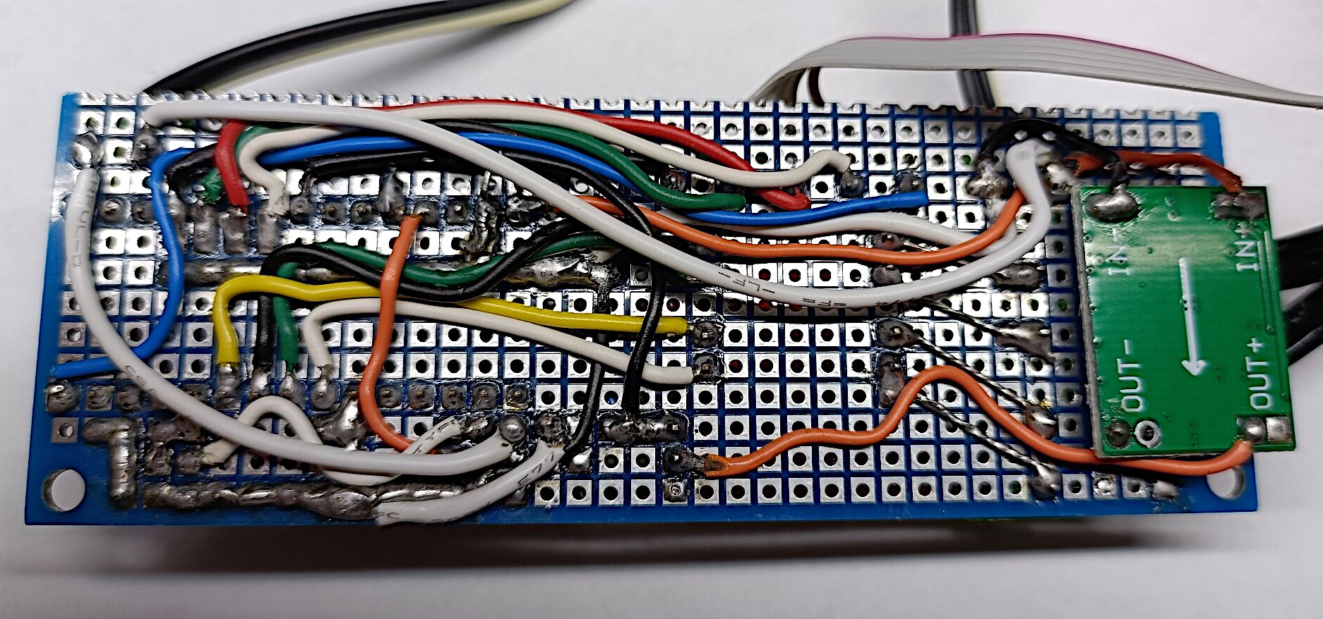
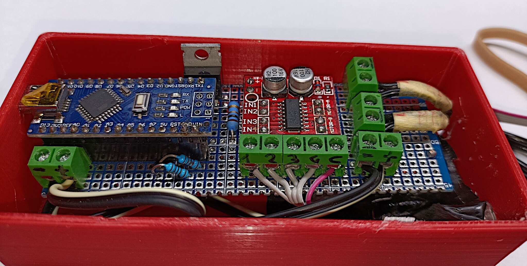
The circuit inside the box:
![]()
We have added two usb connector for USB IN and USB OUT, fixing with hot glue:
![]()
![]()
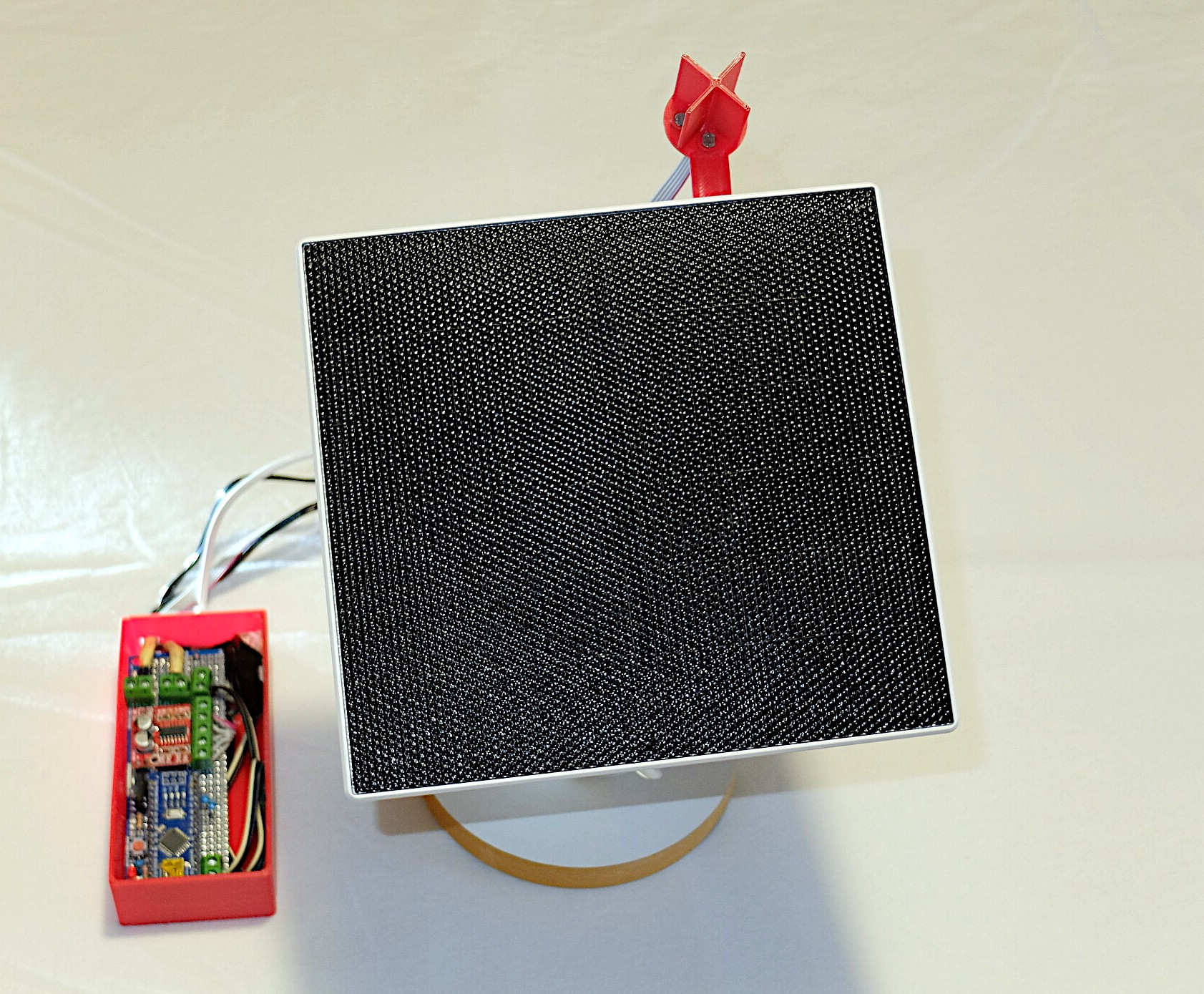
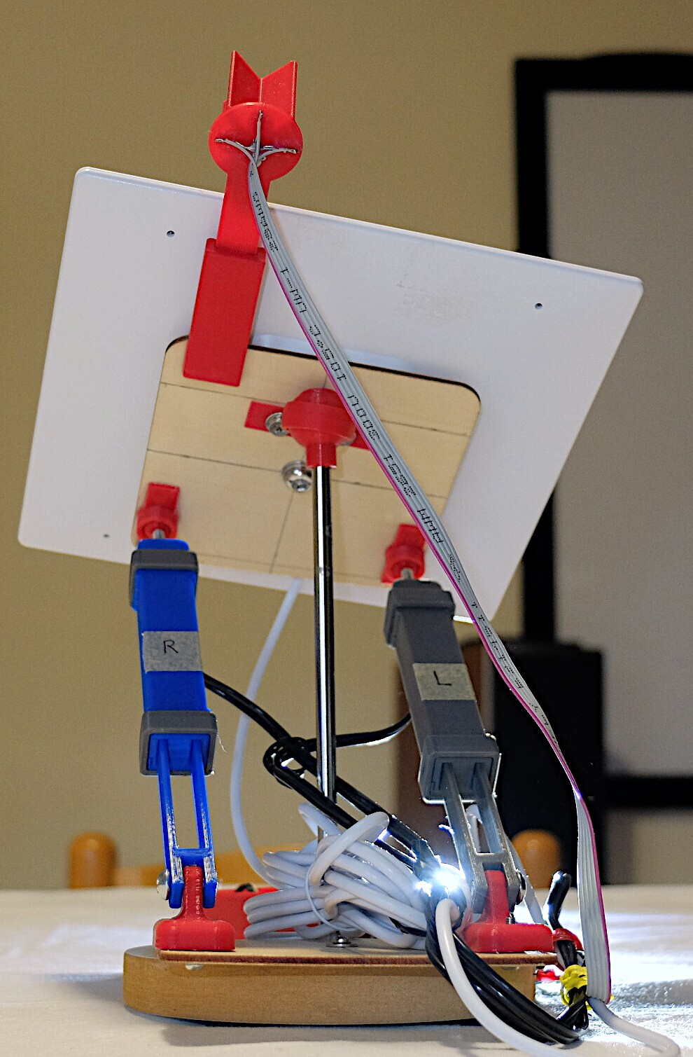
By connecting the circuit to the actuators, to the photoresistors and to the solar panel we obtain this beautiful result to see:
![]()
![]()
Now we are ready to do some tests outside.
-
Software design: transform an idea into real movements
06/16/2023 at 07:55 • 0 commentsNow it's time to test the prototype #1 with the actuators.
We have realized a Arduino example, you can find it at github
Before we talk, let's watch the video:
The first think we said was: it works!
With a tiny processor, with a bunch of discrete components we are able to pilot a DIY actuators without limit switches.
This trick helps us to significantly reduce the complexity of the hardware.
Some notes about the code
// Program params #define MAX_SAMPLES 10 #define IGNORE_SHUNT_VREF_FOR_ 1000L // milliseconds #define MAX_SHUNT_VALUE 20 // threshold #define MIN_VREF_VALUE 100 // below this value the external power supply (eg: solar panel) supplies too little energy #define MAX_SECONDS_MOVEMENT 180 // max seconds to move actuator- MAX_SAMPLES: we use an array to read analog values and give an average of the values derived from the scan
- IGNORE_SHUNT_VREF_FOR_: when motor starts, we can ignore first values
- MAX_SHUNT_VALUE: a reference value, above this value it is assumed that the motor is straining and therefore it can be deduced that it has reached the end of its stroke
- MIN_VREF_VALUE: a reference values, below this value it is assumed that external power (solar panel) produce few energy and the engine should be stopped
- MAX_SECONDS_MOVEMENT: an arbitrary value, high enough to reach the end of actuator stroke
    digitalWrite(ACTUATOR_R_PIN1, LOW);
    digitalWrite(ACTUATOR_R_PIN2, LOW);
    digitalWrite(ACTUATOR_L_PIN1, LOW);
    digitalWrite(ACTUATOR_L_PIN2, LOW);
When program start, we put L298n pins to low.
Next, we put pin to high once at time to keep consumption low.
The result is one move at time for a single actuator.
Current absorption
As you can see on video, the circuit consumes about 0.1W with motor off and 0.2W with one motor on.
We think a good milestone has been reached!
mysoltrk - a solar tracker, reinvented
A different approach for a solar tracker, alternative movements, to be installed on the outside, to optimize the efficiency of solar panels