 Fulvio
-
1Buy supplies
In "Files" section you can download a pdf file whith a bill of materials.
Consider that you may already have some of the material listed in your garage, such as screws and plywood. -
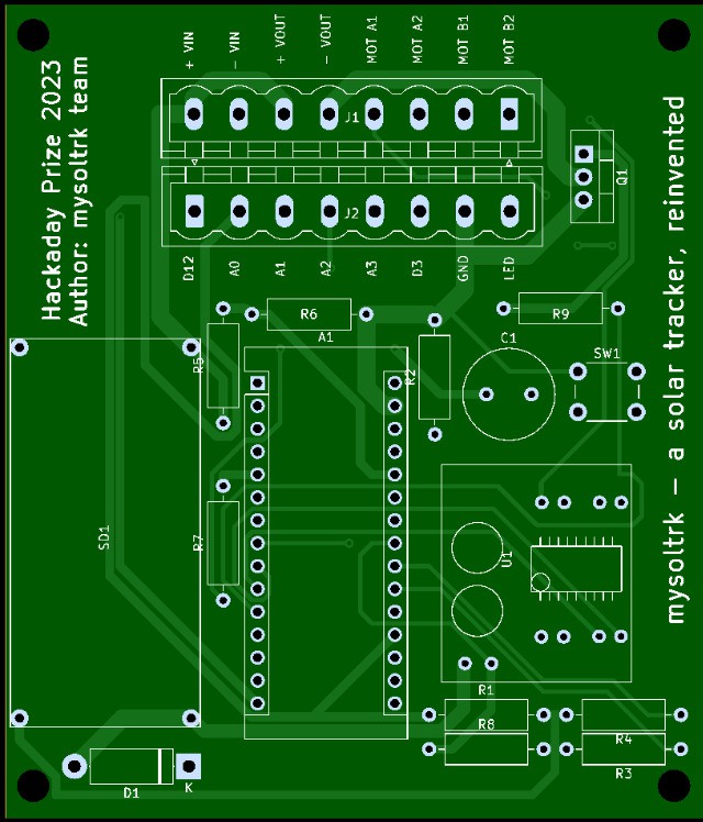
2Buy PCB
Download "Mysoltrk Gerber.zip" and put an order on your favorite pcb manufacturer
![]()
-
3Buy Solar panel
Buy a solar panel from you favorite online store.
You can choose from a myriad of panels, choose one not too big e not too heavy.
The dimension of panel for the first prototype of mysoltrk is about 17x17cm, a solar panel for ip camera. -
43D Print
With you 3D printer, print two "mysoltrk-actuator.stl", one "mysoltrk-joints.stl" and one "mysoltrk-viewfinder.stl"
Quality is not important, you can also print at 0.28.
Print with PETG because PLA material does not resist rain and sun. -
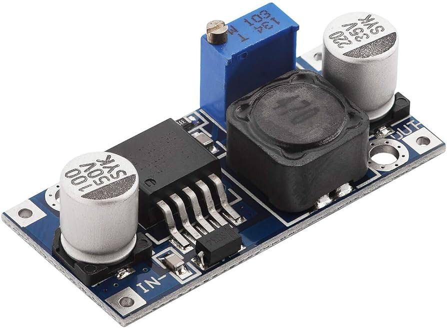
5Step down setup
Using an external power supply, tweak the output value to 5-5.2V.
The input voltage must be equal to the maximum value of your solar panel.
This step must be done before PCB assembly!![]()
-
6Assemble the PCB
Solder all parts like this photo:
Pay attention to the position of the resistors, diode and transistor
For Arduino Nano, we recommend you use tulip connector.![]()
-
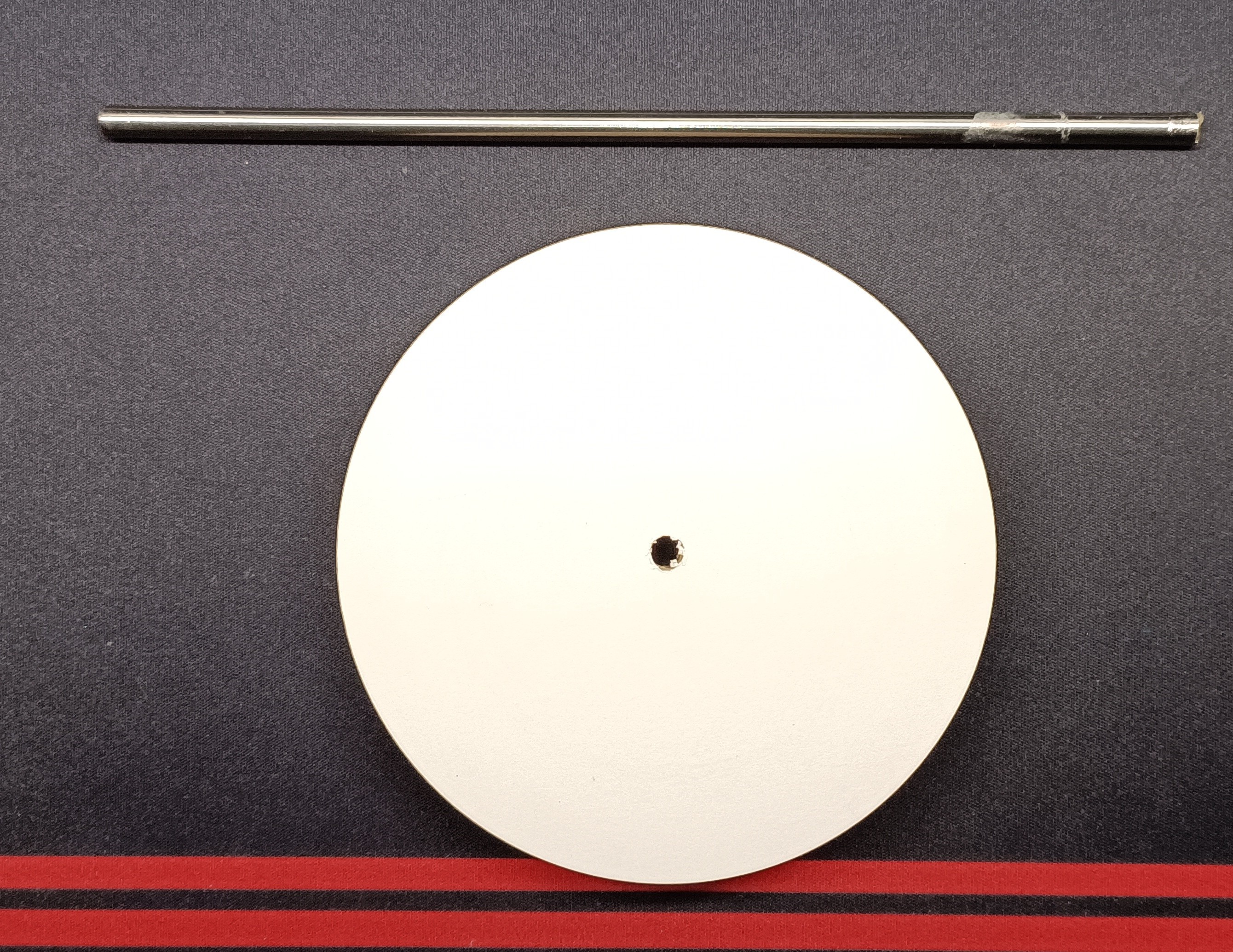
7Bonding the main support
For this step, we invite you to use your DIY skills!
Using a 6mm tube and a plywood, build a solid structure that can hold your solar panel.
Connect the solar panel to vertical tube via the ball joint.
You can use a piece of plywood cut to the size of your solar panel to help you connect the ball mount with the vertical tube.
The position of the ball joint should be as central as possible.![]()
-
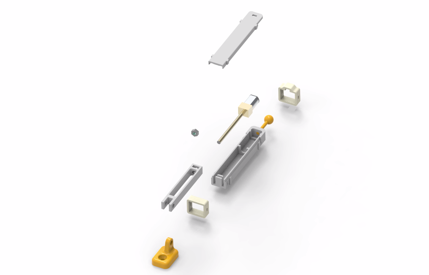
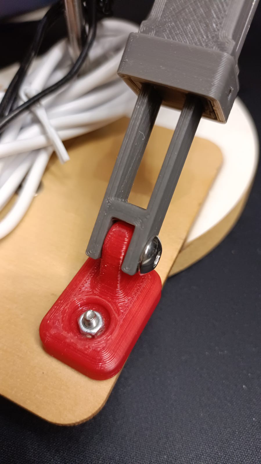
8Assemble the actuators
For assembly two actuators together with N20 gear motors:
![]()
Before to assemble, solder a two pin electrical cable to the motor (eg: black&red 22AWG)
Use an external power supply set to 5V test the wiring and movements.
Put one actuator to minimum position, the second one to maximum position: in this way the positioning of the actuators will be easier.The video of the assembly:
-
9Assemble the viewfinder
Put four photoresistor inside holes of 3D printed viewfinder.
Take the terminals closest to the center and connect them together.
Solder a cable with 5 connectors long enough to allow you to easily position the circuit.![]()
-
10Assemble the actuators to main support
Another DIY step!
Place the actuators behind the solar panel and look for the best position that allows the panel to move both east and west, but also up and down.
Once you have found the best position for your panel, secure the joints with screws or glue.![]()
![]()
mysoltrk - a solar tracker, reinvented
A different approach for a solar tracker, alternative movements, to be installed on the outside, to optimize the efficiency of solar panels


Discussions
Become a Hackaday.io Member
Create an account to leave a comment. Already have an account? Log In.