Close
0%
0%

Repurposed wifi controller as GPS-based NTP server

An old Meru MC1500 wifi controller retrofitted with Debian and a GPS receiver becomes an accurate private NTP server

Similar projects worth following
Of course, this kind of project is nothing new. GPS-based NTP servers have been around for some time (pun intended!), and many projects are based on RPis. But because of chip shortage and RPis becoming as cheap as a used car could be, retrofitting some old unused hardware may be a good way of saving a few bucks while having fun modding hardware!

The victim is going to be an old Meru MC1500 wifi controller I bought a few months ago as "for parts" on eBay.

GPS module will be a cheap Neo 6M module from Amazon with an external antenna. It might be upgraded later.

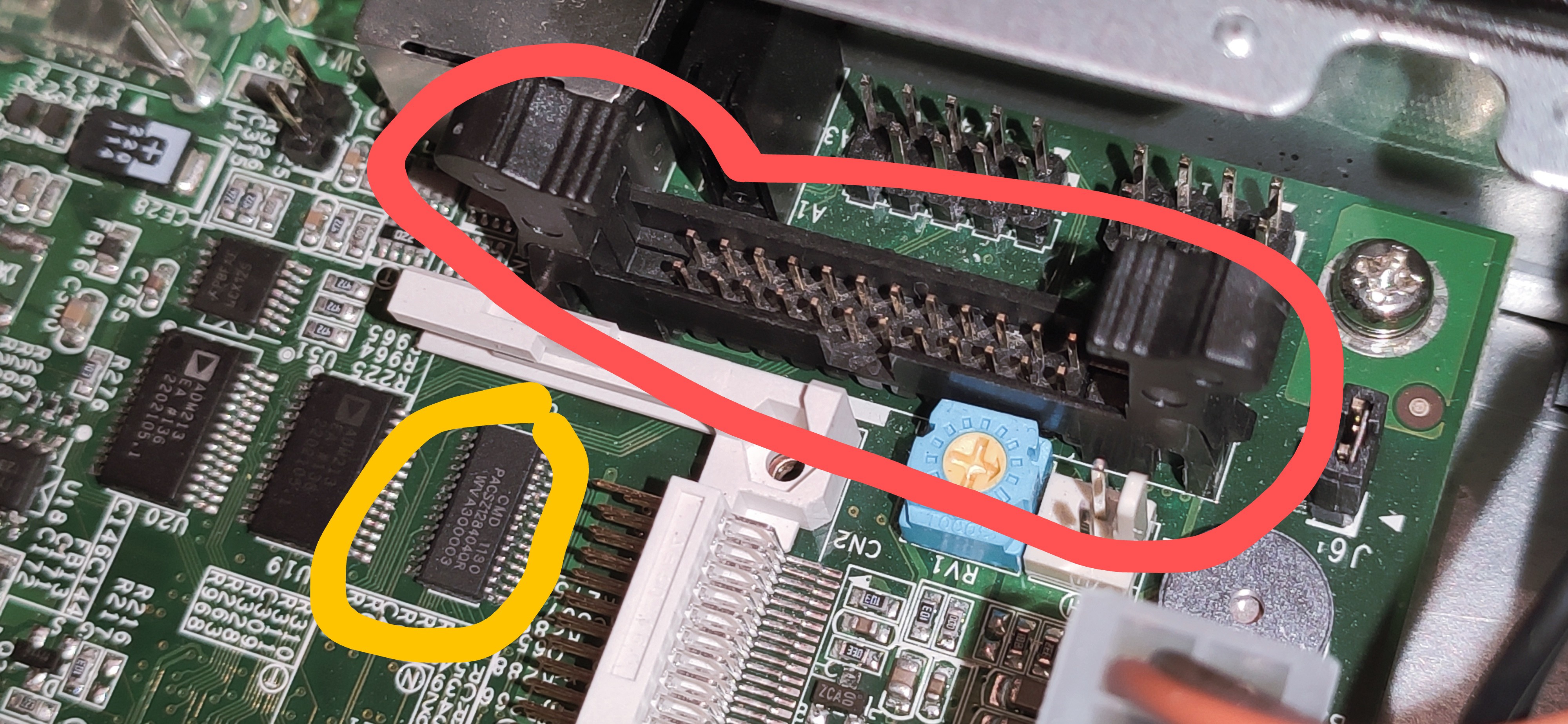
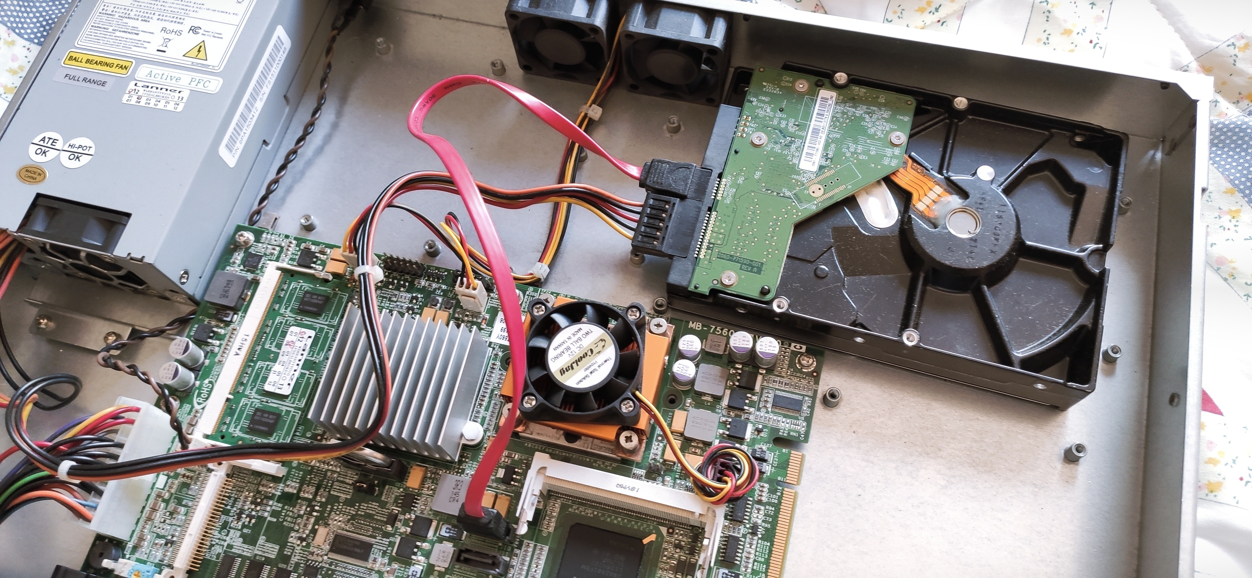
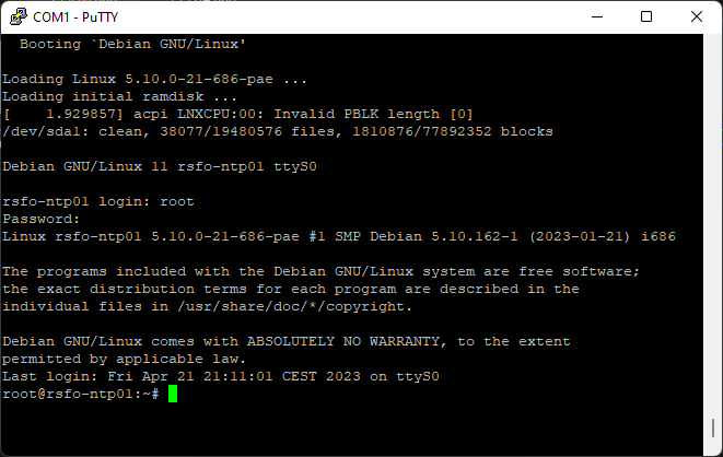
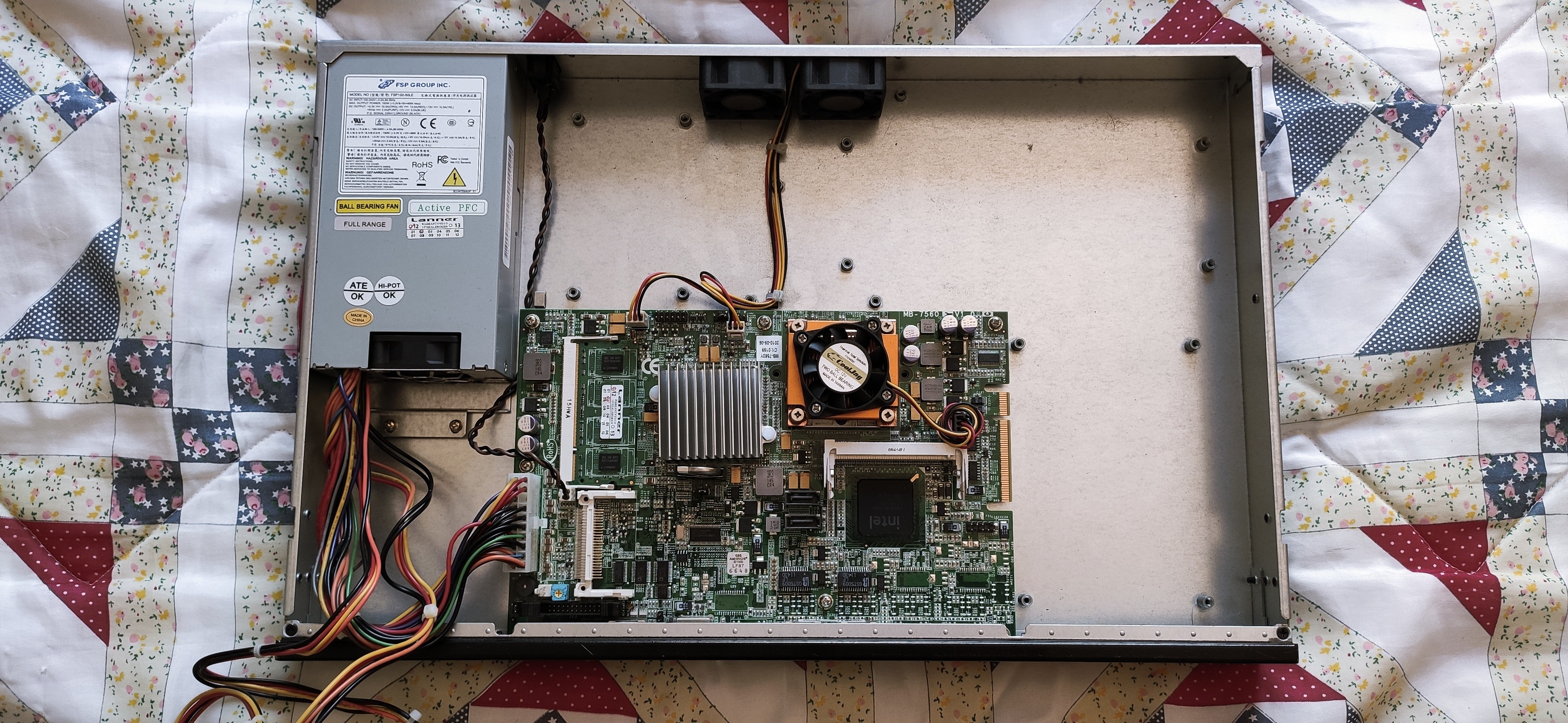
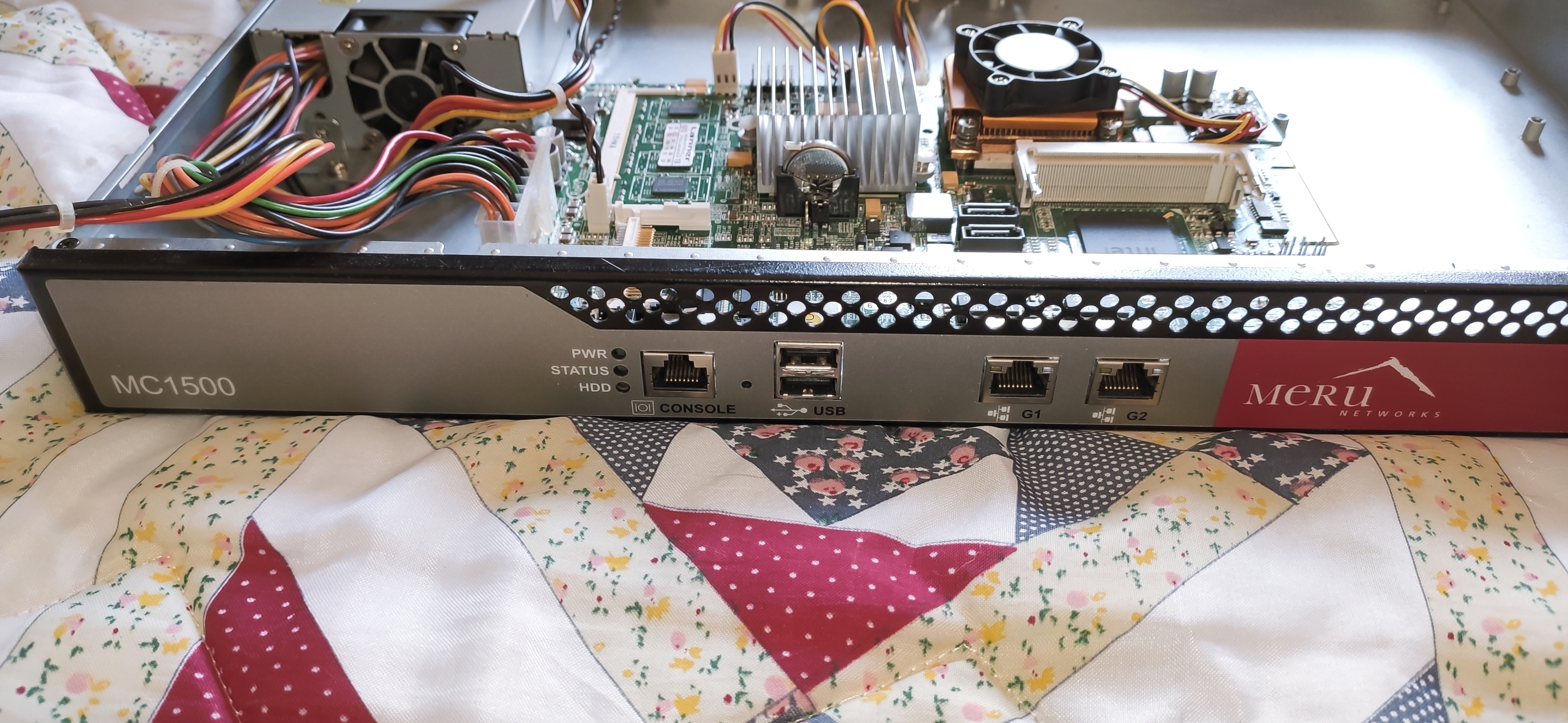
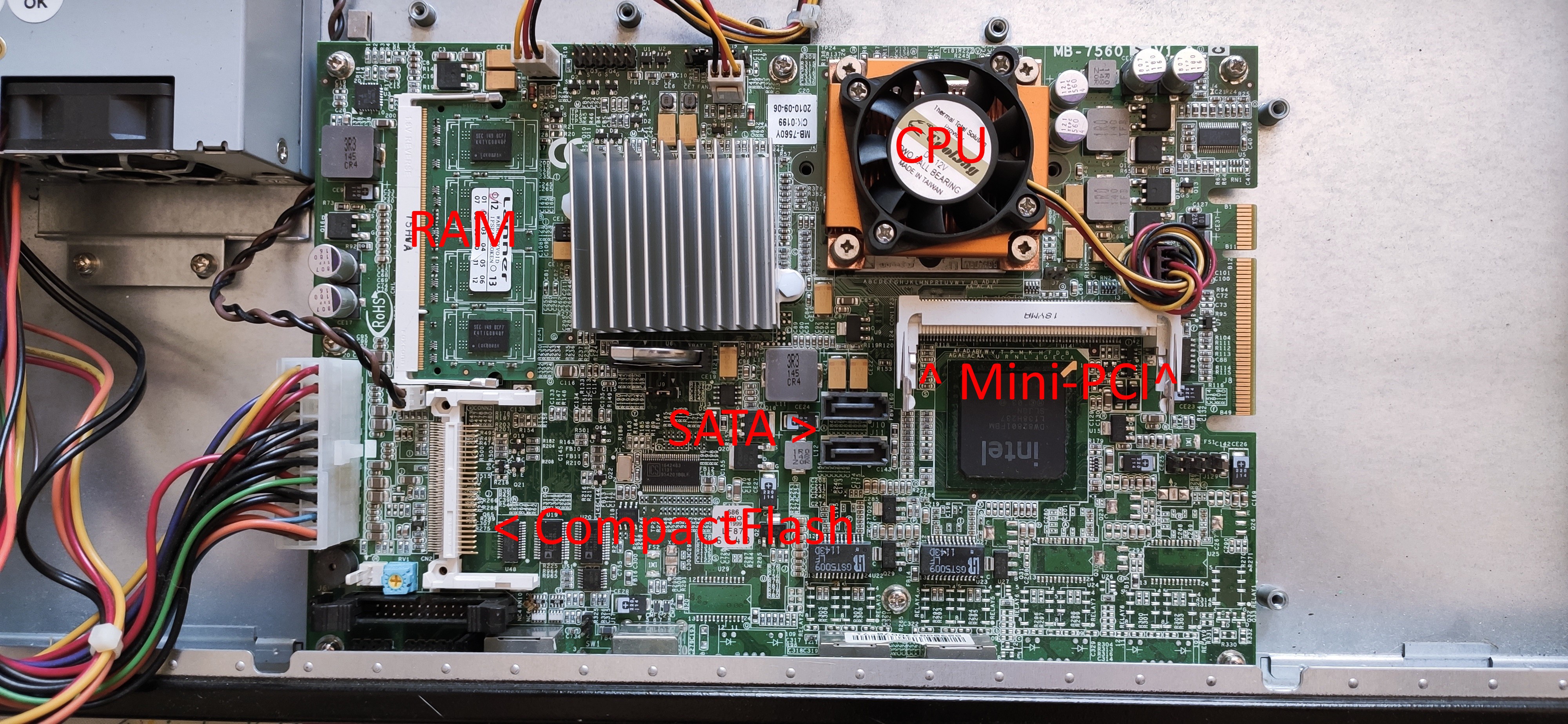
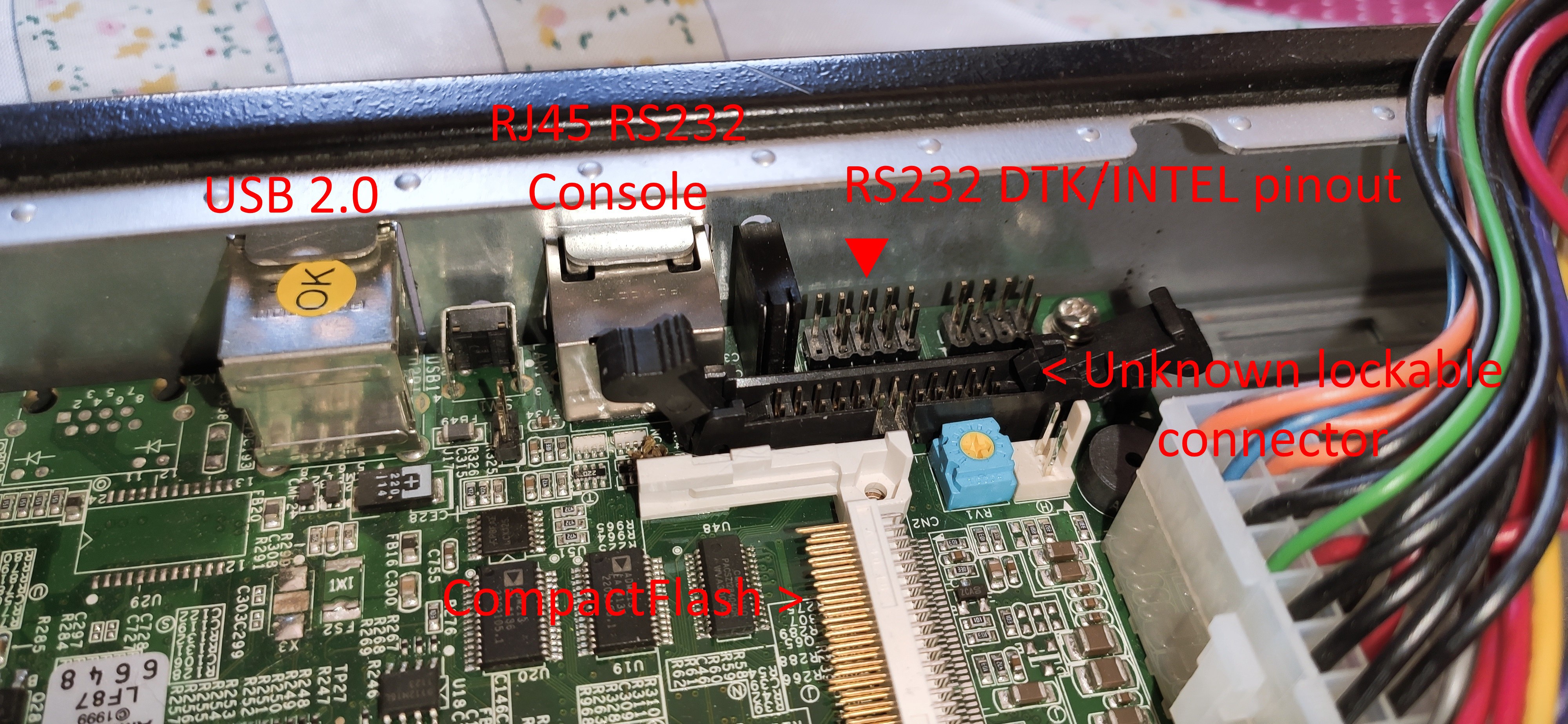
I bought this Meru MC1500 controller on eBay for cheap, it was listed as broken. I carefully opened the case before powering it up for the first time, to make sure the hardware was in good shape. I was more than happy to see it booting, and loading Grub! However, the firmware would not load properly because of the corrupted 4GB CompactFlash memory card. This CF memory is used to store the controller firmware which is based on Linux/Unix. I was able to salvage the license file from the card, just in case. 

This project's end goal is to have an accurate NTP server using GPS time as a reference for offline use, and using the GPS PPS (pulse per second) output to discipline the clock down to the GPS specifications. 

Ultimately, I would like to add an OCXO and output a 10 MHz for precise time reference... We will see that later!

Trimble 97975-00.pdf

Trimble starter kit user guide based on the 97975/96975 chip, this chip includes its own 10 MHz TTL CMOS output.

Adobe Portable Document Format - 3.10 MB - 05/08/2023 at 14:23

Preview
Download

Trimble 66266-00.pdf

Trimble starter kit user guide based on the 66266 chip.

Adobe Portable Document Format - 2.20 MB - 05/08/2023 at 14:16

Preview
Download

  • 1 × Meru MC1500 Wifi Controller
  • 1 × SATA hard drive or SSD, or CompactFlash
  • 1 × NEO-6M GPS Module with PPS output + antenna
  • 1 × RS232-TTL converter (MAX3232 module, can be made DIY)

  • Experimenting with a weird GPS receiver

    Remi Serriere05/08/2023 at 14:26 0 comments

    Not all GPS receivers are alike!

    The GPS receiver I first ordered on Amazon is not designed to be used as an accurate time source. Don't get me wrong, the U-Blox NEO-6M is a good receiver but it was designed as a general-purpose GPS receiver. It processes and outputs the location every second, that's a waste of resources and a potential source of time drift. On top of that, the device would not accept a lot of commands from the U-Blox Center software which lead me to suspect I have a cheap Chinese clone... Oh well...

    Many dedicated GPS time sources can be found on eBay, mostly reclaimed from "starter kits" or cellular towers. If you know what you are looking for, gems can be found for cheap. Some units are even equipped with TCXO, OCXO, or DCXO if you are lucky. More on that later maybe :)

    There is one important thing to keep in mind with this kind of device: they require a stationary antenna! They are designed to stay in the same place, not to be moved around. A time-dedicated GPS receiver should stop reporting its position after a specific, sometimes configurable, amount of time. During this first phase of operation, the chip would average its position and then save it in its memory. After that, the chip would only report the time of day, some internal status for monitoring purposes, and PPS. 

    Trimble 66266

    The first time-oriented GPS receiver I ordered was a Trimble board based on a Trimble 66266, for less than $15 on eBay probably reclaimed from a Trimble starter kit. 

    Trimble 66266 close view
    Trimble 66266 close view

    It has an SMB antenna connector and a 3.3v to 5v active antenna is needed. These receivers are quite accurate, down to 15 ns according to the datasheet.

    Fortunately, the kit's user guide is still available and has all the information we need including the board's pinout (the connector is a 2.00 mm pitch 2x4 pins, not a standard 2.54 mm):

    Pin numberFunctionDescription
    1Antenna power input3.0 V DC to 5.5 V DC, 55 mA max
    2Prime power input3.3 V DC ±0.3 V DC
    3TXD APort A transmit, CMOS
    4ReservedReserved
    5RXD APort A receive, CMOS
    61 PPSOne Pulse-Per-Second, CMOS
    7No connectNot used
    8GNDGround, Power and Signal

    The user guide can be downloaded from here or from this project's main page.

    By default, the chip should have the following configuration:

    SettingValueDescription
    Serial port9600/8/Odd/1/NoneBaud rate/Data bits/Parity/Stop bits/Flow control
    ProtocolTSIPProprietary binary "Trimble Standard Interface Protocol" by default
    NMEA disabled, can be activated but not needed
    PPSAlways on, rising edgeAlways on, with or without a GPS signal
    Can be set to "only when 1 or 3 satellites are in use"
    Self-SurveyEnabled, autosave, 2000Self-survey enabled by default
    The position is saved to flash on self-survey completion
    2000 fixes are required until self-survey completion

    After ordering an SMB to SMA cable adapter and a second active GPS antenna, it was time to hook this new toy to a computer. The Meru NTP server is in semi-production right now, so it will not be used... For now! I will not talk about the wiring much here because everything is temporary and not related to the Meru server.

    Lady Heather to the rescue for the first power-up

    Lady Heather is a great piece of art! But a rather complicated software. Since the GPS receiver is also complicated to talk to, with a proprietary protocol, I figured this software could be of good use. Indeed it was! However:

    • While you can build and run it on Linux, the installer is made for Windows.
    • It needs a serial port with DCD support, even if you don't care about PPS for now.
    • Most USB to Serial interfaces don't support DCD, I used the same RS232-TTL board as before on my Windows workstation for that reason, connected to the DB9 RS232 port on the motherboard.

    Version 5.0 can be downloaded from here and can be upgraded to version 6.14 Beta

    If the GPS is connected to COM1, simply execute the shortcut on the desktop. Lady Heather will try to autodetect and...

    Read more »

  • Making some noise

    Remi Serriere04/23/2023 at 17:54 0 comments

    So we now have a working NTP server, but how can we, humans, know what time it is? What about audible feedback?

    There is no soundcard in the Meru of course, but there is a basic buzzer that we can use. So let's install the "beep" package first:

    apt install beep

    And let's create a bash script, let's say "/root/ring.sh", 

    #! /bin/bash
    
    # Getting the number of hours (12 hours format)
    HOUR=$(date +"%-I")
    
    # Getting attention "hey listen, I'm gonna tell you what time it is!"
    beep -f 440 -l 100
    sleep 0.050
    beep -f 880 -l 100
    sleep 0.050
    beep -f 440 -l 100
    sleep 0.050
    
    # Wait a bit
    sleep 1
    
    # Ring HOUR times
    for (( i=0; i<$HOUR; i++ ))
    do
            # This can be modified
            MAX=35 
    
            # Looping
            for (( j=0; j<$MAX; j++ ))
            do
                    beep -f 440 -l $((MAX - i))
                    sleep $((j / 1000))
            done
            
            # Waiting for 1 second
            sleep 1
    done
    

    Now edit the "root" crontab: 

    # Execute as root
    crontab -e

    And finally, insert the following cron line to execute the script every ticking hour:

    0 * * * * bash /root/ring.sh

    Now wait for an hour to tick, and listen :)

  • Configuring the software

    Remi Serriere04/23/2023 at 17:44 0 comments

    Awesome! We have wired a GPS with its PPS to the motherboard, and now what?

    First, we need a few missing components: "gpsd" will handle the GPS, while "chrony" will take care of the NTP.

    # Installing required packages
    apt install gpsd gpsd-clients pps-tools chrony
    
    # Making sure PPS kernel module is loaded
    modprobe pps_ldisc
    
    # Attaching PPS device on serial port
    ldattach PPS /dev/ttyS1
    
    # Allow Chrony sockets in AppArmor
    apt install apparmor-utils
    aa-complain /usr/sbin/chronyd
    

    By now, the PPS LED on the GPS module is ticking meaning we should have a GPS fix. Let's test the PPS output to see if it is working. It is indeed ticking as expected:

    root@rsfo-ntp01:~# ppstest /dev/pps0
    trying PPS source "/dev/pps0"
    found PPS source "/dev/pps0"
    ok, found 1 source(s), now start fetching data...
    source 0 - assert 1682168016.866888991, sequence: 2171 - clear  1682168015.966901011, sequence: 2952
    source 0 - assert 1682168016.866888991, sequence: 2171 - clear  1682168016.966901919, sequence: 2953
    source 0 - assert 1682168017.866881448, sequence: 2172 - clear  1682168016.966901919, sequence: 2953
    source 0 - assert 1682168017.866881448, sequence: 2172 - clear  1682168017.966892630, sequence: 2954
    source 0 - assert 1682168018.866880401, sequence: 2173 - clear  1682168017.966892630, sequence: 2954
    source 0 - assert 1682168018.866880401, sequence: 2173 - clear  1682168018.966878452, sequence: 2955
    source 0 - assert 1682168019.866878585, sequence: 2174 - clear  1682168018.966878452, sequence: 2955
    source 0 - assert 1682168019.866878585, sequence: 2174 - clear  1682168019.966890814, sequence: 2956
    source 0 - assert 1682168020.866877816, sequence: 2175 - clear  1682168019.966890814, sequence: 2956
    source 0 - assert 1682168020.866877816, sequence: 2175 - clear  1682168020.966887531, sequence: 2957

    Now, let's configure the GPSD daemon. This daemon will talk to the GPS module while allowing multiple processes to access the GPS information. This would not be possible if we were using the serial port directly from the NTP server. Edit the file "/etc/default/gpsd":

    # GPS is conected to ttyS1, the 2nd hardare serial port
    DEVICES="/dev/ttyS1"
    
    # Options we want to pass to gpsd
    # -s 9600 = baudrate, -G = listen to any address, -n = don't wait for clients to poll GPS
    GPSD_OPTIONS="-s 9600 -G -n"
    
    # We don't care about USB modules, let's ignore them!
    USBAUTO="false"

    We also need to configure the Chrony daemon by editing the file "/etc/chrony/chrony.conf". The "makestep" should not be required, but since the Meru has a bad RTC/BIOS battery the time would keep reverting to 2002... Chrony doesn't like that and doesn't update the time with such an offset in timing. With this command, Chrony will force updates on the first 10 syncs. 

    # Allow connections from remote
    allow
    
    # Reference clocks, PPS locked on GPS
    refclock SOCK /run/chrony.ttyS1.sock refid GPS precision 1e-1
    refclock PPS /dev/pps0 lock GPS refid PPS precision 1e-9 poll 2
    
    # Step the clock on first 10 updates if ofset is larger than one second
    makestep 1 10

    I had trouble starting Chrony on boot because the PPS device (/dev/pps0) would not be initialized yet. So I added an "ExecStartPre" command in Chrony's daemon service file located at "/lib/systemd/system/chrony.service":

    [Unit]
    Description=chrony, an NTP client/server
    Documentation=man:chronyd(8) man:chronyc(1) man:chrony.conf(5)
    Conflicts=openntpd.service ntp.service ntpsec.service
    Wants=time-sync.target
    Before=time-sync.target
    After=network.target
    ConditionCapability=CAP_SYS_TIME
    
    [Service]
    Type=forking
    PIDFile=/run/chrony/chronyd.pid
    EnvironmentFile=-/etc/default/chrony
    ExecStartPre=bash -c '/usr/sbin/ldattach PPS /dev/ttyS1 && /bin/sleep 10'
    ExecStart=/usr/sbin/chronyd $DAEMON_OPTS
    PrivateTmp=yes
    ProtectHome=yes
    ProtectSystem=full
    ProtectControlGroups=yes
    ProtectKernelModules=yes
    ProtectKernelTunables=yes
    
    [Install]
    Alias=chronyd.service
    WantedBy=multi-user.target
    

    Make sure the GPSD service is set to start after ...

    Read more »

  • Interfacing a GPS

    Remi Serriere04/21/2023 at 22:45 0 comments

    Of course, Debian cannot get GPS messages from the sky without a GPS module. Since we want to discipline the NTP/kernel accurately, we need a GPS module with a PPS (pulse per second) output. USB modules should be avoided because of delays that can be caused by the TTL-USB chip, and most of them can't handle PPS anyways.

    I decided to buy a module from Amazon, it has a PPS output and a TTL interface making it more reliable than USB. The GPS chip is a NEO-6M which will do the trick for now. A proper chip for time reference should be the NEO-6T but more on that latter.

    NEO-6M GPS module on Amazon
    NEO-6M GPS module on Amazon

    On an RPi the PPS output could be wired to a GPIO, but since we have a "real" motherboard we have 2 options:

    1. Parallel port: PPS output is wired to the ACK pin of the port, but we either need a serial port or serial-to-USB to get the actual GPS time from the NMEA messages.
    2. Serial port: PPS output is wired to the DCD pin of the port, TX and RX can be used to get the actual GPS time messages from NMEA. 

    Option 2 is great, and since there is a second serial port on the motherboard we can use it! But there is a catch: the port itself expects RS232 signals, and they are incompatible with the module TTL output. A simple MAX3232 with a few capacitors can be used as an interface between the two, and I went with a pre-made module from Amazon, again. 

    MAX3232 RS232-TTL interface module on Amazon
    MAX3232 RS232-TTL interface module on Amazon

    Here are some pictures of the wiring:

    MAX3232 module soldered on header pins
    MAX3232 module soldered on header pins. This module actually uses the two sides of the PCB, each side corresponds to one channel on the MAX3232 chip. It can be interfaced with two serial ports, one on each side of the PCB. Neat! 
    Full view of circuit board
    Circuit board with MAX3232 module on headers (removable), the power coming from the 2nd SATA power cable, a jumper allowing me to switch power to the GPS from 5v to 3.3v. Vcc and Gnd are inverted between the MAX3232 and GPS. An old "CD-ROM audio" cable was used from the board to the serial port, the shielding is connected grounded at the port and here at the board. The PPS LED on the GPS module was replaced by a header but that's optional. 
    Serial port wiring
    Wiring at the serial port. Pins 2/4/6/7/8 are not used. Pins used are: 1 = PPS, 3 = RX, 5 = TX, 9 = GND. Full pinout available on this website, second diagram. 
    PPS LED on the front
    The PPS LED moved to the front where it can be seen. 
    Side view of the PCB
    Side view of the PCB. The hard drive is now bolted to a plexiglass plate, itself bolted to the frame. The GPS antenna is extended to the back.
    Top view
    Top view, the GPS antenna extension is clearly visible. A 6.5 mm drill bit was used to drill a hole for the SMA connector.
    Full view
    Full top view of the Meru NTP Server! The antenna is in the case for the picture only, it will be installed outdoors when the project is complete. There is still plenty of room for future upgrades :)

  • More details about the hardware

    Remi Serriere04/21/2023 at 20:03 0 comments

    First, it looks like this connector there is a parallel port. It is connected to a PACSZ1284 chip so there might be something to do with this later!

    And a few information about the hardware from the OS:

    lspci

    root@rsfo-ntp01:~# lspci
    00:00.0 Host bridge: Intel Corporation Mobile 915GM/PM/GMS/910GML Express Processor to DRAM Controller (rev 04)
    00:02.0 VGA compatible controller: Intel Corporation Mobile 915GM/GMS/910GML Express Graphics Controller (rev 04)
    00:02.1 Display controller: Intel Corporation Mobile 915GM/GMS/910GML Express Graphics Controller (rev 04)
    00:1c.0 PCI bridge: Intel Corporation 82801FB/FBM/FR/FW/FRW (ICH6 Family) PCI Express Port 1 (rev 04)
    00:1c.1 PCI bridge: Intel Corporation 82801FB/FBM/FR/FW/FRW (ICH6 Family) PCI Express Port 2 (rev 04)
    00:1d.0 USB controller: Intel Corporation 82801FB/FBM/FR/FW/FRW (ICH6 Family) USB UHCI #1 (rev 04)
    00:1d.1 USB controller: Intel Corporation 82801FB/FBM/FR/FW/FRW (ICH6 Family) USB UHCI #2 (rev 04)
    00:1d.7 USB controller: Intel Corporation 82801FB/FBM/FR/FW/FRW (ICH6 Family) USB2 EHCI Controller (rev 04)
    00:1e.0 PCI bridge: Intel Corporation 82801 Mobile PCI Bridge (rev d4)
    00:1f.0 ISA bridge: Intel Corporation 82801FBM (ICH6M) LPC Interface Bridge (rev 04)
    00:1f.2 IDE interface: Intel Corporation 82801FBM (ICH6M) SATA Controller (rev 04)
    00:1f.3 SMBus: Intel Corporation 82801FB/FBM/FR/FW/FRW (ICH6 Family) SMBus Controller (rev 04)
    02:00.0 Ethernet controller: Intel Corporation 82574L Gigabit Network Connection
    03:00.0 Ethernet controller: Intel Corporation 82574L Gigabit Network Connection

    lscpu

    root@rsfo-ntp01:~# lscpu
    Architecture:                    i686
    CPU op-mode(s):                  32-bit
    Byte Order:                      Little Endian
    Address sizes:                   32 bits physical, 32 bits virtual
    CPU(s):                          1
    On-line CPU(s) list:             0
    Thread(s) per core:              1
    Core(s) per socket:              1
    Socket(s):                       1
    Vendor ID:                       GenuineIntel
    CPU family:                      6
    Model:                           13
    Model name:                      Intel(R) Celeron(R) M processor         1.50GHz
    Stepping:                        8
    CPU MHz:                         1500.033
    BogoMIPS:                        3000.06
    Vulnerability Itlb multihit:     KVM: Mitigation: VMX unsupported
    Vulnerability L1tf:              Mitigation; PTE Inversion
    Vulnerability Mds:               Vulnerable: Clear CPU buffers attempted, no mic
                                     rocode; SMT disabled
    Vulnerability Meltdown:          Mitigation; PTI
    Vulnerability Mmio stale data:   Unknown: No mitigations
    Vulnerability Retbleed:          Not affected
    Vulnerability Spec store bypass: Vulnerable
    Vulnerability Spectre v1:        Mitigation; usercopy/swapgs barriers and __user
                                      pointer sanitization
    Vulnerability Spectre v2:        Mitigation; Retpolines, STIBP disabled, RSB fil
                                     ling, PBRSB-eIBRS Not affected
    Vulnerability Srbds:             Not affected
    Vulnerability Tsx async abort:   Not affected
    Flags:                           fpu vme de pse tsc msr pae mce cx8 apic sep mtr
                                     r pge mca cmov clflush dts acpi mmx fxsr sse ss
                                     e2 ss tm pbe nx bts cpuid pti
    

    lsusb

    root@rsfo-ntp01:~# lsusb
    Bus 001 Device 002: ID 18d1:4ee7 Google Inc. Nexus/Pixel Device (charging + debug)
    Bus 001 Device 001: ID 1d6b:0002 Linux Foundation 2.0 root hub
    Bus 003 Device 001: ID 1d6b:0001 Linux Foundation 1.1 root hub
    Bus 002 Device 001: ID 1d6b:0001 Linux Foundation 1.1 root hub
    

    sensors-detect (after installing lm-sensors and i2c-tools). Unfortunately, the "sensors" command doesn't show any sensor, yet...

    Now follows a summary of the probes I have just done.
    Just press ENTER to continue:
    
    Driver `w83627hf':
      * ISA bus, address 0xa00
        Chip `Winbond W83627THF/THG Super IO Sensors' (confidence: 9)
    

    i2cdetect

    root@rsfo-ntp01:~# echo i2c-dev >> /etc/modules
    root@rsfo-ntp01:~# systemctl restart kmod
    root@rsfo-ntp01:~# i2cdetect -l
    i2c-3   i2c             i915 gmbus panel                        I2C adapter
    i2c-1   i2c             i915 gmbus ssc                          I2C adapter
    i2c-6   i2c             i915 gmbus dpd                          I2C adapter
    i2c-4   i2c             i915 gmbus dpc                          I2C adapter
    i2c-2   i2c             i915 gmbus vga                          I2C adapter
    i2c-0   smbus           SMBus I801 adapter at 0400              SMBus adapter
    i2c-5   i2c             i915 gmbus dpb                          I2C adapter
    root@rsfo-ntp01:~# i2cdetect -y 0
         0  1  2  3  4  5  6  7  8  9  a  b  c  d  e  f
    00:                         08 -- -- -- -- -- -- --
    10: -- -- -- -- -- -- -- -- -- -- -- -- -- -- -- --
    20: -- -- -- -- -- -- -- -- -- -- -- -- -- -- -- --
    30: -- -- -- -- --...
    Read more »

  • Installing a real operating system

    Remi Serriere04/18/2023 at 15:08 0 comments

    Fitting a hard drive

    The 4GB CompactFlash that came with the unit was corrupted and did not survive the dump I made to retrieve the license. Since I had a brand new SATA HDD, I gave it a try. After looking up the prices of CF memory cards, I think it would be wise to stick to HDD or even SSD, you get more GB per $$$. If the drive is recognized by the BIOS!


    Running Putty on a computer with the Meru connected via an old Cisco RJ45-DB9 console cable, I powered the device and watched the BIOS loading. Sometimes, most of the POST information would not show up on the console. Oh well... Here is a log extracted from Putty, the disk is indeed recognized!

    Press <spacebar> to update BIOS.S
    AMIBIOS(C)2005 American Megatrends, Inc.
    MB-7560 Ver.ACB 09/06/2010
    CPU : Intel(R) Celeron(R) M processor         1.50GHz
    Speed : 1.49 GHz
    Press F12 if you want to boot from the network
    Press F11 for BBS POPUP  (F3 on Remote Keyboard)
    Initializing USB Controllers .. Done.
    1016MB OK
    0075
    Auto-Detecting Pri Master..
    0078Auto-Detecting Pri Master..IDE Hard Disk
    Pri Master: WDC WD3200AAJS-56M0A0  01.03E01
    Ultra DMA Mode-5, S.M.A.R.T. Capable and Status OK
    Auto-detecting USB Mass Storage Devices ..
    00 USB mass storage devices found and configured.
    CMOS Settings Wrong
    CMOS Date/Time Not Set
    0085Checking NVRAM..</spacebar>
    

    Preparing a bootable Debian USB key

    The Celeron M is a 32 bits CPU so an x86 Linux distribution must be used (no x64/amd64). I went with Debian 11.6 and used Rufus to burn the full DVD image named "debian-11.6.0-i386-DVD-1.iso" to a USB flash drive, with Rufus's default settings. A few files have to be modified on the key:

    isolinux/adtxt.cfg

    label expert
        menu label E^xpert install
        kernel /install.386/vmlinuz
        #append priority=low vga=788 initrd=/install.386/initrd.gz --- 
        append priority=low vga=788 console=ttyS0,115200n8 initrd=/install.386/initrd.gz --- console=ttyS0,115200n8
    include rqtxt.cfg
    label auto
        menu label ^Automated install
        kernel /install.386/vmlinuz
        #append auto=true priority=critical vga=788 initrd=/install.386/initrd.gz --- quiet 
        append auto=true priority=critical vga=788 console=ttyS0,115200n8 initrd=/install.386/initrd.gz --- quiet console=ttyS0,115200n8

    isolinux/isolinux.cfg

    Add "serial 0 115200" and "console 0" after the line "path":

    # D-I config version 2.0
    # search path for the c32 support libraries (libcom32, libutil etc.)
    path 
    serial 0 115200
    console 0
    include menu.cfg
    default vesamenu.c32
    prompt 0
    timeout 0

    isolinux/txt.cfg

    label install
        menu label ^Install
        kernel /install.386/vmlinuz
        #append vga=788 initrd=/install.386/initrd.gz --- quiet 
        append vga=788 console=ttyS0,115200n8 initrd=/install.386/initrd.gz --- quiet console=ttyS0,115200n8

    boot/grub/grub.cfg

    Edit the two menu entries as follow, removing the "quiet" command:

    ...
    menuentry --hotkey=g 'Graphical install' {
        set background_color=black
        linux    /install.386/vmlinuz vga=788 console=tty0 console=ttyS0,115200n8 --- quiet console=tty0 console=ttyS0,115200n8
        initrd   /install.386/gtk/initrd.gz
    }
    menuentry --hotkey=i 'Install' {
        set background_color=black
        linux    /install.386/vmlinuz vga=788 console=tty0 console=ttyS0,115200n8 --- quiet console=tty0 console=ttyS0,115200n8
        initrd   /install.386/initrd.gz
    }
    ...

    Installing Debian!

    Now plug the key into the device and reboot... Grub should load eventually. Select the 2nd install option, and follow the wizard. Configure the network (I used /dev/usb0, sharing my phone's Internet connection via USB on the 2nd port), etc... The hard drive is detected and can be partitioned, awesome! We don't need any desktop environment so we can safely deselect that in the installation options ;) Installing the OpenSSH package is highly recommended :) 

    Unfortunately, I lost all screenshots from the installation procedure!

    After the installation completes, reboot the "computer" and unplug the USB key... And... Debian is booting :) 

    Edit the file /etc/apt/sources.list to comment...

    Read more »

  • What's in there?

    Remi Serriere04/18/2023 at 14:10 0 comments

    General view

    Once opened, the device looks like a small computer. There is plenty of room for "upgrades" in there. The power supply connector to the motherboard looks to be a v1.x type with 20 pins, and it has 2 SATA power connectors. AC input is in the back of the device with a standard computer plug, as well as the power button.

    On the front of the device we have:

    • Power/Status/HDD LEDs
    • RJ45 console "Cisco-like", mapped as /dev/ttyS0
      • RS232 level, a cheap USB-RS232 might not work
      • 115200 bps, 8 data bits, 1 stop bit, no parity
    • Reset switch (small hole)
    • 2x USB 2.0
    • 2x Gigabit ethernet

    Internal components

    The motherboard itself has the following easily identifiable "components":

    • mPGA479M CPU socket with an Intel Celeron M 370 @ 1.5 GHz
    • 1x SODIMM DDR2 socket (1 GB DDR2 667 pre-installed)
    • 1x CompactFlash 
    • 2x SATA 
    • 1x Mini PCI (as plain old Mini PCI, not PCIe)

    There are also some headers that can be used on the board. However, none of them have named labels... There looks to be some kind of male PCI extension header on one side, probably a VGA (the MC1000 motherboard has one so that's a guess) between the two case fan connectors, one "lockable" connector between the console port and the CF connector, and finally a second RS232 interface, DTK/INTEL header style. This serial interface is mapped to /dev/ttyS1 and will be used for the GPS signal and PPS. 

    What's next?

    We know we have a working "computer" with no storage and no display output, that's a start! In the next episode, we will try to install some Linux distro on a hard drive via the console port, and see what we have in more detail!

View all 7 project logs

Enjoy this project?

Share

Discussions

Ken Yap wrote 04/24/2023 at 01:32 point

This is cool. 👍 I wonder what other embedded appliances with an Ethernet interface could be repurposed this way. Maybe this old ADSL modem in my junk^Wspares box.

  Are you sure? yes | no

Remi Serriere wrote 04/24/2023 at 08:59 point

Probably! I took apart an old Brocade FiberChannel switch (a 300-something), they also use a CompactFlash for storage but are ARM-based IIRC. 

Meru wifi controllers seem to stick to x86 platforms, the MC1000 has a Pentium 4, 2x full-size DDR slots, Mini-PCI, IDE, floppy... I wonder what the MC3000 is based on :)

  Are you sure? yes | no

Similar Projects

Does this project spark your interest?

Become a member to follow this project and never miss any updates