 Gregory
Theory
Passive Sonar
As an alternative to measurement of vehicle motion using a radar gun, I wanted to build a very low cost system which didn't require illumination of the vehicle either actively with a local source (monostatic radar/sonar) or passively (bistatic radar/sonar). The acoustic energy generated by the vehicle itself can be used to locate the vehicle by measuring the angular direction of the source of the sound. This is called passive sonar, very similar to the type of sonar performed on submarines to locate other ships, for example.
Doppler Shift
My first approach was to see if I could measure the Doppler shift of the road noise as a vehicle passes by the sensor, just like a siren on an emergency vehicle displays a shift in pitch as it travels past the listener. I found out that there is no detectable Doppler shift of the road noise because the primary sources of the noise are not on the vehicle itself, but rather arise from the impact of the tires on the rough surface of the road. Since the noise is coming from the road which is not moving with respect to the listener, there is no Doppler shift.
Time Correlation
The basic idea behind passive sonar is to use two or more microphones to measure the sound emitted by a moving vehicle and determine the difference in time between the signal arrival at the sensors.
There are existing systems which use time of arrival (TOA) to locate the source of sounds using triangulation geometry. However in my particular application the time of flight is short and the time differences between microphones will be relatively small compared to the wavelength of the sound. Rather, this measurement will capture the phase difference of a sound wave measured at two closely spaced microphones. This is similar to phase interferometry used in radio astronomy and presumably used in some other acoustic-based locating systems.
The basic geometry is shown in Figure 1 where D is the distance from the microphone baseline to the roadway, b is the separation between microphones, x is the lateral position of the vehicle from the center of the microphone array, and θ is the angle between the baseline and the direction to the vehicle. The distance from the left microphone to the vehicle will be different from the distance from the right microphone to the vehicle by the amount δt ∙ vs where δt is the time delay of the sound signal between the two microphones and vs is the speed of sound.
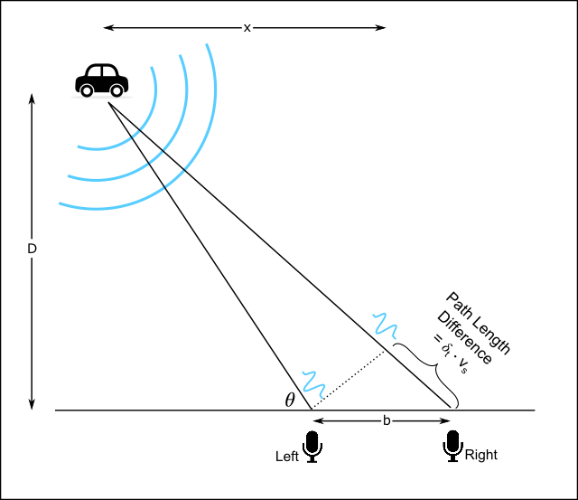
If we assume a plane wave approximation to the sound wave at the microphones, the relationship between the vehicle position, x, and the time delay becomes:
As the vehicle passes the sensor array, the measured time delay will map out a smooth function and, in principle, the vehicle speed can be extracted.
Hardware
A basic constraint for this project is to keep the cost of hardware as low as possible, so I chose to leverage a Raspberry Pi computer since the linux operating system supports stereo audio natively and USB sound cards with stereo microphone inputs are low cost. Since the speed of sound is about 343 m/s at room temperature and sea level, if the microphones are spaced 1 meter apart the maximum time delay will be about +/- 3 ms. Typical audio sample rates are 44.1 kHz or 48kHz which should be sufficient to capture a time difference of 3 ms.
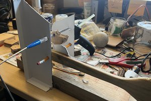
One important consideration in performing this measurement is that both microphones be identical in performance. So the acoustic response should be as close to matched as is practical, as well as the gain and phase response of the electronic signals. Some digital microphone systems have internal variable gain control and automatic noise-cancelling features which can disrupt a precise phase delay measurement such as this, so to ensure a stable gain and phase response and also minimize hardware cost I chose to build my own microphone...
Read more »
 Hugh Brown (Saint Aardvark the Carpeted)
 Vinch
Vinch
 Wenting Zhang
 nobody
Since I first posted this project, I have been working to solve an apparent bug in the USB audio capture of the linux OS. I found that the audio stream in gnuradio on the Raspberry Pi showed transient glitches in the data every couple of minutes or so. I found this happens with other audio applications like audacity as well, and only happens for the 64-bit kernel version of raspios. I reported this bug and others have confirmed it is a problem with how the 64-bit raspios kernels handle FIQ interrupts in the ARM processor. So the near-term workaround is to only use 32-bit distributions of raspios.