 ROFLhoff
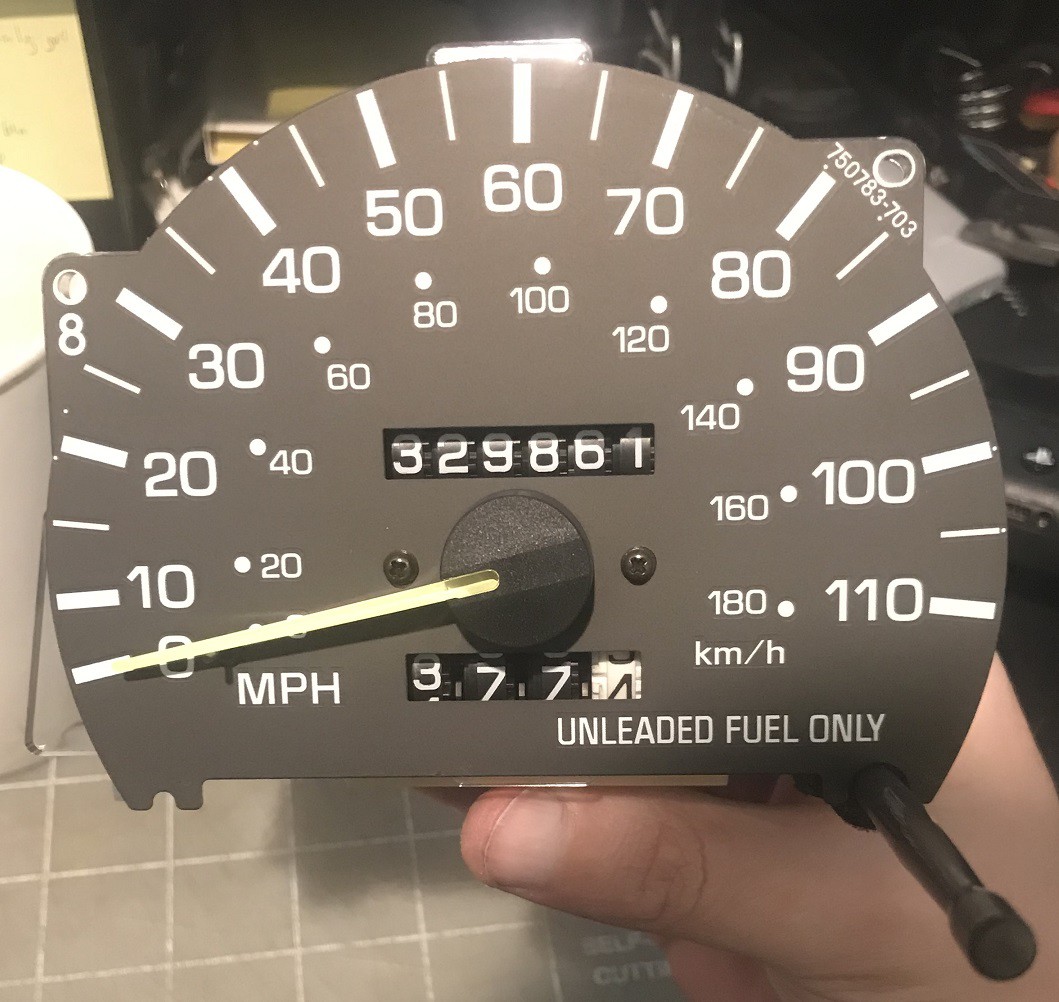
My Toyota Pickup's speedometer has been reading incorrectly for quite some time. It shows a much higher speed than it should. As an example, next to construction projects on freeways there are radar-equipped LED signs which show speed readings of vehicles passing by. I will often see readings between 60-65 mph when I drive by, but my speedometer will read 105-110 mph. And I have driven this truck enough to know at the high end of 1st gear this truck is going about 15 mph, yet the speedometer is showing 25 mph.
I also damaged the trip odometer previously. It has a plastic shaft that comes out of the dash that you'd press to reset the trip odometer. On one particular day it required more force to press than normal, and like the fool I am, I pressed with more force to reset it. Except I heard and felt a crunch, and the odometer wouldn't reset to zero anymore. In fact the numbers on the trip odometer wouldn't spin anymore. Curiously the main odometer still tracked the mileage accurately, with occasional clicking of what I assume is gears jumping because a support piece is not allowing gears to mesh.
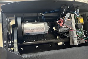
So like the curious lad I am, I took out the combination speedometer/odometer from this truck.
I'd sure like to keep this truck running past half a million miles.
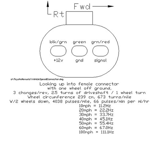
People have documented this speedometer well enough. There are two versions of this speedometer, either mechanically or electronically driven. My truck is late enough to use the electronic version. There are 4 screws which hold the gauge in place, and also provide electrical connections. Three of these connections are important. The gauge needs 12V, GND, and a signal that comes from a sensor on the transmission.
The speed sensor is mounted at the rear end of the transmission, and sends pulses as the driveshaft rotates. It doesn't matter which way the driveshaft rotates, the output of the sensor are pulses. I did not disassemble the speed sensor, but I assume there is a rotating magnet that causes a hall effect sensor to short the output to ground. All that needs to happen to interface with this is to use a pullup resistor and detect every falling edge or rising edge as a fixed distance traveled. Assuming the use of the stock differential and stock size tires, the sensor is geared in such a way that every 4000 pulses/falling edges as a mile traveled.
The following image is one person's findings, but I did spend some time driving a known distance several times and tracking pulses, and I am getting closer to 4000 pulses per mile rather than their claimed 4038 pulses per mile. Do note that I am using 205/70/R14 tires inflated to 35psi, which comes out to about 201.9cm circumference instead of their given 239cm.
If all that's needed is an odometer, we could simply keep track of pulses and divide that by 4000 to get mileage. If we store two sets of counted pulses where one is reset to 0 by pressing a button, we get a trip odometer too.
To get an indication of speed, we also need to keep a fairly accurate time base. Since there are 3600 seconds in an hour, we have a factor of 4000 "pulses per mile" over 3600 "seconds per hour". Shifting units around, we arrive at 4000/3600 "pulses per second per mph".
With this calculated factor, I created a circuit that output a series of pulses, a square wave generator with adjustable frequency. I used the classic 555 timer for this.
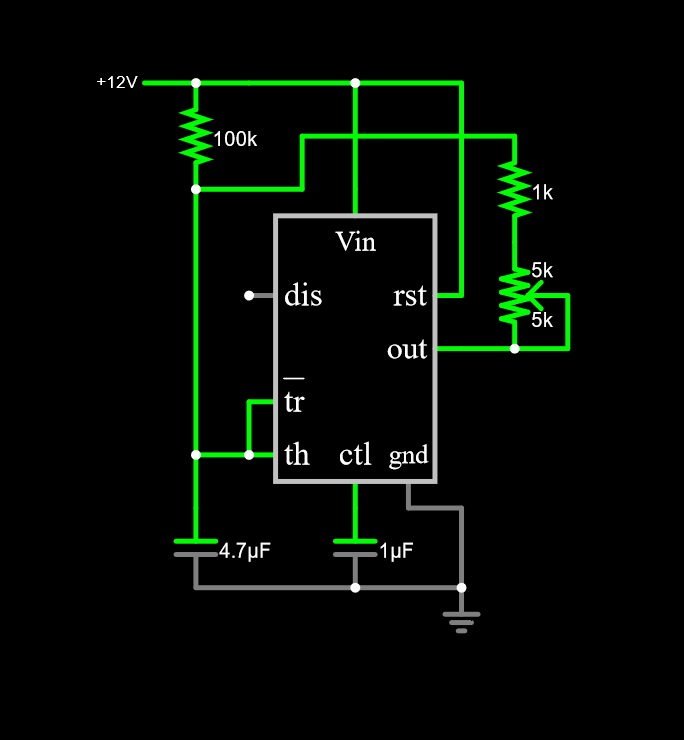
With the given 10k potentiometer, I could generate square waves from about 12Hz to 125Hz. When this frequency range is fed into the speedometer, we should be seeing the needle move between 11mph and 112mph.
I was hoping that this speedometer was okay, but when I gave it an input signal with frequency of 31.2Hz, the needle moved to roughly 45mph instead of a proper 28mph reading. This lines up with the previous observation of 60-65mph actual speed being displayed as 105-110mph.
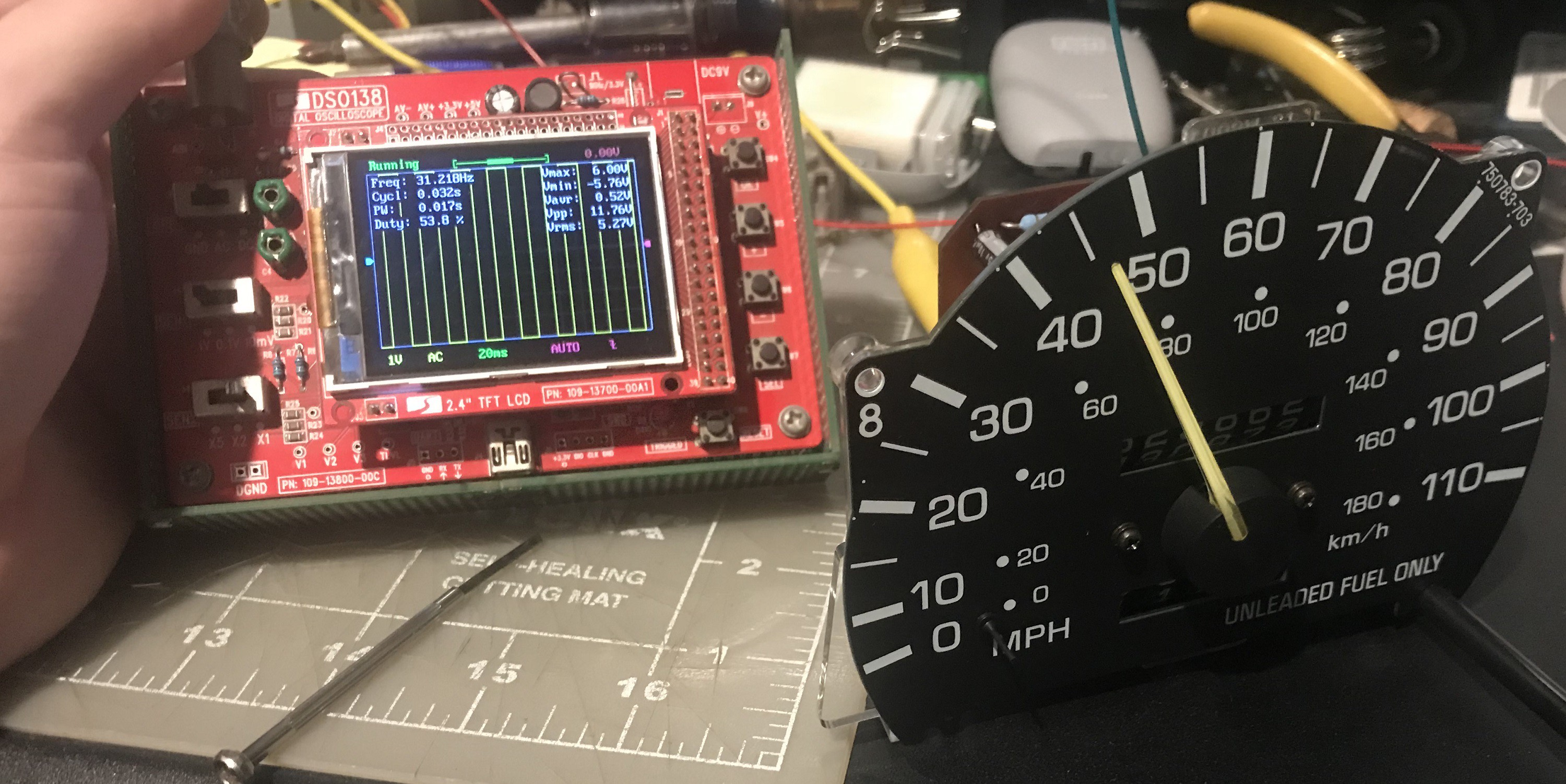
So something is definitely wrong with this speedometer. So let's look at the speedometer in more detail. Here is the backside of it....
Read more »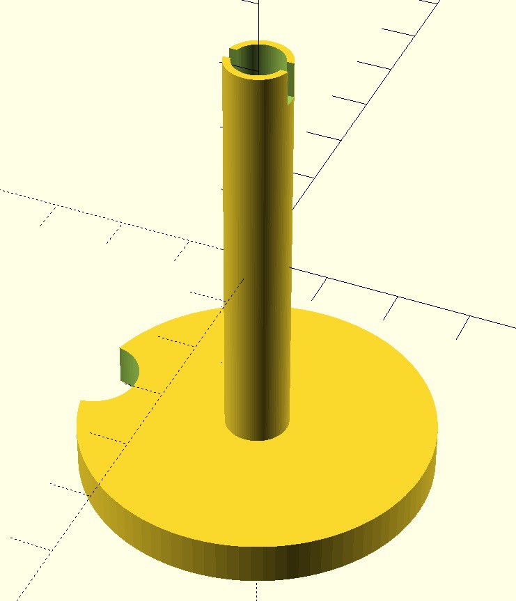


 Enzo Lombardi
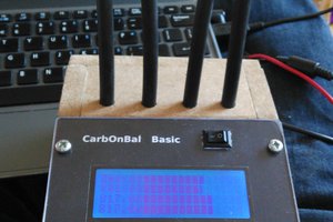
 dennis
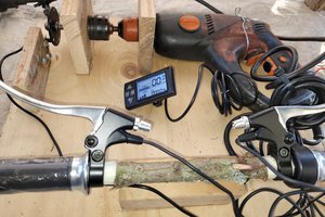
 junkotron
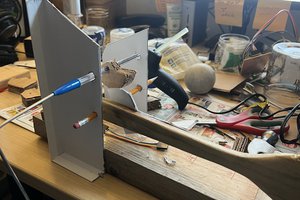
 Hugh Brown (Saint Aardvark the Carpeted)
Hope you see this comment, I can't seem to continue the reply chain.
You likely have a broken piece of plastic in the trip odo. It's a fairly tight workspace with the PCB installed, but I don't recommend you remove it unless you have to. Hopefully it's a clean break and not a floating piece to wiggle back into the mechanism.
The prompts I gave ChatGPT were simple. I had it do one thing at a time. In the initial prompt I told it to make an openSCAD model, at first it was a cylinder shape, then to cut a slot, cut a cylinder of smaller diameter than the shaft, add a large diameter cylinder on the other side, cut a small circle from the edge of the large cylinder. Other than messing up the units, it output valid code.