 Jeroen Delcour
This is a project I did in October 2022. I documented the design & build process mainly for myself, but when I saw the Gearing Up contest I figured it was time to upload my first project to Hackaday. I've kept the documentation mostly unaltered, so you can see how the project developed, with all the trials and tribulations that such projects have. I've added some logs about things I remember but apparently didn't write down at the time.
Requirements
- Min RPM: <500
- Max RPM: >6000
- Programmable spin speed and time
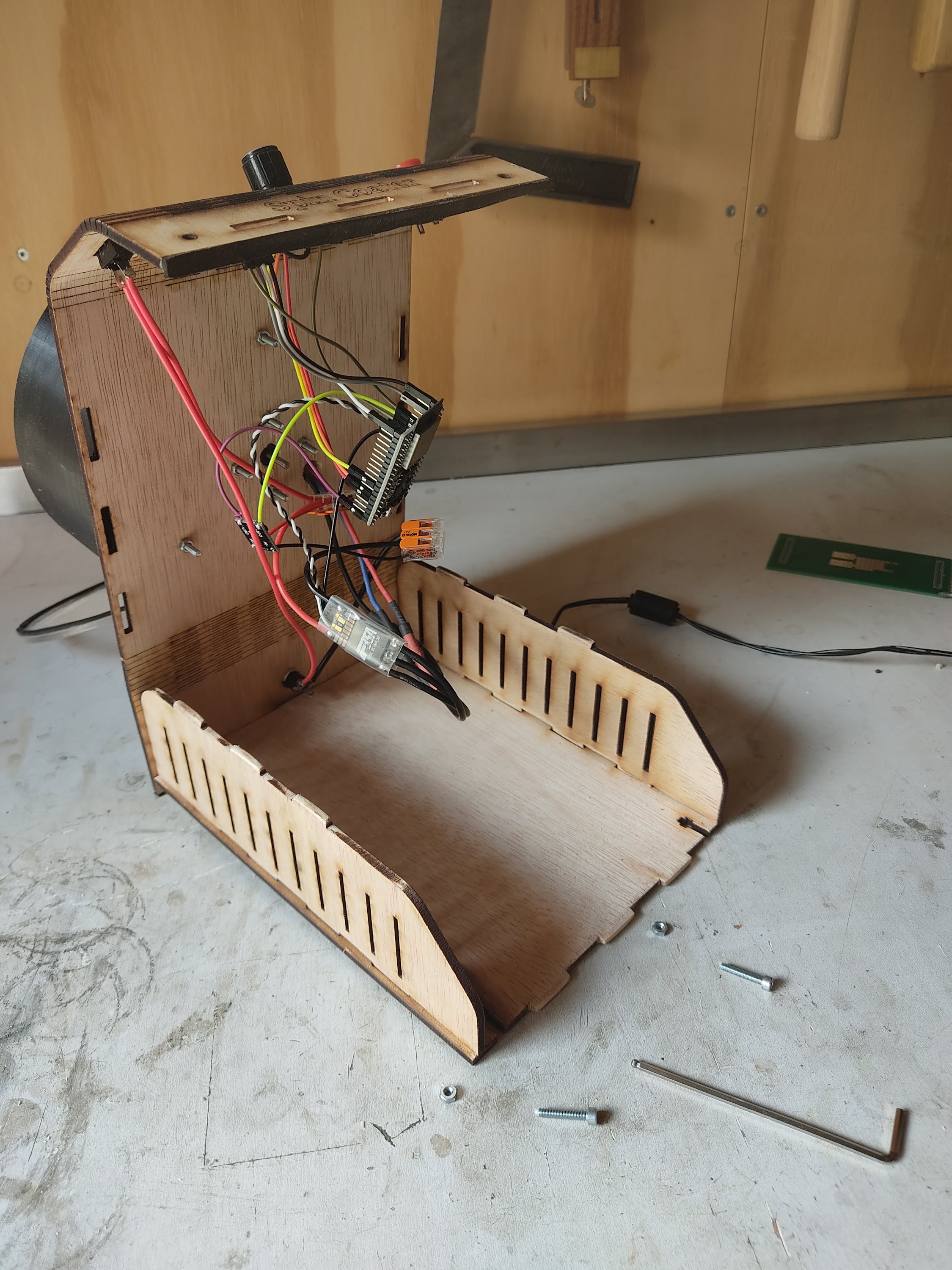
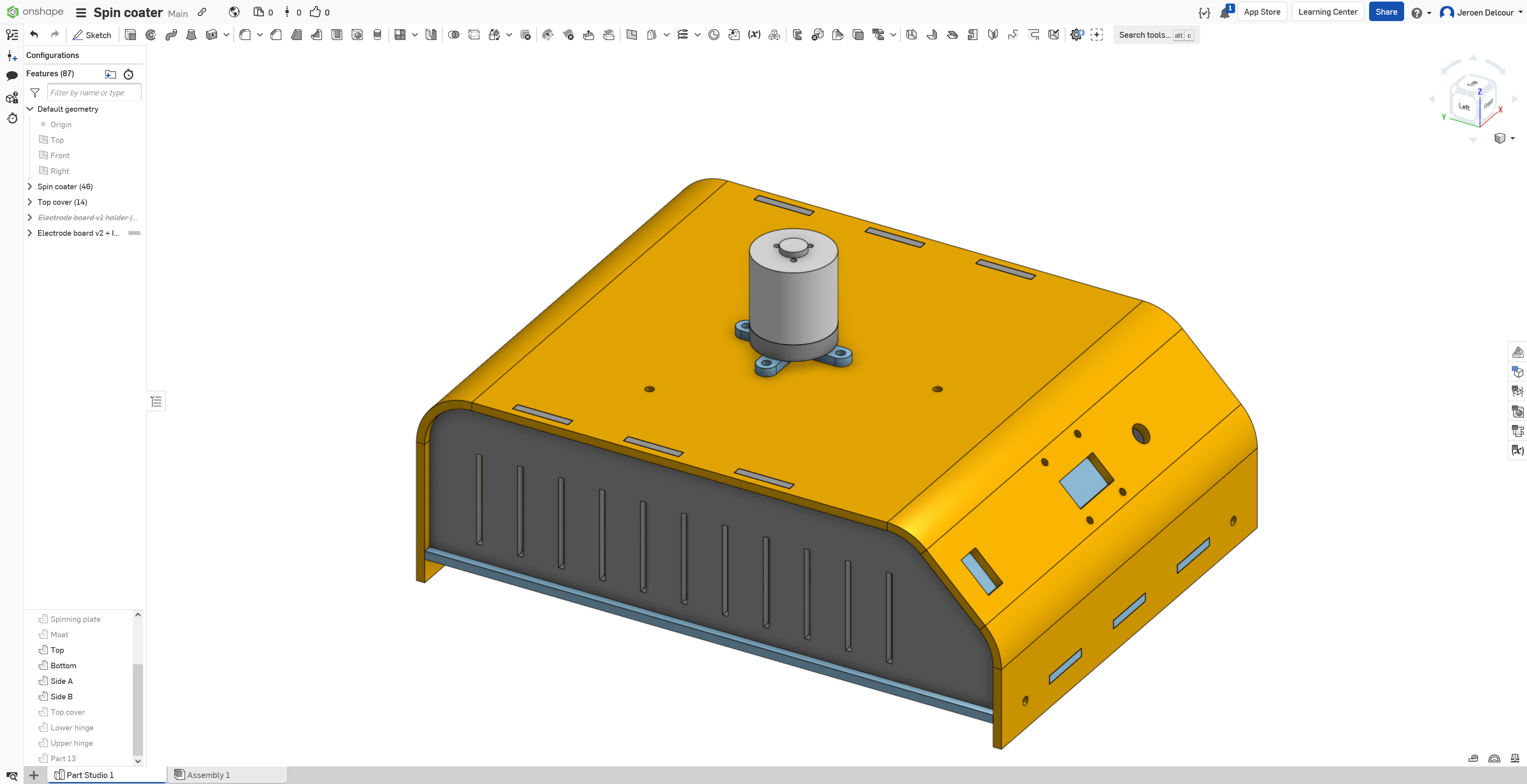
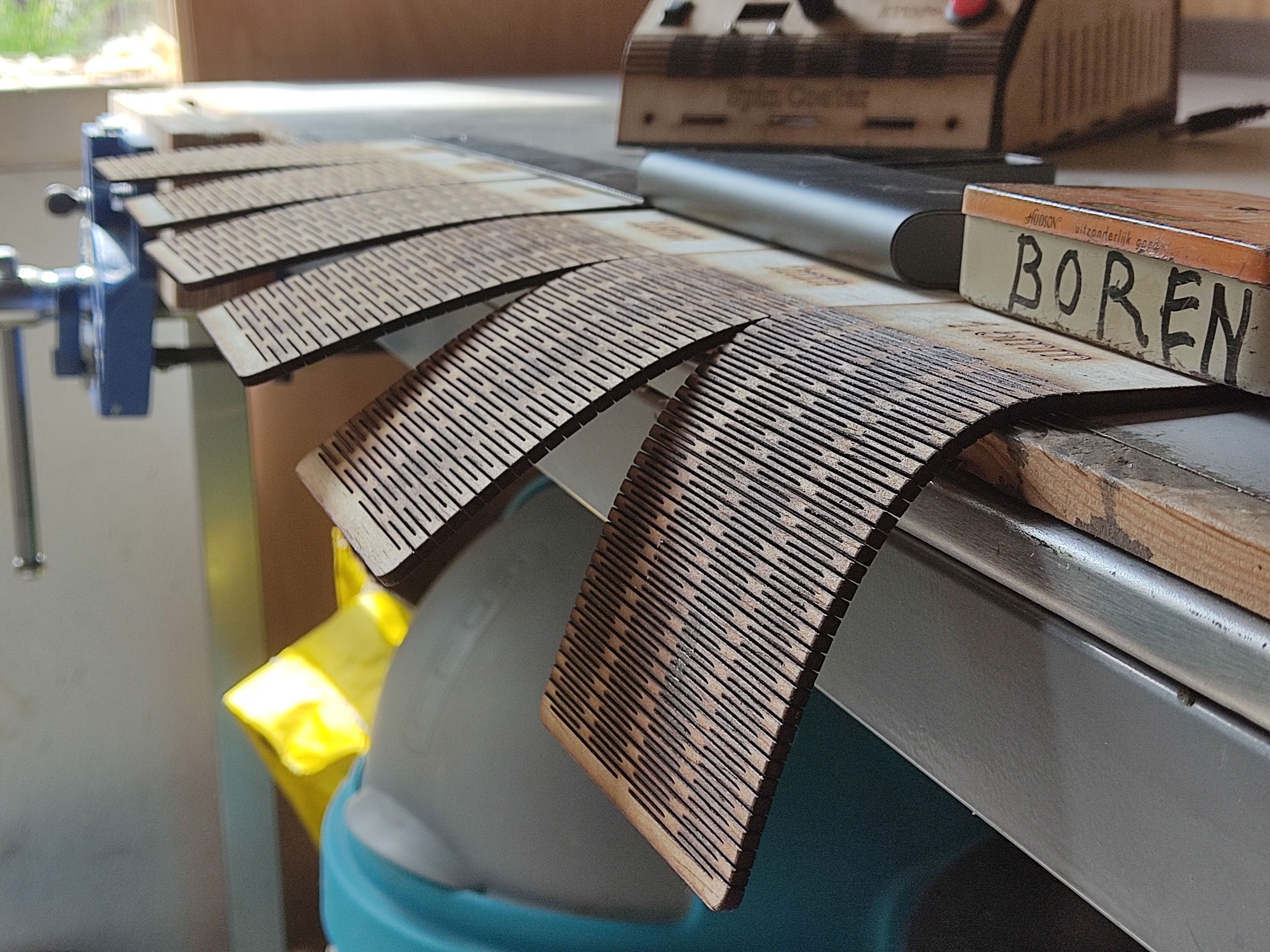
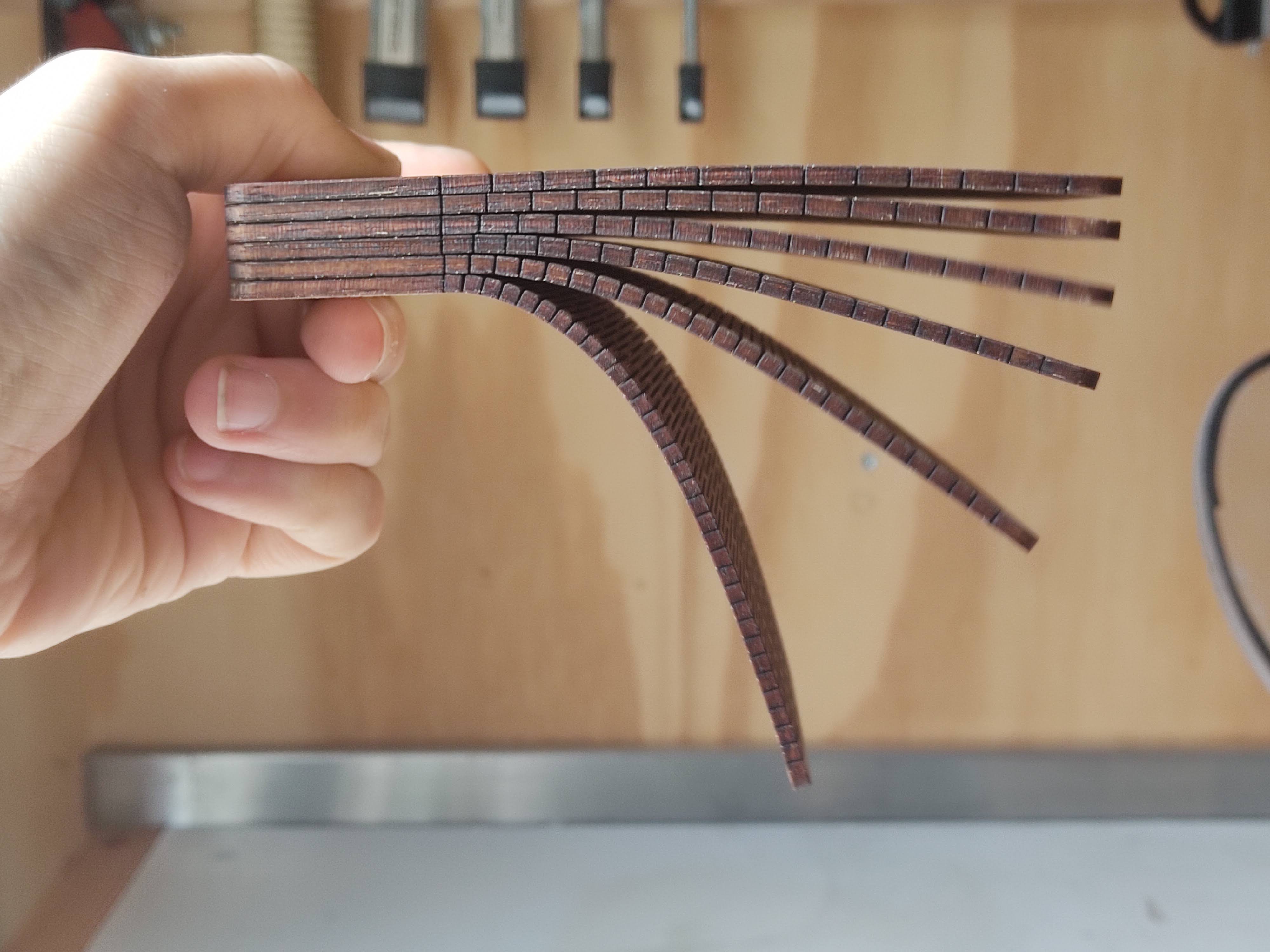
- Enclosure that catches flung liquid
- Display that shows RPM and timer
- Buttons for control
- Adjustable chuck that can fit several parts, but at least:
- 50x50mm glass square
- 105x50mm PCB (ideally with header pins sticking out on the bottom)
Inspiration
Parts
(The parts I ended up using are in bold)
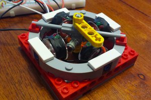
Motor + ESC
Brushless motors and ESCs for drones or RC cars are cheap (€10-20 each). Most drone motors spin much faster than we need, so we should pick a slow (<2000 Kv) motor to reach the minimum RPM we're aiming for.
It would be nice if the motor had tapped holes in the rotor, then we could bolt a simple 3D printed or laser-cut piece directly to it as a chuck. A threaded shaft would also work but would probably need an adapter. A D-shaft (AKA shaft with drive flat) would be a last resort
Motor options:
- Racerstar BA2216 1250kv (€21)
- Flashhobby D2826EVO 2208 930KV (€26)
- Racerstar BR3536 950KV (€21)
- Sunnysky X2216 1250KV (€24.78)
ESC options:
- 35A BLHeli_s ESC (€14)
- Skystars Slim40A BlHeli_32 ESC (€18)
- T-Motor F35A 32bit 3-6S ESC (€28.95)
Motor + ESC options:
Speed control
There’s lots of approaches to this with varying hardware complexity and software complexity.
The old BLHeli ESC firmware had something called governor mode or closed-loop mode, where the throttle input was interpreted as a desired RPM and an internal PID kept it at that RPM. However, this firmware is quite old now and the newer versions don’t support it.
The newer BLHeli_32 supports something called bi-directional Dshost, which is a protocol that allows the ESC and the flight controller (which in our case is a microcontroller) to communicate over a single wire. When the ESC receives a (digital) throttle signal, it sends back an eRPM signal that would allow closed-loop RPM control. This is supported in newer flight controller firmware like Betaflight. But to use this on a bare microcontroller, we’d have to implement the protocol ourselves. The protocol is described nicely here, and it may be possible to use the ESP32’s RMT to implement it, but it’d have to be implemented in C because the ESP32 MicroPython firmware doesn’t support receiving signals using RMT.
There’s also some ESCs that support sending telemetry over a separate wire. The protocol seems simpler and it could maybe be implemented using UART.
Note that all BLHeli firmware also supports the old, simple 1-2ms pulse width protocol. Which protocol is used is automatically detected on power up.
Options for RPM sensors:
- Reflective sensor, e.g. QRD1114 or QRE1113 (€3.50)
- Brushless ESC RPM sensor (€5.87)
Power supply
Drone motors are designed to work with LiPo batteries, typically 2~4S (7.4~14.8V). The other electronics like the microcontroller and the display need 5V and don’t draw much current (<500mA). Perhaps it’s better to first run the motor with a bench power supply to see what the current draw is.
Some ESCs come with a built-in 5V regulator (called a BEC or UBEC). Otherwise, these are the options:
We’ll also need a power plug:
- 5.5x2.1mm DC power plug (€3.27 for 10)
Microcontroller
Any modern microcontroller like an ESP8266, ESP32, or Arduino Nano will probably work...
Read more »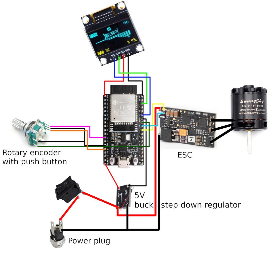


 Adam Smallcomb
 Joseph Marlin
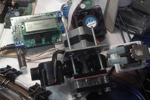
 James Newton
 Quinn
Quinn
The link to the code is at the top, but I agree it's not very visible. I've added it to the top of the description now as well.
I've had several requests for a wiring diagram, so I've added one in a project log. I hope it's clear.