Nelson Phillips
-
Version 3
11/19/2018 at 08:07 • 0 commentsThere was numerous problems with the previous version 2 of the dust extractor system design. This log documents an attempt to address these and adds an addition type of vacuum integration.
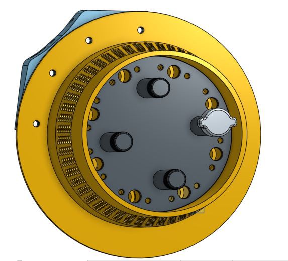
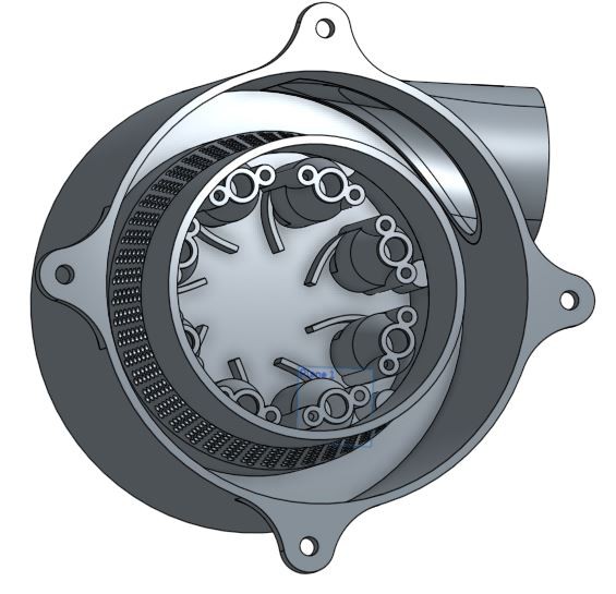
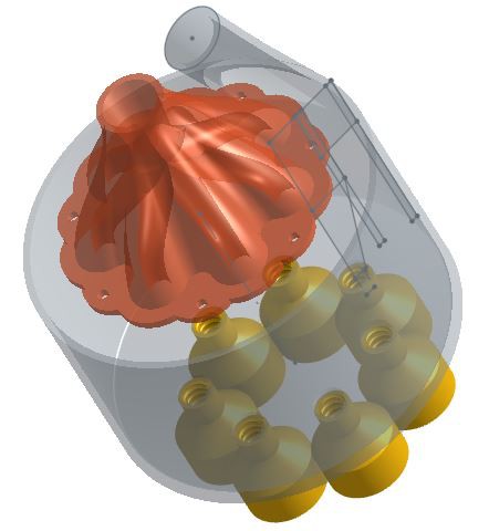
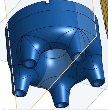
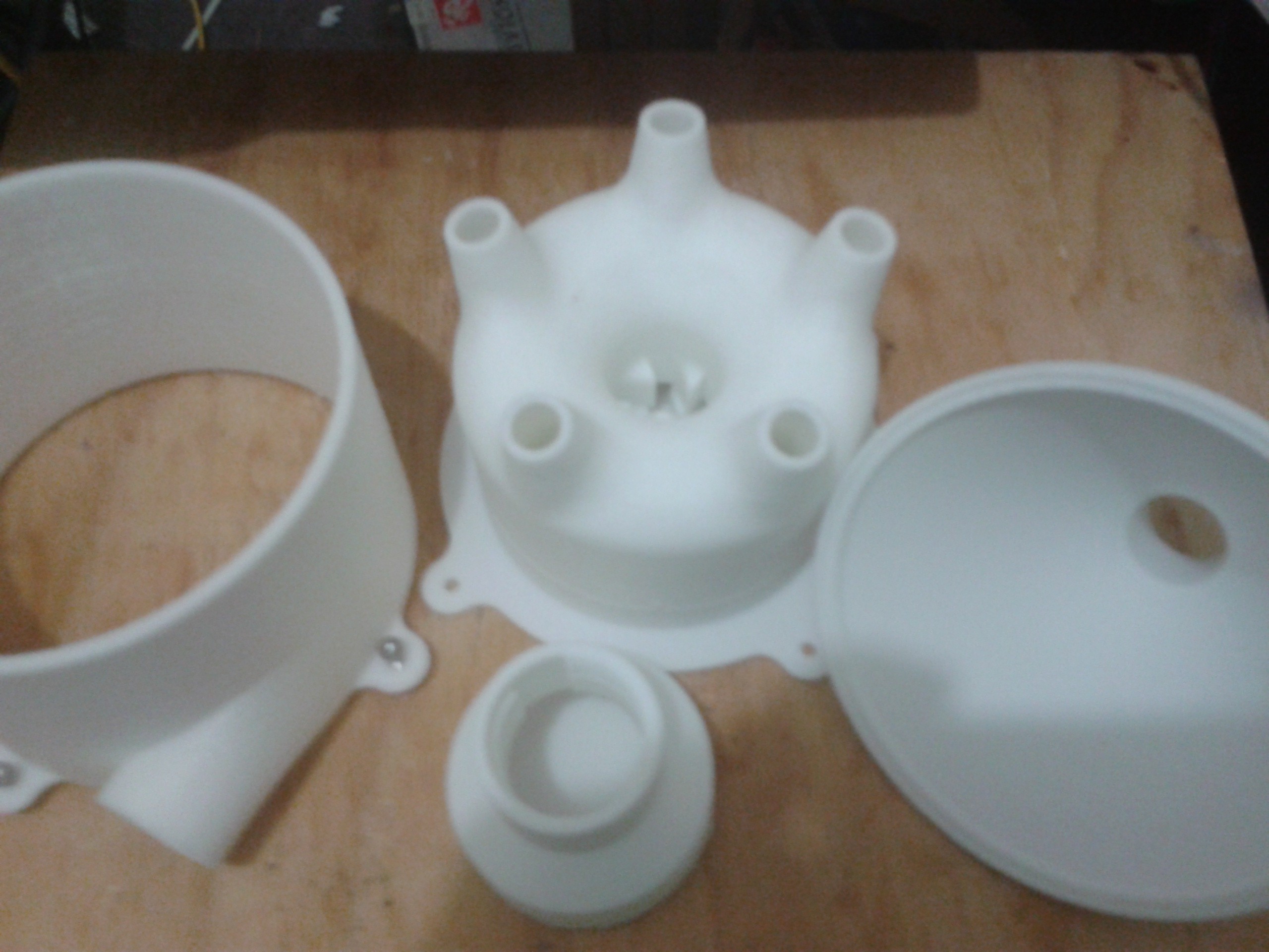
One of the problems with V2 was the way the fine particulates got collected and the manner of integration. The idea of V2 was to use the fine particulate collector was used to fasten the system together. There was not anything wrong with that method, however the execution was a bit difficult. The major change to this version, V3, was to do a better job at the fastening integration. It was achieved by introducing an inner holding piece sealing the fine particle chamber and attaching the external shell.
![]()
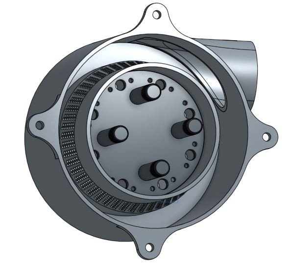
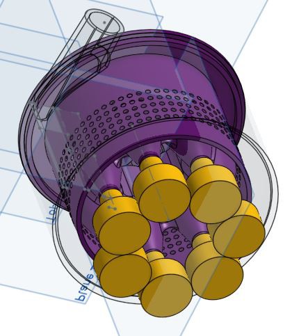
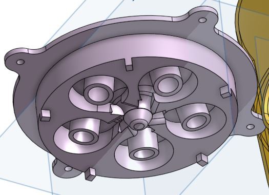
The grey part is the inner holding structure. Generally the integration of the system is much better with all the functions of the cyclonic dust extraction process more solidly defined.
- Larger debris collected in a larger volume further away from where the inlet to the main cyclonic chamber is located.
- The cyclonic chambers function is now separate from every thing else and further redesigns can easily done, say increasing the number of cyclonic cells or their radius.
- Release nuts can now be easily used and there are fewer of them.
![]()
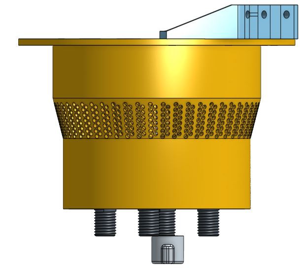
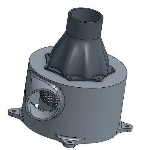
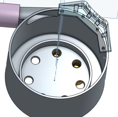
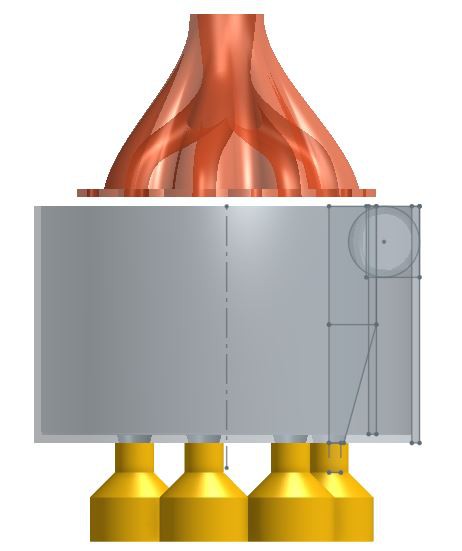
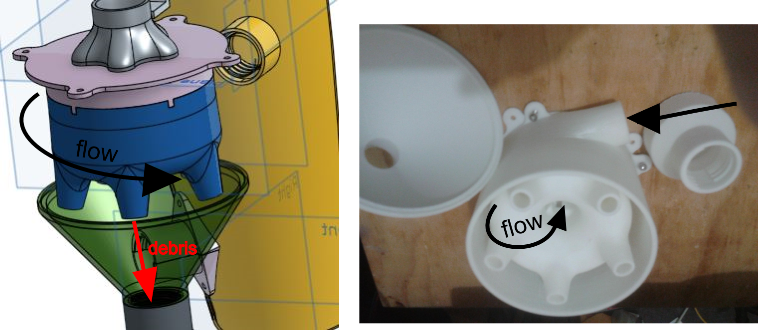
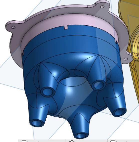
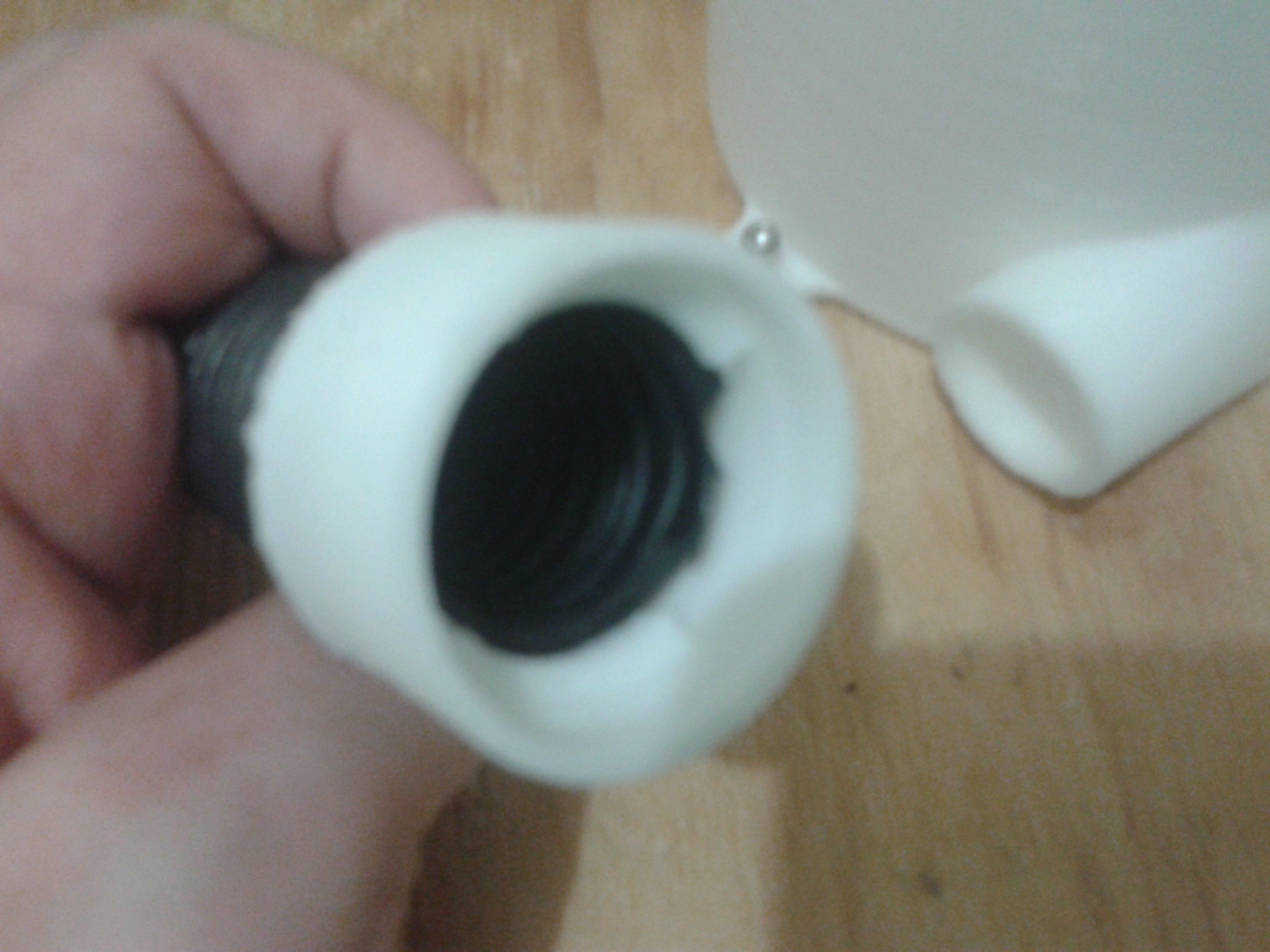
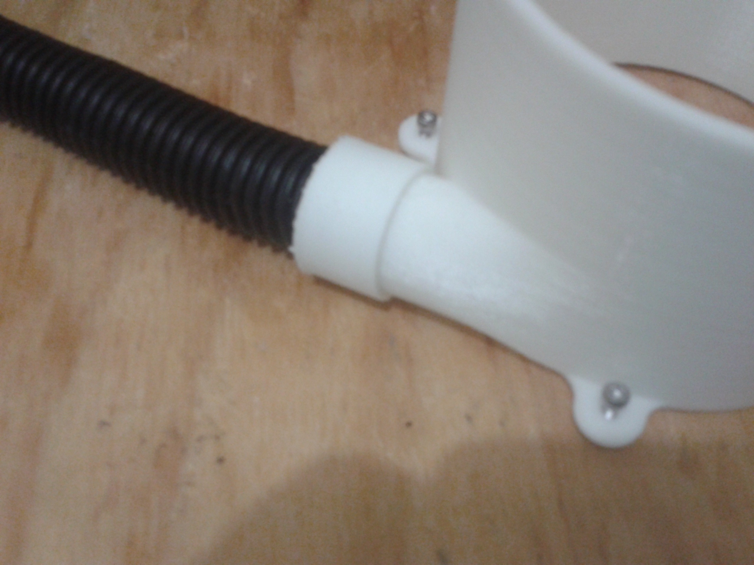
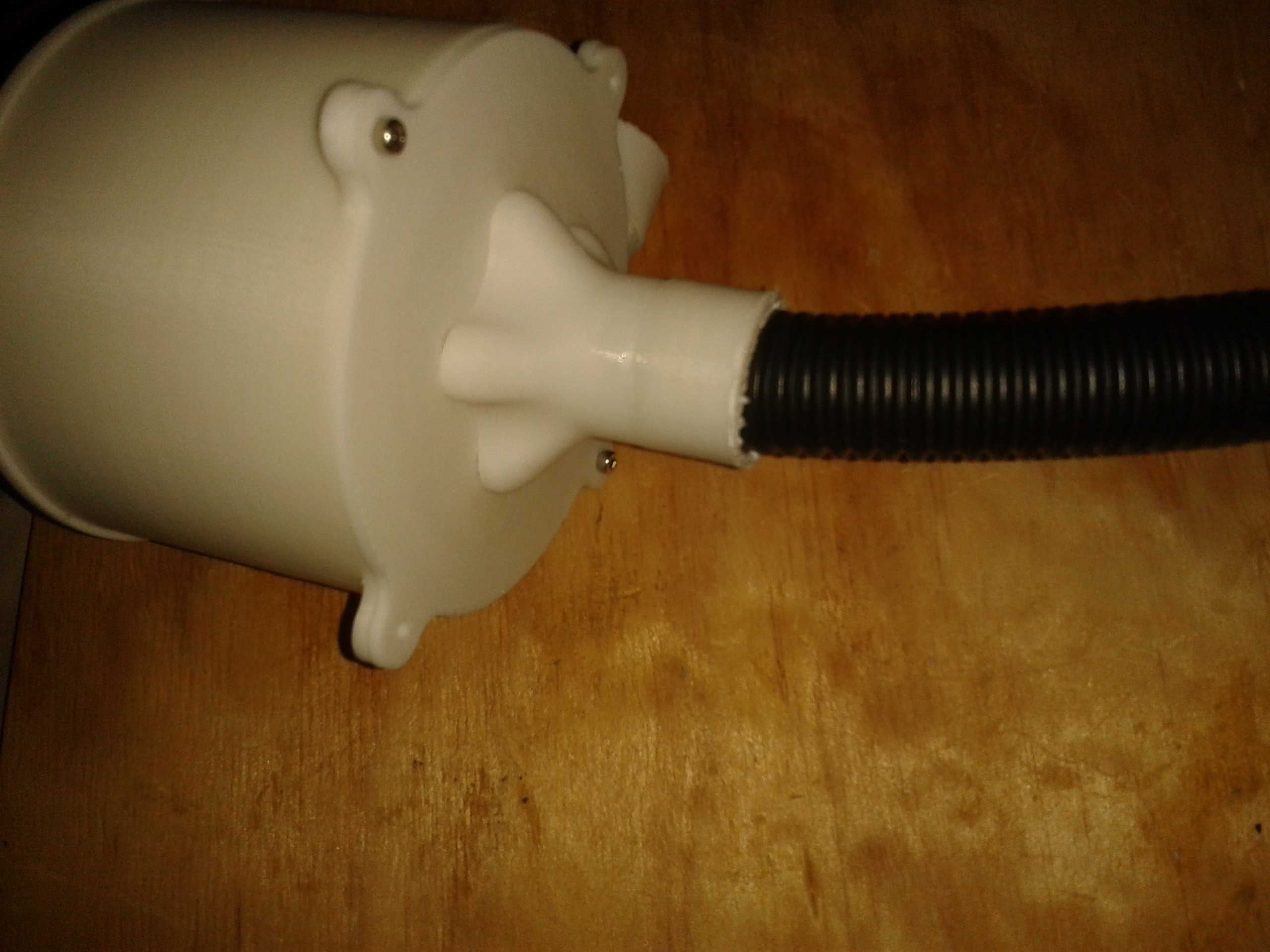
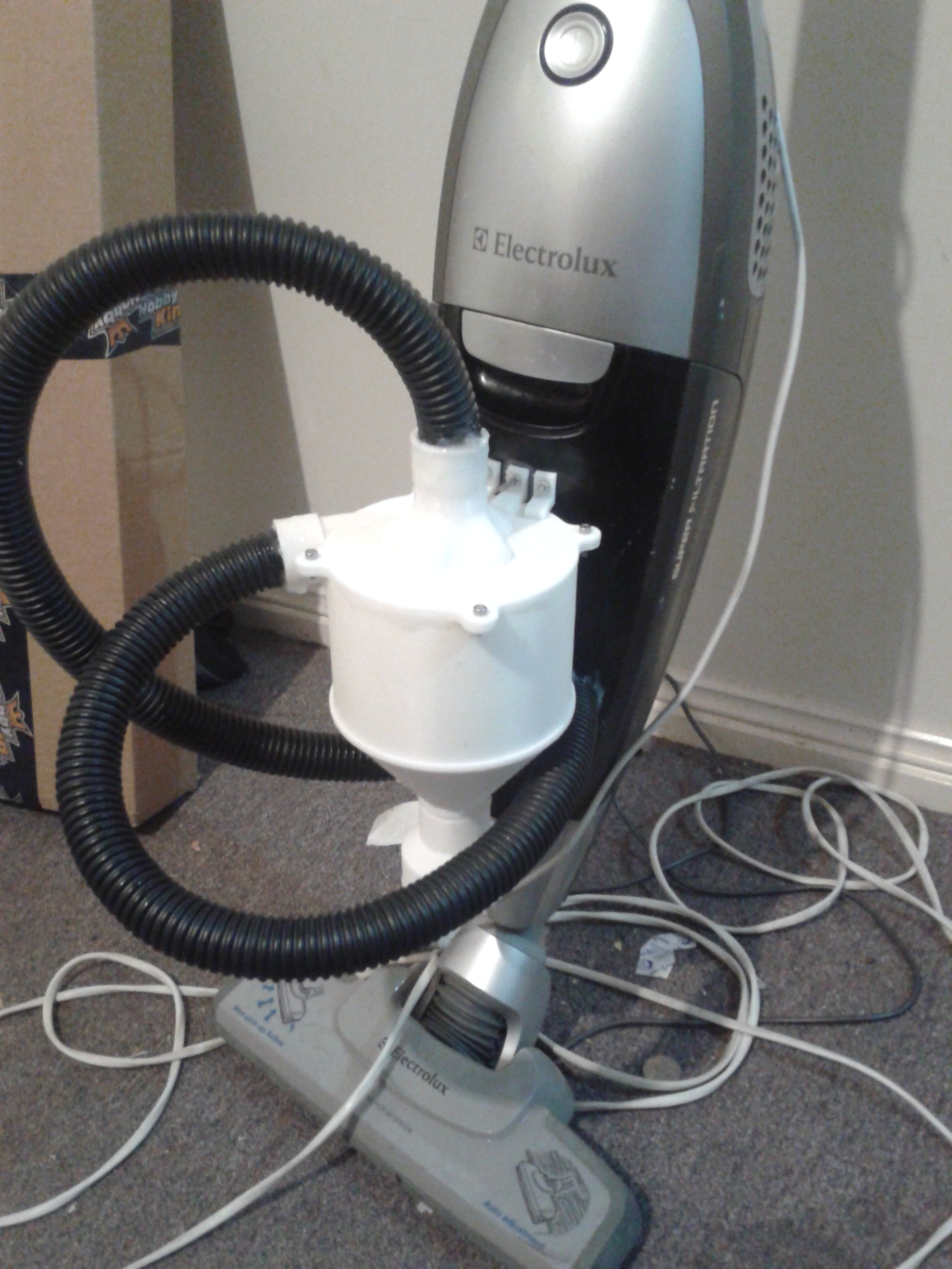
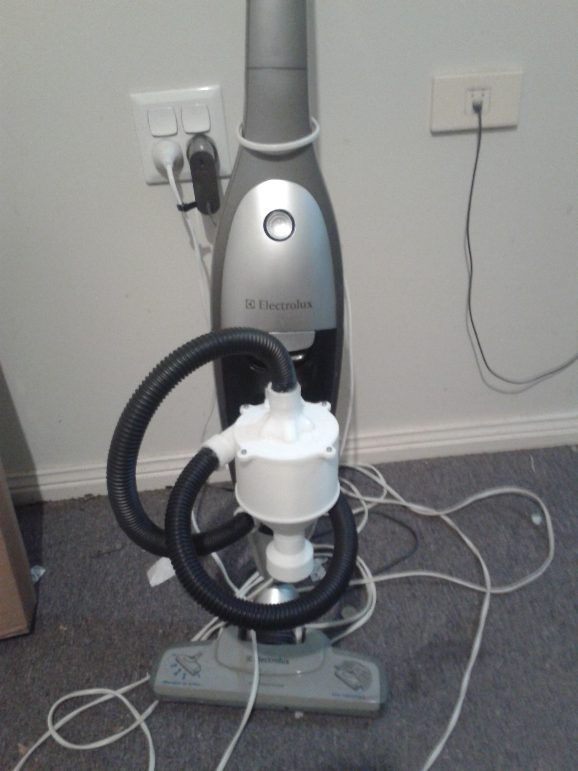
Bucket Attachment.
Typically dust extractors are located in wood working spaces with large volume to hold chips of wood. The method of the systems integration allows the system to be mounted on a buckets lid dramatically increasing the volume of the large particle collection, more suitable for outside use.
![]()
![]()
![]()
-
Shell modification
02/20/2018 at 08:04 • 0 commentsA slight improvement in the shell for the specific purpose of emptying the detritus. A extrusion was added to the upper surface of the base. After vacuuming the collected material tended to spill out the bottom holes that attachment collectors fastened the shell. This is to prevent this small spillage.
![]()
-
Funnel Replacement & Observations
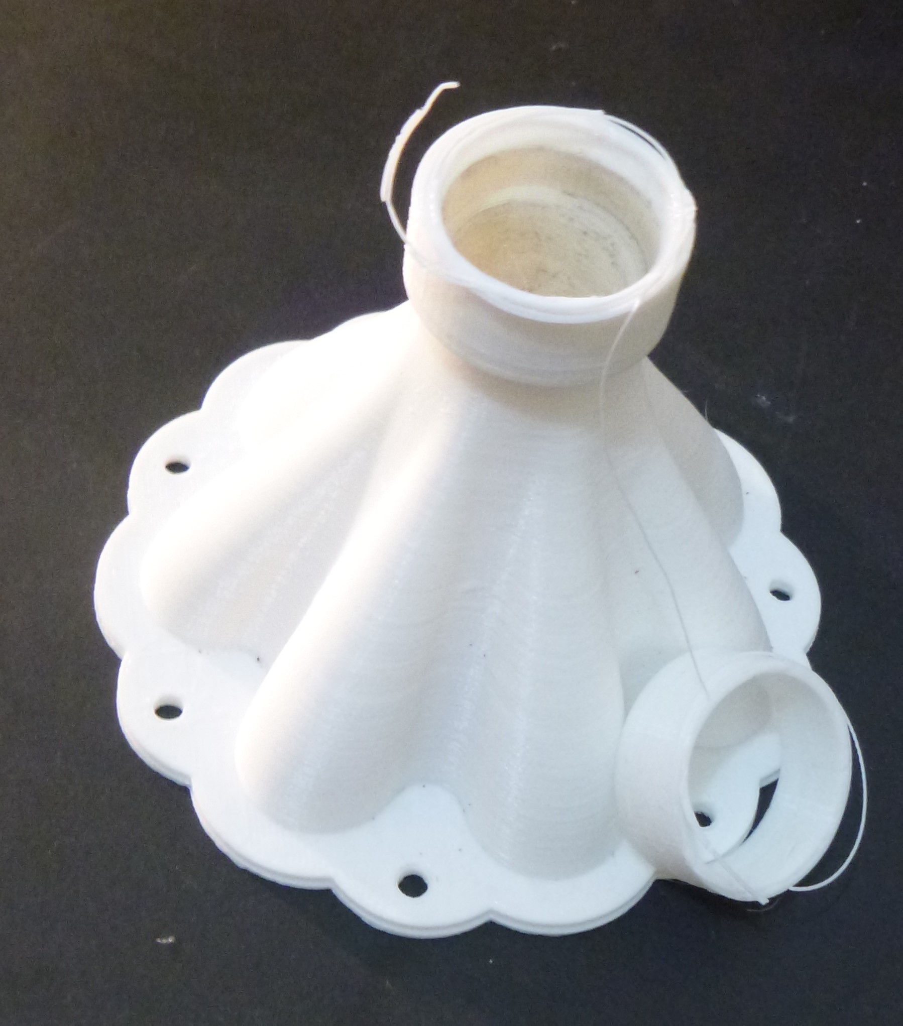
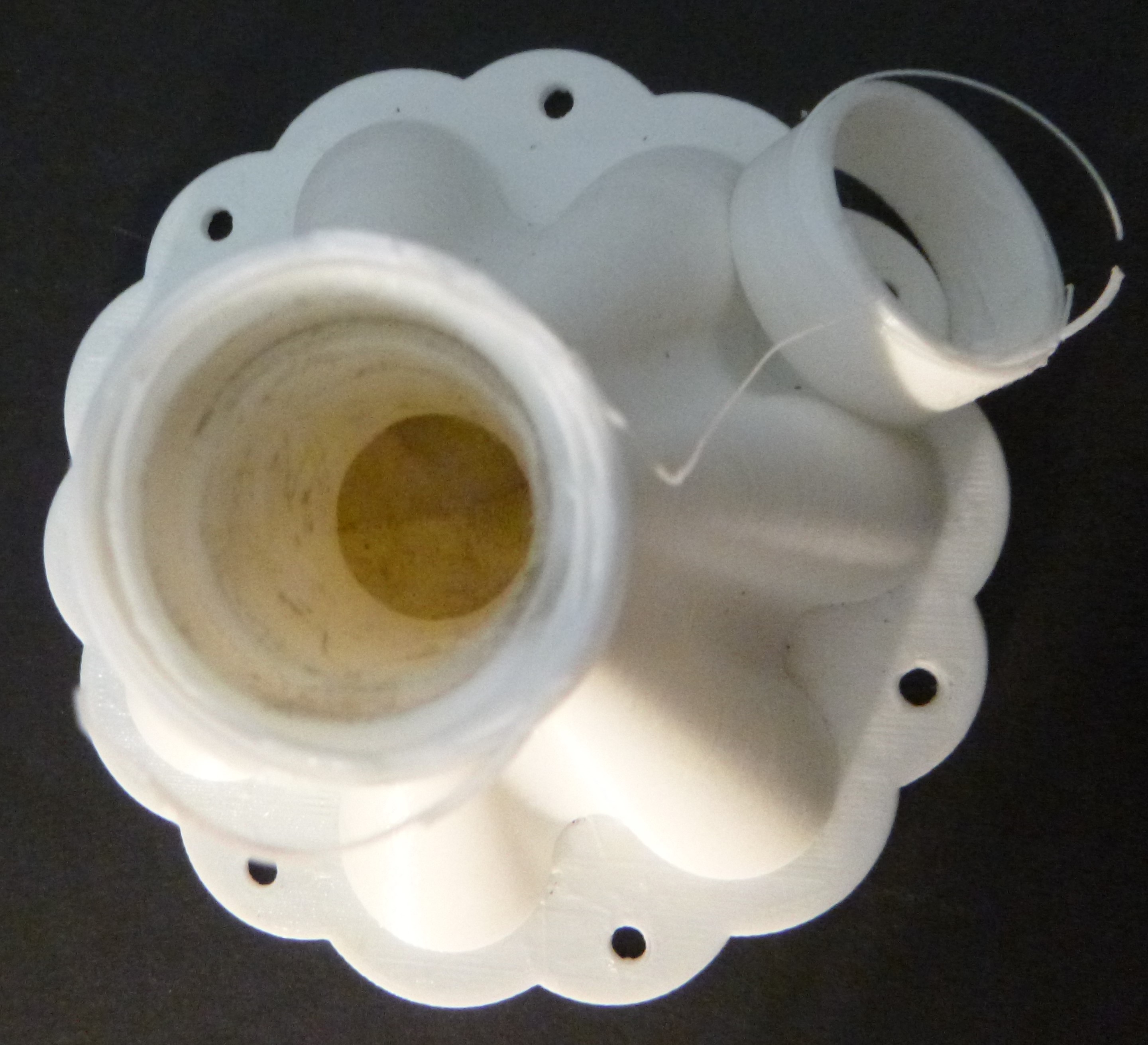
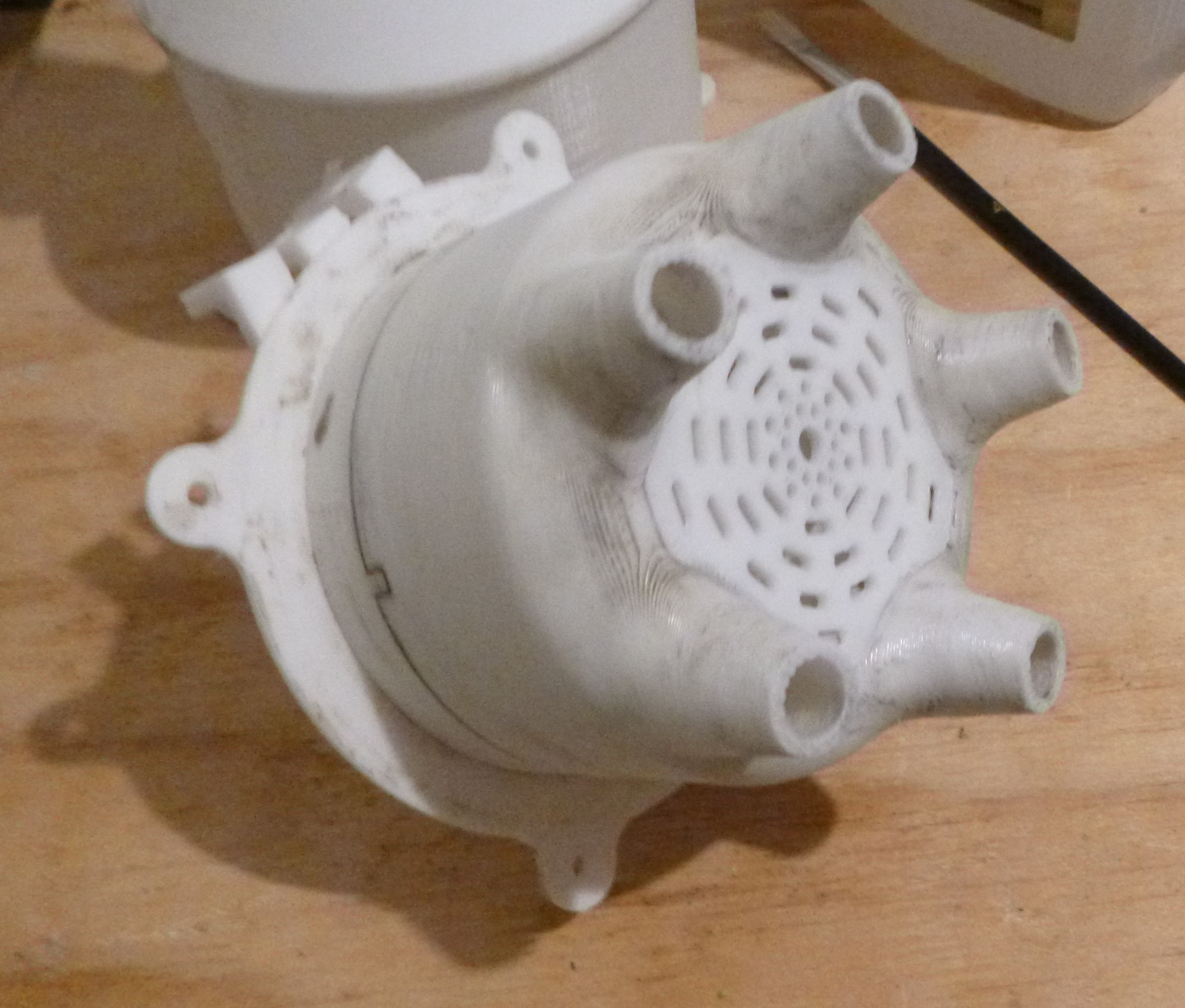
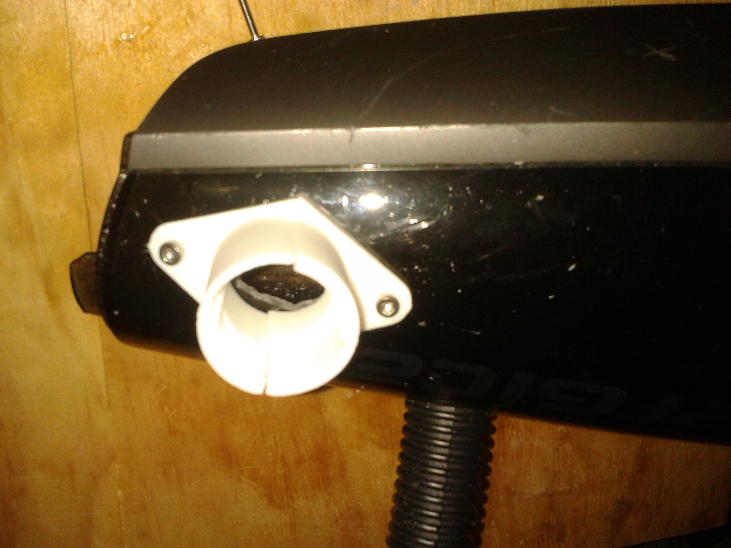
12/11/2017 at 07:15 • 0 commentsIt seems that the funnel outlet was not strong enough and broke under very little use. This was beefed up and in the process had the internal material removed, which make more sense for a number of reasons. There was a constriction made through poor design and the material was reduced significantly.
![]()
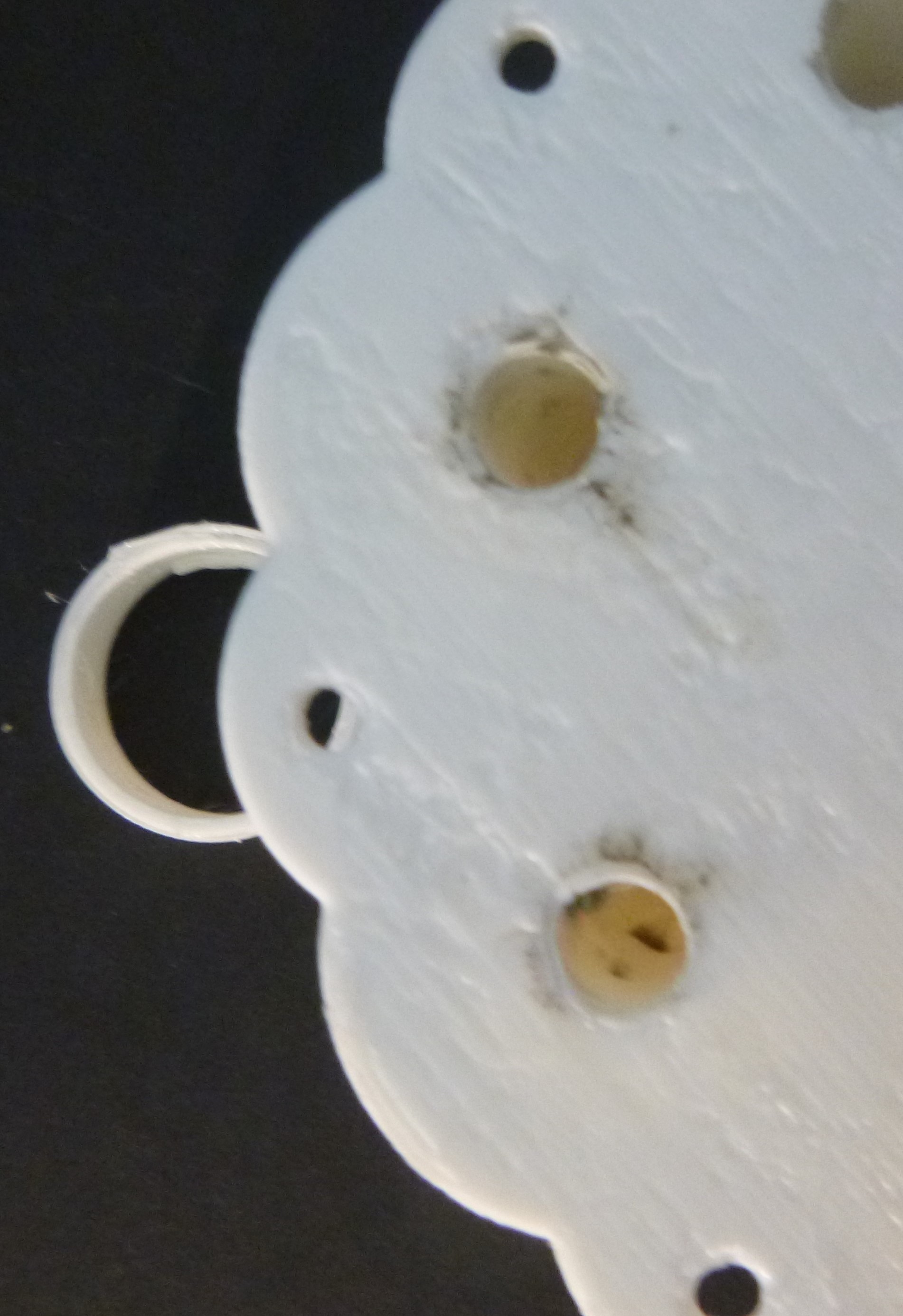
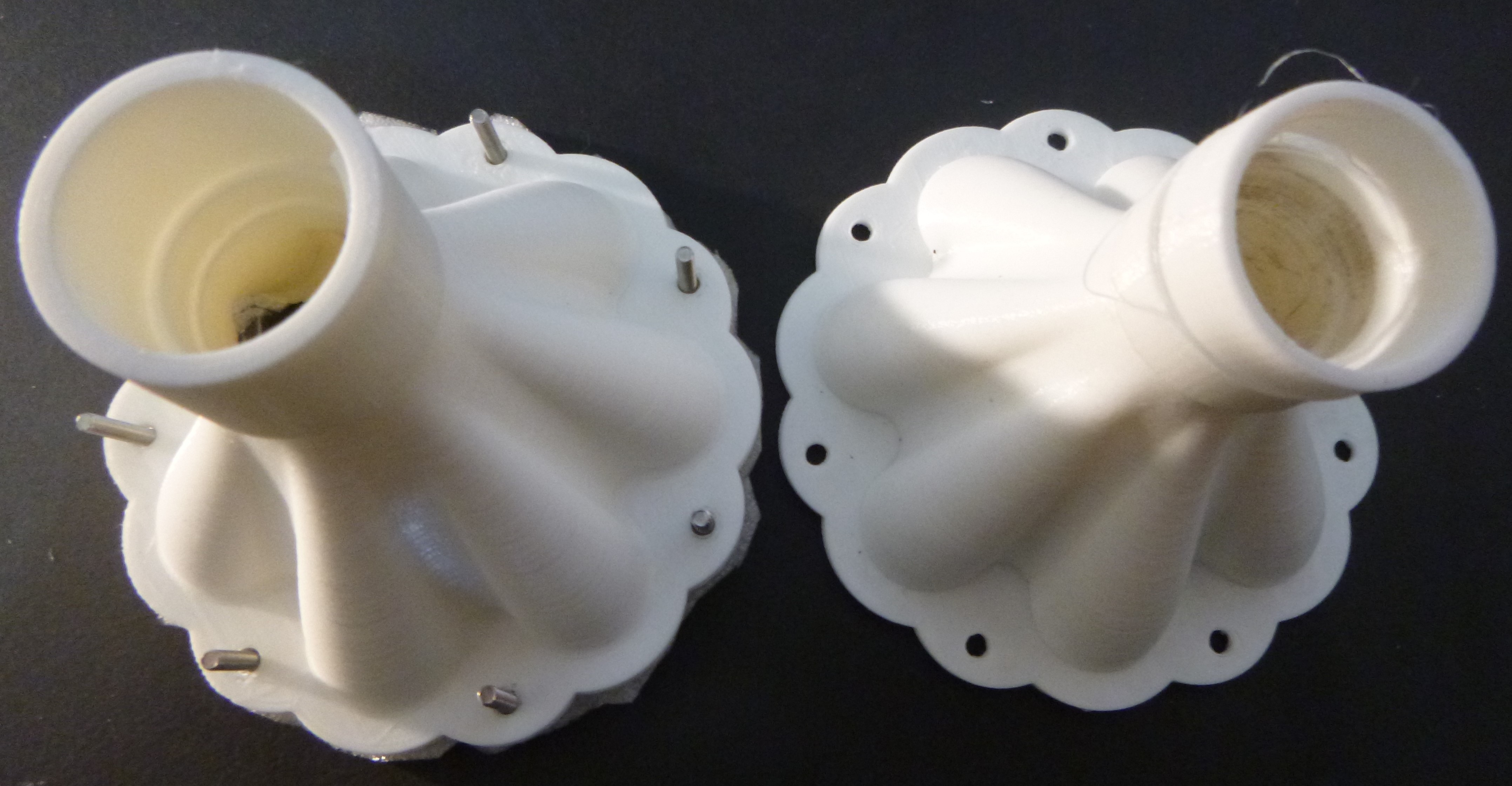
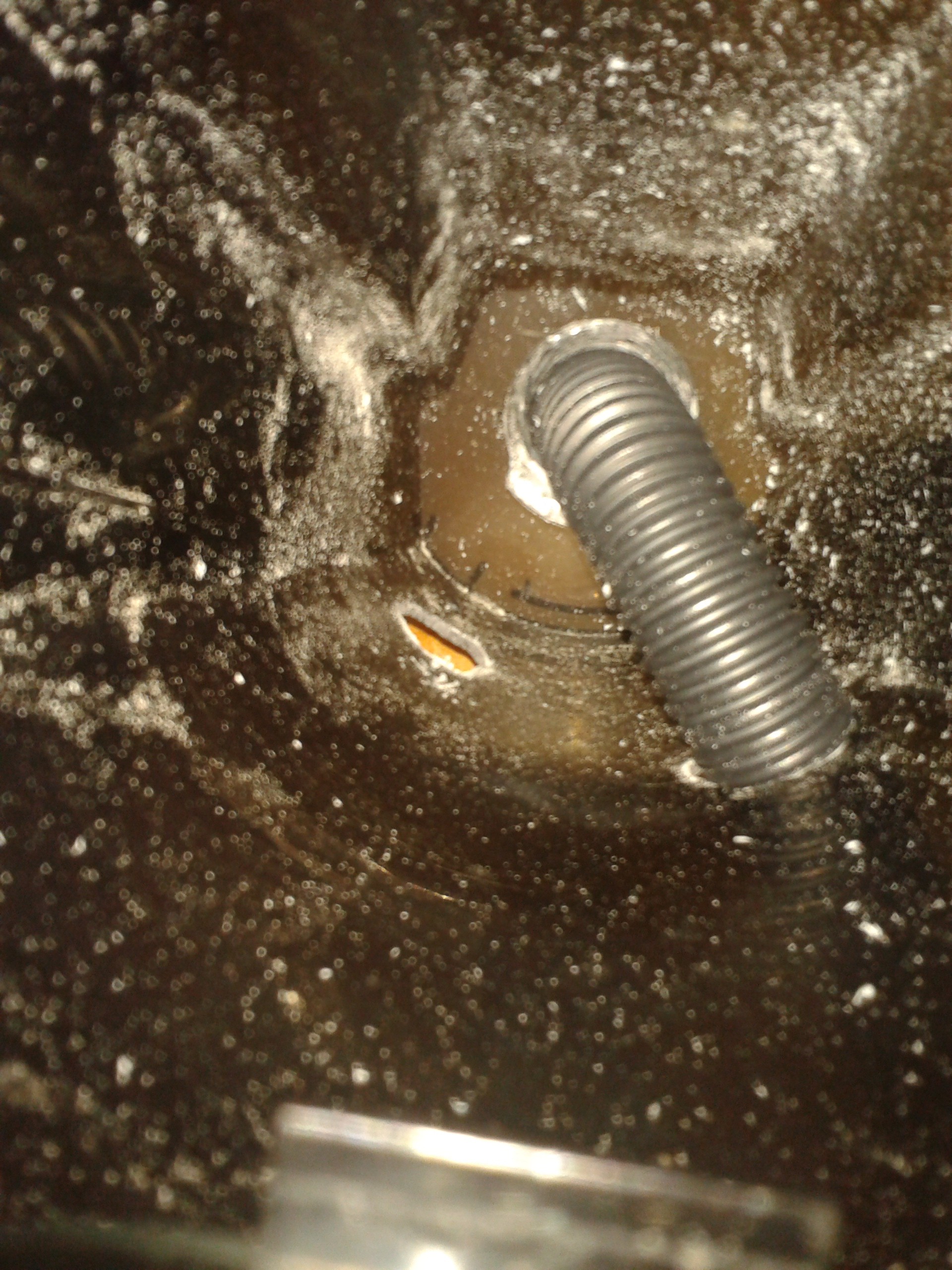
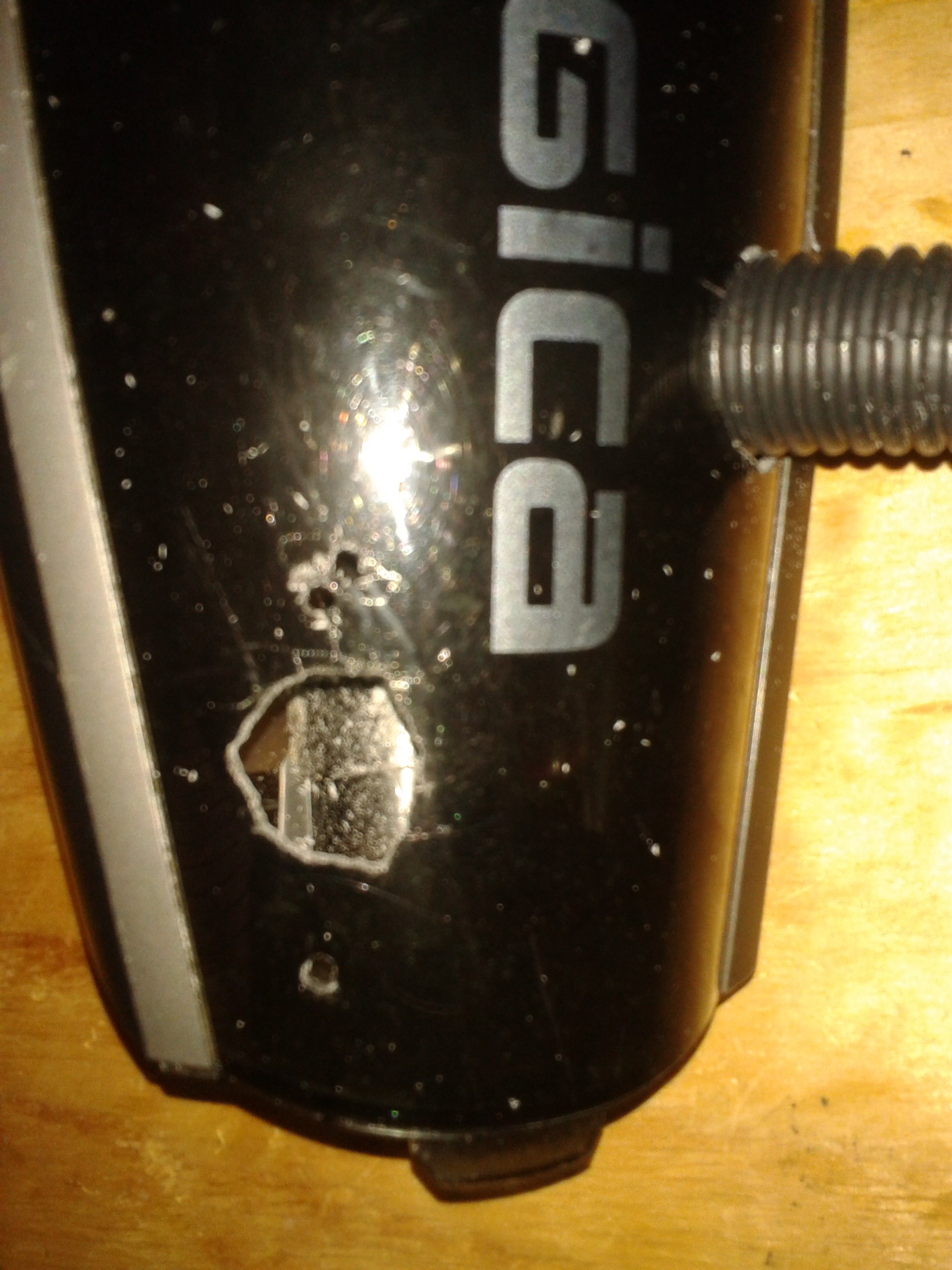
Some observations from the use, about one hour, is the amount of dirt on the outlet of the cyclonic separation section. Knowing that this system will not remove all the dirt particulate from the air it still seems like a lot. There seems to be a small amount of fluff catching on the inherent print imperfections that might be seen in the images below. However, it also might mean that a Hepa filter that all systems like this run is clearly needed.
![]()
![]()
![]()
-
Iteration II
12/03/2017 at 06:21 • 0 commentsThe second iteration of the cyclone dust extractor takes the first iteration and improves upon that. This seems to have been successful and the 40 hours that this took to print was not a waste of time.
![]()
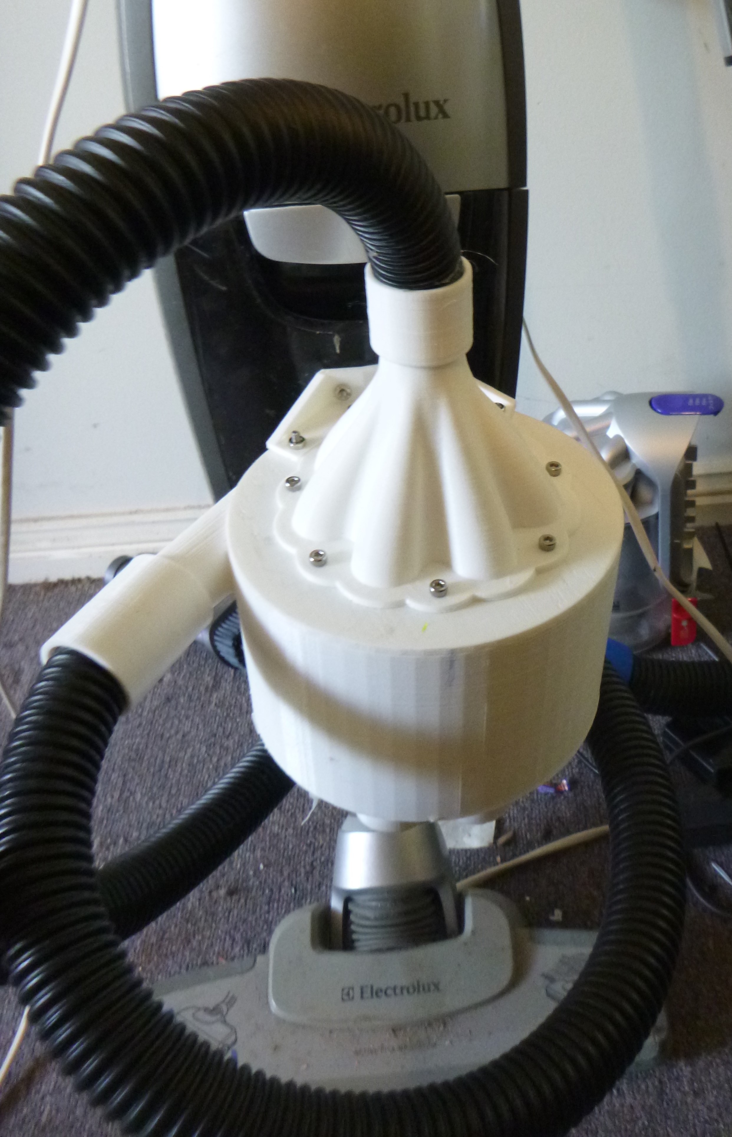
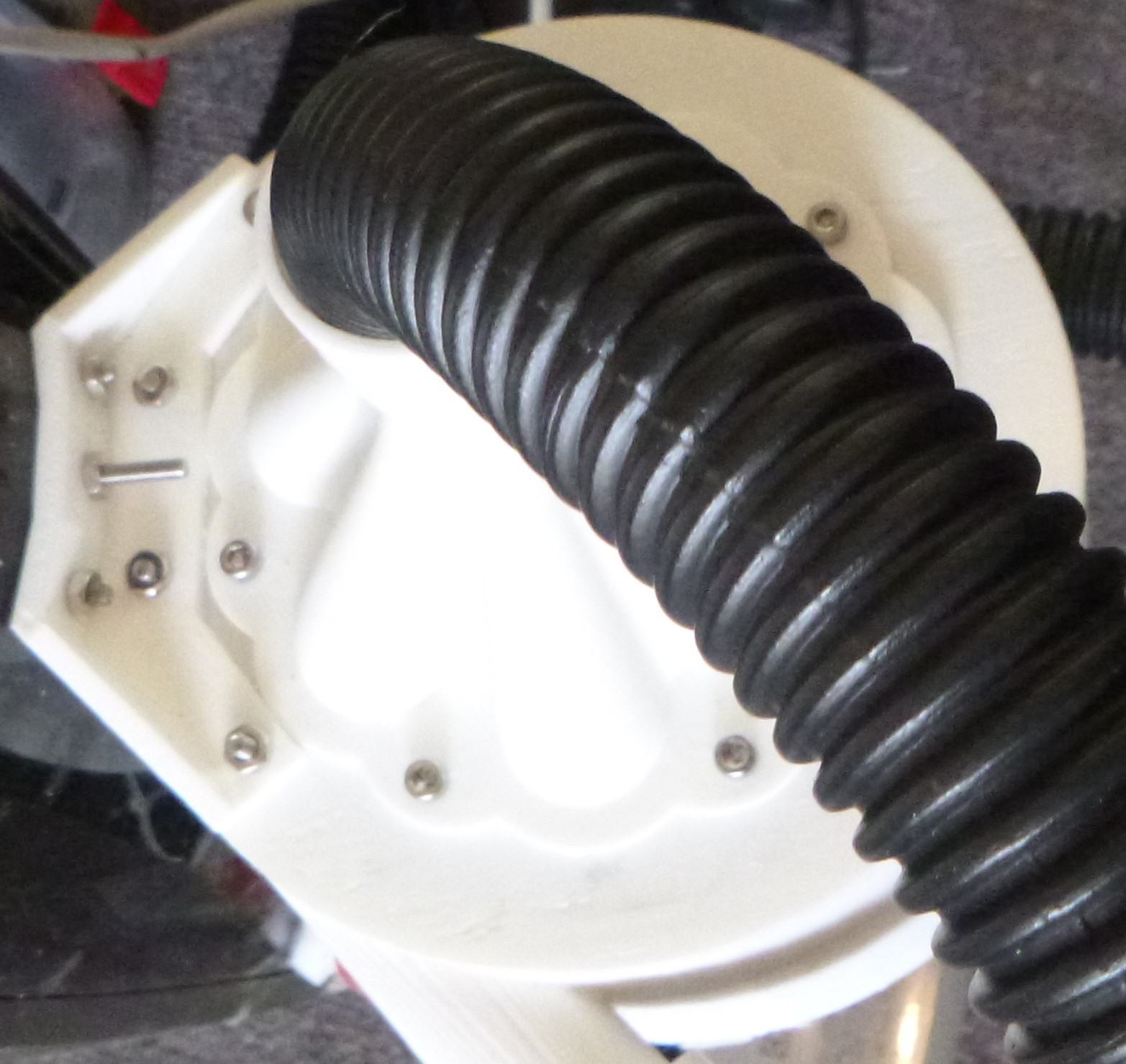
Mounting the extractor.
![]()
Using the same mounting points as the first attempt. A printed bracket was versioned to fit and then attach to the extractor by drilling four 3mm holes piloted by the bracket. The bracket was then bolted to the extractors chamber fine element chambers screwed on sealing the chamber and extractor mechanism. No gaskets or silicone seals used at this time.
Initial Assessment
![]()
![]()
Apparent success! The above images were taken after the first short run of this extractor. They show most of the debris in the main chamber and the small chambers, difficult to see, holding a small amount of fine dust.
Initially when the extractor and the original chamber was taken off the vacuums chassis there did not appear to have any additional detritus around the filter. This was unlike the first iteration were it was obvious that material had made it through the extractor. So this was a good sign. Continued dismantling of the debris accumulating chambers revealed that most of the material was contained within the first chamber.
Possible problem/s
The size of the plumbing is smaller than is desirable due the restricted volumes that is being worked with. This may be making the motor work a little harder than preffered, however putting is a fresh clean filter may address this. An old dirty filter would put more strain of the motor than small diameter hoses and this should not require changing for a long time.
Analysis
A quick calculation of the costs and possible benefits.
The vacuum itself was about $280AU and subsequent replacement filters $23AU, postage about $10AU.
The filters are supposed to be replaced every 6 months. So over a 4 year period that is $92 + $10 for postage.
The major reason this device was made was because the filter needed cleaning every time the vacuum was used. This took about 10mins and if vacuuming once a week over a year that is 8.7 hours @ $22/hr, calculated on housekeepers wage, that's $190 for a year. Now it takes a minimal time and is way less shit.
On the assumption that the vacuum runs more efficiently and extend the life of the vacuum by 50% the total value of the extractor is,
140 + 1.5(102 + 190 ) = $578 over a 6 year period.
-
CAD Design Ver 2.
11/20/2017 at 11:16 • 0 commentsAddressing the issues from the previous version.
- Separating of the of the debris collection and flow structures need to be more pronounced.
- Assembly need to be easier.
- Simpler design with lower part number without the need of solvent welding.
- Redesign for printing.
- Debris collection is easily accessible.
- Hoses need to be attached easier. (todo)
![]()
Separating the inlet stage and the cyclone stage the external shell forms the main chassis able to collect the larger particulates and hair, hair was a real problem. This also has been altered to make the assembly easier with all seven dust collectors serving the dual purpose of mechanical seal.
![]()
Assembly will be by screwing the collectors onto the base.
![]()
more
![]()
ok
![]()
The CAD will be released if the design works.
-
Version 1. Review
11/19/2017 at 04:29 • 0 commentsAfter running and trying the vacuum under different condition I developed an understanding of how this device does and doesn't work. Initially this device did seem to work to some extent, but this did not last long and alterations were make to address the issues. These alterations did not work at all and made the device not functional. However, it gave an insight into how such a cyclone vacuum system works.
Outlining the issues and why they are important to function.
The purpose of this project is to remove the fine particulate from the air before it gets to the supplied filter. Initially this was successful and the only debris that accumulated around the filter were the larger and lighter, eg. plant material. So the this gave the first result about the fluid flow structures and the causes of these structures.
![]()
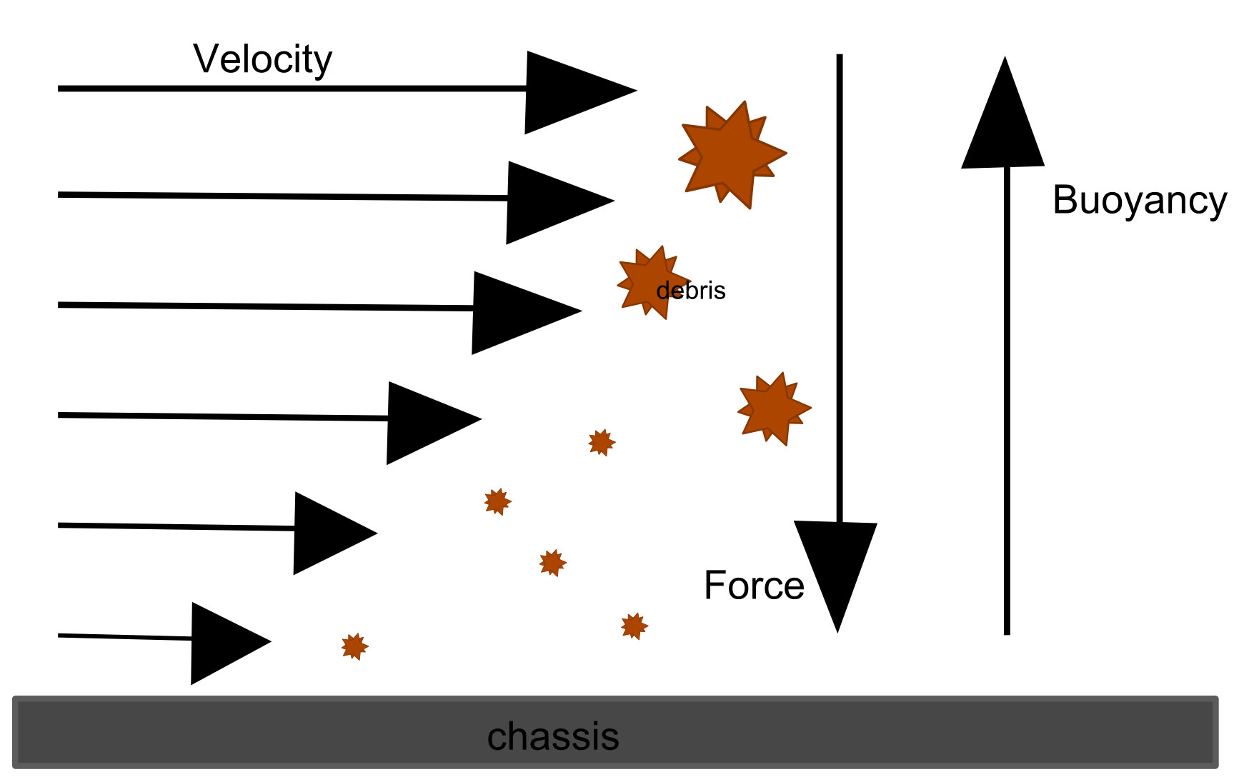
The basic illustration of the flow structures above forms the input and initial sorting mechanism. Here is where the main area of the design impacts how effective the sorting mechanism is. As the flow rotates about the centre the debris is forced against the exterior. However, inherent in 3D printing the surface is not smooth stalling the debris and reducing the force against the wall. My thinking is that this explains why the larger and lighter plant material does not deposits into the bottom of the system. This in turn clogs up the rest of the system slowly deteriorating its effectiveness. The image below attempts to illustrate the physics of the boundary conditions with forces.
![]()
To counter the clogging of the of the system a grate was placed across the entry of the main cyclone mechanism. This caused more problems than it solve. Air was then pulled into the cyclone exist therefore destroying the mechanisms function. This super poor decision at least reinforce the need and reasons for a redesign of the inlet and cyclone mechanism.
![]()
Improvements for Second version.
- Separating of the of the debris collection and flow structures need to be more pronounced.
- Assembly need to be easier.
- Simpler design with lower part number without the need of solvent welding.
- Redesign for printing.
- Debris collection is easily accessible.
- Hoses need to be attached easier.
-
The build.
04/25/2017 at 08:00 • 0 commentsWithout going into to many details about how I came to the dimensions because to logic was crude and was mostly governed by the size of the vac and flex hose available.
![]()
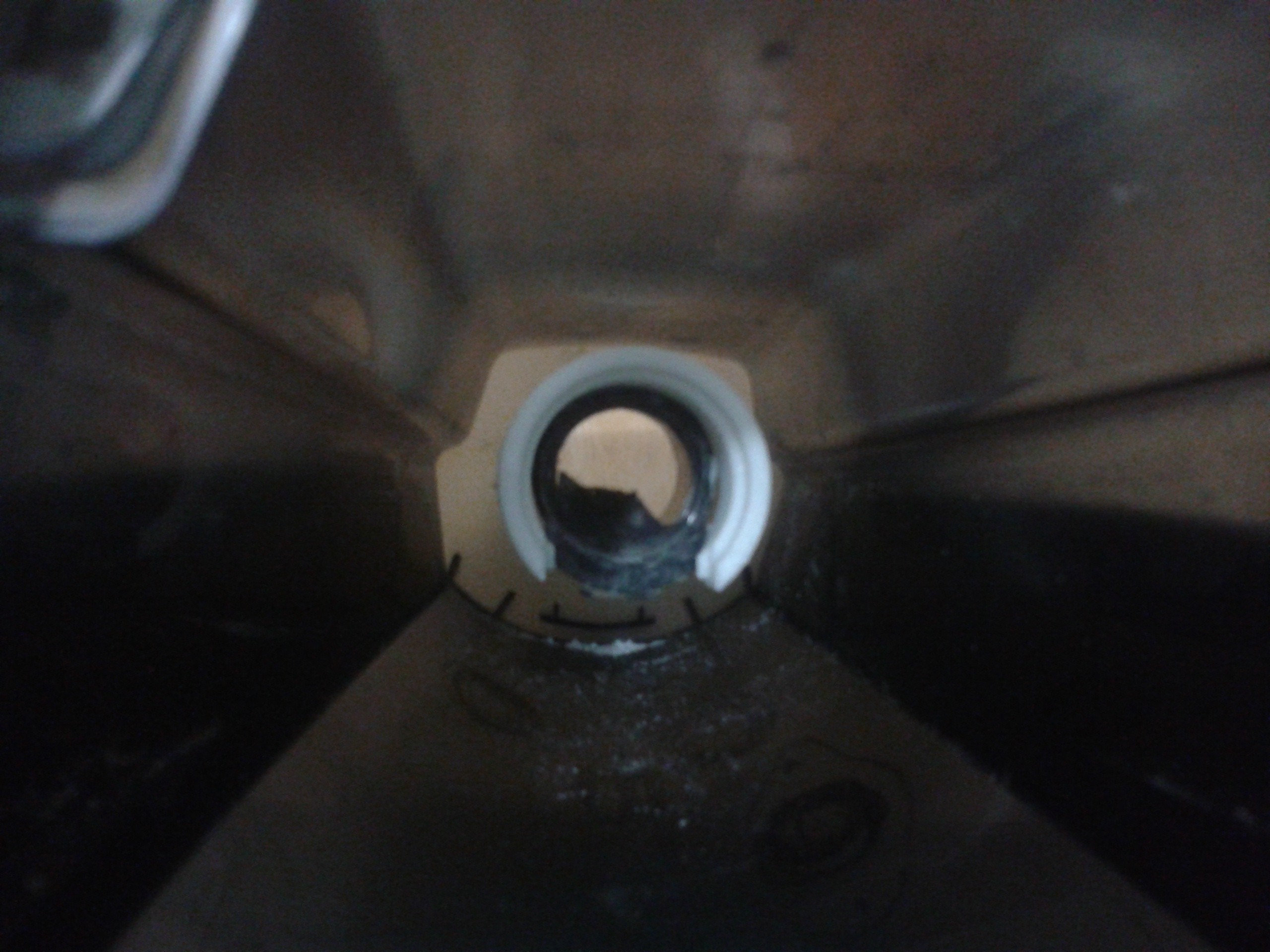
This give a rough guide as to size of the body, the hose was limited as the common flex vacuum hose was just a bit to big. Searching I came across so 22mm outdoor water hose, not ideal but it would work in the constraints of the vacuums camber. The image below shows the original idea of a bracket interfacing with the chamber inlet, but it also shows the space constraint.
![]()
The hose needs to sit there then turn and exit just where that dark circle is drawn because the filter that i was always planning to keep took the remaining volume. However, it turned out that the hose would fit inside the inlet perfectly creating a stable seat.
![]()
No going back from here the holes where drilled and filled, and the hose inserted.
![]()
Going back a few steps because I printed the extractor first, but these images illustrated some early design decisions as to how the space inside the chamber was a major influence. For example on of the original idea was to have the extractor contained within the chamber. The tightness of space and lack of ability to model parts exactly to the shape and dimensions of the chamber ruled this out.
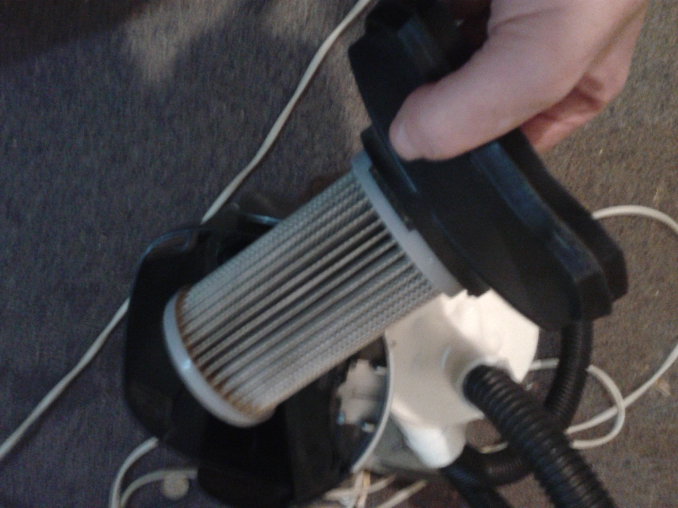
![]()
The filter and the chamber that it came from.
Design and CAD
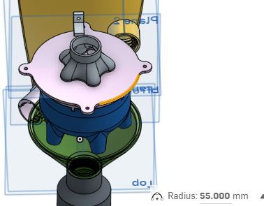
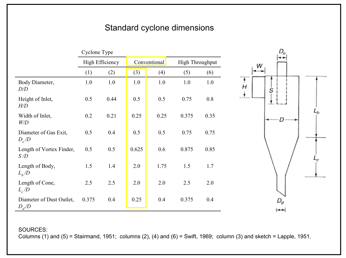
Knowing that the dust extractor is a common and relative old technology the design started from gaining knowledge of how this technology actually worked. Standard dimensions were easy to find and simulations consolidated some thinking about the lower portion of the cyclone.
![]()
The principles set the cyclone throwing the dust to the sides and it then falls below the cyclone to the chambers floor. But, having a single cyclone would require a larger chamber and from principles it would not have a high velocity air speed. So splitting the flow into originally 4 then 5 cyclones would substantially increase the angular velocity.
Printing the flow generator also provided design constraints but also opportunities with an organic structure separating the incoming air and the high velocity cyclones. From here however it is not clear if this provides a solution but this is what I printed. So fingers crossed.
![]()
bottom half
![]()
top half
![]()
and together
![]()
All the parts printed.
![]()
The upper and lower cyclone generator solvent welded together.
![]()
A threaded attachment was printed separately and stuck to the chambers inlet with the help of silicone.
![]()
![]()
similarly the outlet
![]()
Inlet to the vacuums chamber.
![]()
And the final result with brackets printed, solvent welded, drilled and screwed.
![]()
It does work.......
Dust Extractor
A 3D printed cyclonic dust extraction attachment for a domestic vacuum cleaner.