Close
0%
0%

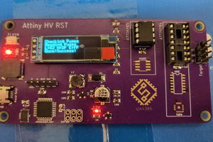
Power Supply B3603 Alternative Firmware

B3606 is a cheap MCU controlled power supply, I'm reverse engineering it and writing software to add serial port and more features.

Similar projects worth following
The B3603 is a cheap power supply that is available from Aliexpress for as low as $11.50, it features an STM8S003F3 microcontroller and has a fairly good accuracy. It has a physical serial port connection but the software doesn't implement it apparently. The buttons share the TX/RX lines as well which will complicate things a bit but I really want a computer controllable power supply to experiment with low voltage behaviors and automating the testing of battery operated devices.

This project is about reverse engineering the device and writing an alternative firmware for it, it might also be possible to create an alternative top-board and people have connected the bottom board to an Arduino for control but I wanted something that will only require a relatively simple software change to unlock many more features. The only extra hardware cost would be an STLinkV2 programmer that can be had for $3.5 on AE as well and some minimal sodlering.
  • 1 × B3603 power supply A ready made unit for which we will modify the software
  • 1 × 2.54" female header (need 8 pins) Connect the SWIM header for programming and the serial header for communication
  • 1 × USB to TTL serial adapter Can be an Arduino (Pro mini f.ex.) or a CP2102 device

  • Calibration working

    Baruch Even03/18/2015 at 18:42 0 comments

    I decided that the flash size is not sufficient to allow internal calibration logic and now resorted to external calibration with a script and a sigrok-enabled multimeter. This allows for very accurace Least Squares Estimation and gets the accuracy to be pretty much spot on.

    I'm happy with the project as is even though I can see many improvements that are possible to it but for now it is sufficient for my needs and I have other projects to attend to so I don't think I'll work on it so much from now on.

    I'll still appreciate comments and especially patches or merge requests if someone fancies to work on this further.

  • PWM Accuracy Improved

    Baruch Even03/02/2015 at 18:40 0 comments

    I figured a way to get the full 13 bit resolution of the PWM and now I get the full value range. I figured that my timer counter being 8192 is just a shift of 13 so I can avoid overflow by not shifting up 13 and down 10 but rather just do the entire calculation with an additional shift of 3.

    The ADC on the face of it is a lost cause, it is only 10bit accuracy so I only get a change every 8 values of the PWM. I need to look at ADC averaging, I started to think about it and wonder if it's worth spending time to do it. I currently take a snapshot of the ADC and need to average it out anyway but originally wasn't planning to use fractions in that average.

    I did some code size reductions and the code is now at 7860 bytes. It was at 8100 beforehand and got down to 7600 and then the new PWM accuracy took more space. I kinda like the serial text interface but not sure how long I can hold on to it in its current verbose state.

  • Calibration of measurements

    Baruch Even02/28/2015 at 20:32 0 comments

    I've started to work on the calibration feature. It is shaping up nicely and improves somewhat the accuracy of the measurements but I'm still not getting to the level of accuracy that the original unit boasted (i.e. 0.01V and 0.001A).

    The unit is however already usable as is, the alternative firmware can receive commands by serial and exhibit good control of the device that makes it possible to use it just fine.

    The buttons still do not work and I don't do a great job with the display for now but these are features for interactive work and my main goal is the serial control anyway.

  • Small Improvements

    Baruch Even02/25/2015 at 21:48 0 comments

    Today I worked on improving the code and adding small but important (to me) features.

    The first is automatic and manual commit of settings. It is now possible to tell the device not to auto-commit and then be able to change both voltage and current in a single motion by setting the voltage, then the current and then commiting both into action.

    A configuration of the device options is now done automatically so it will be easier to deploy the firmware. This is an option that is required to be able to PWM control the voltage and current and it took me a while to figure out how to program the flash.

    The last feature of today is saving the configuration to flash for persistency. This is a small feature by itself but important to make calibration of the device worthwhile since otherwise it would be needed to calibrate it every time it is started.

    Along the way I improved the code to make it more manageable.

    Next up, calibration of the device.

  • Basic functionality working

    Baruch Even02/24/2015 at 05:29 0 comments

    It works!

    I can now set the voltage and current through the serial and it actually sets the output to the right value (haven't validated current limit yet).

    I needed to do proper calculation of the PWM values and for that there was a roadblock with integer overflows in the fixed point calculations. The initial setup for the current and voltage control was reversed.

    I also had a roadblock where out of the two units I have both have some issue now with the top board, one doesn't display properly and the other can't control the output properly.

  • Current state of things

    Baruch Even02/22/2015 at 21:56 0 comments

    • I do not control the Output Enable pin, but it doesn't seem to matter. No idea how it comes. It is always at 0V no matter what I do on the pin.
    • I can control the 7-segment display and it shows data consistently and nicely
    • I can control the CV/CC led, still didn't get to test CC condition to be sure of the full loop
    • I can measure with pretty good accuracy the Vin, Vout and Iout based on the theoretical numbers. I didn't attempt to calibrate my own unit yet.
    • I can control the PWM for the voltage and the current, this is not at all calibrate so the random I use and the output are off by a factor or so but it seem to work and only needs tuning

    This is now pretty close to being a minimally functional serially controlled power supply.

  • Fixed point parsing fixed

    Baruch Even02/22/2015 at 18:11 0 comments

    The fixed point parsing was incorrect due to an overflow, I had to set the variable to uin32_t to get it to work properly. I also needed to fix a rounding error that made the numbers off by just a little bit. Now it works very well.

    Now I need to work on the PWM calculation it is way off and makes no sense right now. Once I have the PWM working I will have essentially a working power supply that is serially controlled.

    I still don't know how to read the buttons in their weird setup. But that will wait a bit more. Once I get the PWM working I'll work on getting the display properly sorted to display the different values.

  • 7-Segment Display Works

    Baruch Even02/21/2015 at 22:08 0 comments

    I got the 7-segment display to work today, it lights up nicely and I have the bit patterns for all 10 digits done. It took some play to figure out how exactly to drive it even with the schematics that were reverse engineered by flex.

    To fit the code I needed to also get rid of the floating point so I worked to convert all such operations to fixed point arithmetic and it saved me some 3KB of space.

    Still need to work on the output power parts, I have an problem driving the output enable pin properly. Still not sure what I'm doing wrong.

  • Board Schematics

    Baruch Even02/20/2015 at 12:49 0 comments

    Board schematics for the B3606 top and bottom boards were done by user flex on the EEVblog forum. This should help immensely with figuring how to drive all the components.

    I've already managed to drive the CV/CC leds, partially successful with the 7-segment display. Still unsuccessful with the output enable part and the buttons.

    I did manage to get the PWM sorted but without the output enable it doesn't help.

  • PWM working, Unit does not

    Baruch Even02/18/2015 at 18:52 0 comments

    I got the PWM code to start working, at least when viewed in a logic analyzer. When I tried to put the top board on the bottom board and see if it works nothing comes out. The output pin is toggled, the PWMs are running but no output comes from the device.

    This may be also due to me wiring it once in reverse (the top board was upside down) so I may have destroyed it somehow. I'll try to debug this tomorrow with another unit that I have and see if and which part is damaged.

View all 11 project logs

  • 1
    Step 1

    Solder a four pin female header to the connect at the bottom of the top board

  • 2
    Step 2

    Connect the STLink V2 device to the header

  • 3
    Step 3

    Use the windows STVP programmer, verify it is read-out-protected, if not, please save the flash and eeprom

View all 7 instructions

Enjoy this project?

Share

Discussions

Luca Buccolini wrote 09/11/2017 at 21:52 point

Thank you for sharing your work Baruch!

Probably I missing something but I cannot find how can I change the working mode (CC vs CV) . It seems the PSU is able to work only in CV mode. Furthermore I notice a difference of about 0.5-0.7 V between the set voltage and the effective voltage (the unit is not calibrated but it seems the difference is a voltage drop of some diode).

  Are you sure? yes | no

Luca Buccolini wrote 09/12/2017 at 15:25 point

I've just calibrated the PSU and the output voltage is exactly the voltage that has been set. Good work ;)

Now I understand also that the CC/CV mode is set by the most restrictive value between Voltage and Current.

Despite the excellent regulation on voltage output, the current regulations seems very poor also after the calibration. I set a Vout=10V, Iout=0.3A on a resistance of 10ohm. I read a voltage of 1.73V thus I've an effective current of 0.173 A. The led of CC mode is ON but the current is very different from the desirerd current.

Have you notice this behaviour?

  Are you sure? yes | no

Baruch Even wrote 09/19/2017 at 18:36 point

I have to admit I didn't test all the options and all values. You can try to measure what is actually the current and see if the measurement is correct. Did you also calibrate the current measurement?

  Are you sure? yes | no

Baruch Even wrote 09/19/2017 at 18:37 point

The defaults were given from my unit and I presume that each unit will have its own differences so you really have to calibrate it for your own device. I see below that you did that and it works in the voltage control.

  Are you sure? yes | no

Elliot Williams wrote 05/26/2017 at 07:33 point

Just swinging by to say thanks -- I needed to get PWM working on a totally different STM8S device, and your code was super helpful.  I was actually making other mistakes in the process -- really dumb, don't ask -- but having some working code to play around with made debugging a lot easier.

The whole AFR0 song and dance is lousy.

  Are you sure? yes | no

Baruch Even wrote 05/26/2017 at 15:13 point

Cool!

It's great to know my code is helping others in their quests. It wasn't easy to figure things out on the STM8, there is very little code out there for one to learn from.

  Are you sure? yes | no

Pete Dixon wrote 10/29/2016 at 11:49 point

I'd like to thank you for sharing this project.  I needed a cheap serial controlled variable power supply, and this looks like a good solution.  I am having trouble finding the AOF0 flag that you have listed in step 6 of your instructions.  Is the AFR0 flag an equivalent?  It's second option is listed as 'Port C5 Alternate Function = TIM2_CH1, Port C6 Alternate Function = TIM1_CH1, Port C7 Alternate Function = TIM1_CH2'.

  Are you sure? yes | no

Baruch Even wrote 06/12/2016 at 17:14 point

The serial is indeed 3.3v

  Are you sure? yes | no

[deleted]

[this comment has been deleted]

Baruch Even wrote 06/12/2016 at 06:43 point

Yes indeed. The display and buttons are parts I never finished. The device is pretty brittle and touching it at the wrong place at the wrong time can damage the display as I did on at least two units which is part of why I gave up on the display and just used the serial interface.

  Are you sure? yes | no

transmissions4less wrote 04/09/2015 at 07:45 point

I got the oem st-link programmer st/8 and st/32 usb one and tried to flash the mcu with i get a message that the device is write protected, does it mean i shall get new mcu? regards

Error : < PROGRAM MEMORY programming failed.
Error : < Operation aborted.
> Reading section [8000-9FFF] of  PROGRAM MEMORY area...
Cut Version and Revision of device: 1.2
Error : The device is protected
Operation aborted
Error : < PROGRAM MEMORY reading failed.
> Programming  PROGRAM MEMORY area...
Cut Version and Revision of device: 1.2
Error : The device is protected
Operation aborted
Error : < PROGRAM MEMORY programming failed.
Error : < Operation aborted. 

salim

  Are you sure? yes | no

Baruch Even wrote 04/09/2015 at 07:56 point

The device is protected when coming from the factory, that's why I couldn't also read the original firmware to see what it does.

It is however possible to erase the protection and reflash the device with my firmware and there is no need to replace the chip itself. I didn't try it yet with the open source tools but the windows programmer from STM can remove the protection, it will also erase all the flash as part of that so you'll need to program my firmware on top for it to work.

Let me know how it goes for you.

  Are you sure? yes | no

transmissions4less wrote 04/10/2015 at 08:48 point

today i got new ST8  mcu and  soldered it to the the board, and tried to flash it with the compiled firmware with sdcc and somehow it seems it does not work ( i just get a counter from 0 to 9 and then 9 to 0,  will you upload the latest firmware of ihx file to github  so I can try again to see why i am having this problem. also can u explain in deatils how to set the byte options as seen on stvp, thanks

  Are you sure? yes | no

Baruch Even wrote 04/10/2015 at 08:59 point

There are many variations for the STM8 chips, the one the code is made for is the same one as the original which is an STM8S003F3, each chip has different pinouts and are not necessarily compatible for in-place replacement.

The latest version is already on github, the direct link is https://github.com/baruch/b3603/releases/download/v1.0.1/b3603.ihx

It displays on the screen the input voltage since I don't have anymore a unit with a working screen I didn't work on the display part much.

For the STVP programming you need to go to the options page and just change the flash readout protection bit to false, and download the options to the device. It will allow programming after that for the firmware.

  Are you sure? yes | no

transmissions4less wrote 04/10/2015 at 20:16 point

I complied your new code without errors but still converting the units to a counter from 0  to 9,  the first time i complied your code about 20 days yes it seems working but without buttons, maybe you need to revise the code and check what is causing this problem. anyway I will just port it to arduino till this isssue gets resolved.

thanks

salim

below is what i see in stvp 

PROJECT:

FileName: pp.stp


CONFIGURATION:
Hardware: ST-LINK
Programming mode: SWIM
Device name: STM8S003F3
Port: USB


PROGRAM MEMORY status:
[0x008000 - 0x009FFF]
File: b3603.ihx Checksum: 0xB0C0A
Programmed
Memory checksum: 0xB0C0A


DATA MEMORY status:
[0x004000 - 0x00407F]
No File
Not programmed
Memory checksum: 0x0


OPTION BYTE status: *
No File
Programmed
Option byte 0: 00
Option byte 1: 00
Option byte 2: 01
Option byte 3: 00
Option byte 4: 00
Option byte 5: 00
Memory checksum: 0x1

Cut Version and Revision of device: 1.2
< OPTION BYTE programming completed.
< PROGRAM MEMORY programming completed.

  Are you sure? yes | no

Baruch Even wrote 04/10/2015 at 20:20 point

The buttons do not work in my code yet since I didn't figure out how to read them properly.

The settings you show from STVP seems correct to me.

  Are you sure? yes | no

transmissions4less wrote 04/11/2015 at 01:53 point

ok I found a code dated march 18 from github, i compiled it and yes it seems working without buttons, it seems the problem only exists on the updated code you made lately.,  the one that works is  b3603.ihx witth the 19k one.  I am using arduino serial terminal with 38400 baud rate and it works just fine, I really loved your work man.

STATUS:
OUTPUT: OFF
VOLTAGE IN: 15.35
VOLTAGE OUT: .66
CURRENT OUT: .246
CONSTANT: VOLTAGE
MODEL: B3606
VERSION: 0.1

OUTPUT: ON
PWM VOLTAGE 1154

PWM CURRENT 2281

  Are you sure? yes | no

transmissions4less wrote 03/18/2015 at 17:22 point

Hi Baruch,, 1st thank you for your good spirit and great work, i've just complied your code with sdcc  under Windows7 and got a hex file size of 23k,  am i missing something ?. 

regards

salim safran

  Are you sure? yes | no

Baruch Even wrote 03/18/2015 at 18:50 point

I'm using the very latest sdcc out of subversion to build it properly, it gets the code tightly down to about 7KB. I've pushed the built hex file into the repositor as b3603.ihx, you can use that to simplify the process.

  Are you sure? yes | no

transmissions4less wrote 03/19/2015 at 01:10 point

Thank you very much, can u please provide the links to the sdcc you used or was under Lunix, also do have c or c++ code instead of python to see how to integrate it with Arduino,  I am  interested in i2c interface so i can use it with raspberry pi, any ideas?,

i just checked theb3603.ihx  file and it is 16.978 kb and when i convert it to hex it gets to 20K , how can i use that to load it to the mcu with only 8kb?.

please advise

 wish you the best.

  Are you sure? yes | no

Baruch Even wrote 03/19/2015 at 08:27 point

The code of the firmware is in C so if you want to port it to Arduino you can do that but obviously it is littered with STM8S specific code. The Python code is only running on the host to do calibration and some testing.

The RPi also has serial port so you can use direct serial instead of i2c, I never did an i2c target to know how well it can work so I can't advise you there.

The ihx file is text based so is much larger than the actual data, you can use makebin utility to convert it to binary and see the actual size of it. My makefile shows the code size from the map file that is generated during the sdcc build.

My sdcc build is on Linux so I don't think it will help you much.

  Are you sure? yes | no

transmissions4less wrote 03/19/2015 at 15:30 point

I used makebin before but it gave errors of buffer limitations, it seems it is a bug even though i got the latest download on their web. i used hex2bin  from http://hex2bin.sourceforge.net/ and did work and gave me 7k bin file as you mentioned.  again thank you for this great work sure it will help a lot.

  Are you sure? yes | no

Baruch Even wrote 03/19/2015 at 19:58 point

Looks like makebin generates a file with the data in the offset specified and for the STM8S the code starts from 0x8000 so the file size is not a good indicator as it starts with all zeroes.

The STVP programmer takes the ihx file directly for programming so that wasn't a concern for me, I just fed it the ihx file and everything worked.

  Are you sure? yes | no

Baruch Even wrote 02/17/2015 at 20:00 point

Right now I'm only on the verge of figuring out PWM properly on the STM8S003 and only then I'll be able to know what I can get. I already can read the voltage input and believe that voltage and current output will work as well once I actually start to do the PWM control.

I believe the control board is the same on both units so the same code should be able to work on the B3008 as well, there is also a similar B3606 and a step-up converter that uses the same control board. Some other people have chimed in that have them and might be willing to test once I have something that works.

  Are you sure? yes | no

Jakob Hoppermann wrote 02/17/2015 at 23:55 point

Good progress, seems we're about equal on this. I will of course help as much as I can too. I have ordered most of the converters in this series, to test them out and hopefully provide the results for the DIY-community. 
On the BST400 (boost-converter) the control board is labeled "2P524A". Needless to say Google gives no useable results. The control board on the B3008 is unlabeled but exactly the same. They work in both units and of course the voltage/amperage-data is saved in the control unit itself and follows it on the different units.

  Are you sure? yes | no

Baruch Even wrote 03/19/2015 at 08:28 point

The code is working now and does fairly well, I'd be interested in seeing what works and what doesn't on the other related boards.

  Are you sure? yes | no

Jakob Hoppermann wrote 02/17/2015 at 17:10 point

Hi Baruch,
I've been working on the same thing, but for the B3008. It has pretty reasonable serial-implementation, so I'm able to adjust the voltage and current with an external MCU, as well as getting readings from the unit. What are you able to get out of yours?

  Are you sure? yes | no

Similar Projects

Does this project spark your interest?

Become a member to follow this project and never miss any updates