jay-t
jay-t-
Bluetooth module RN-42
10/11/2015 at 14:17 • 0 commentsI plugged a bluetooth module into my mouse bot. It is connected to the Propeller TX/RX serial pins.
From my mobile phone app I can now control the robot. The Tachyon Forth gets the commands in direct mode. I only flashed Tachyon and the EXTENDS.FTH Forth extension into the EEPROM. The control Forth program will be transfered over bluetooth into the Propeller RAM on a click onto the "PROGRAM" button. Then the robot is ready to listen to commands.
This way of programming is more flexible then flash into the EEPROM. I can test new programs very easy this way.
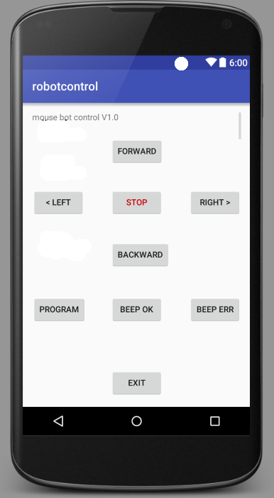
The mobile phone app is written in Java with Android Studio. I just had to find a good bluetooth example. Then I changed things to my needs. The response message of the Tachyon Forth is shown below the control buttons. So I can see what is going on. Here is a picture of the GUI:
![]()
-
IR remote control prototype
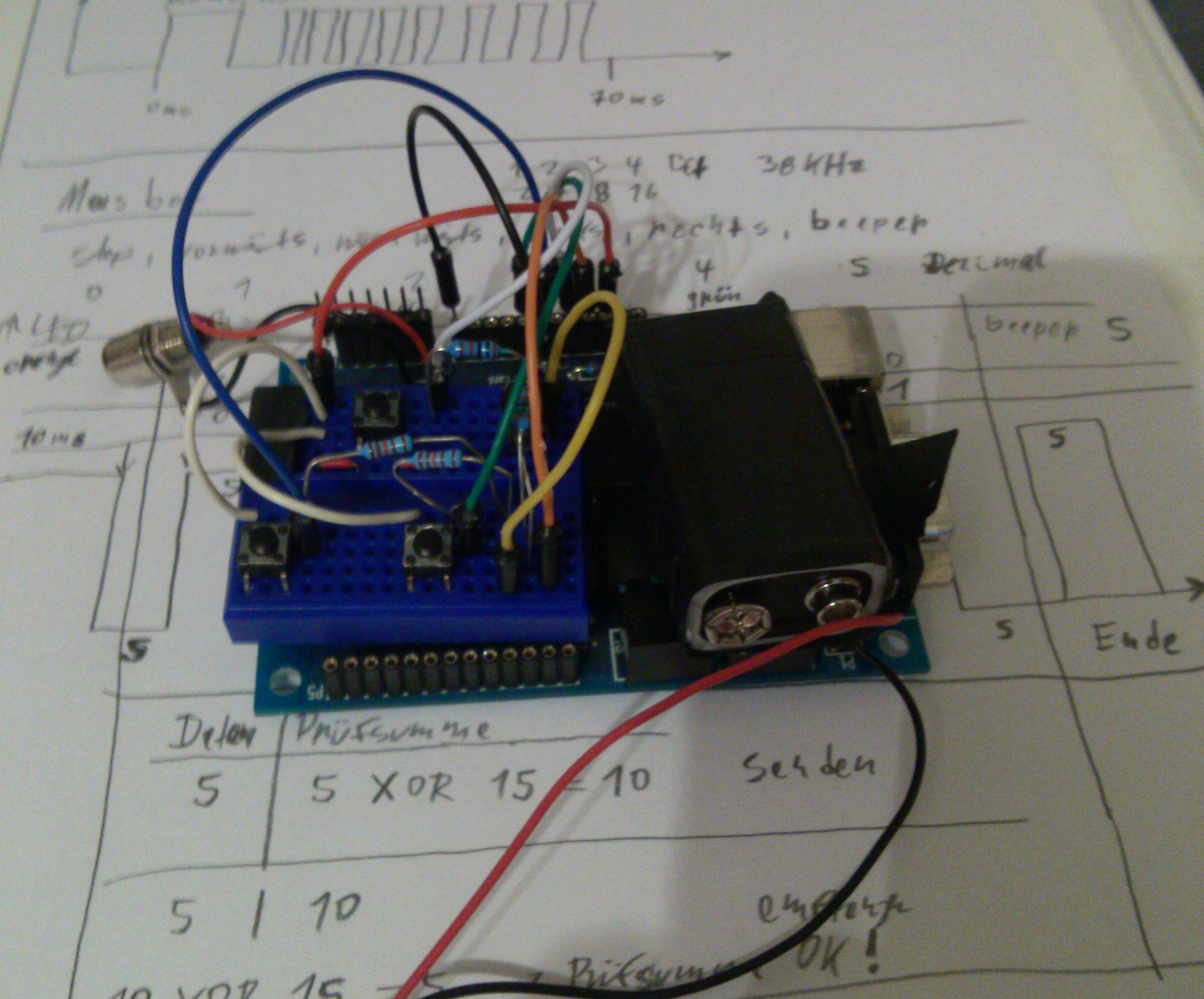
02/23/2015 at 21:15 • 0 commentsI made a IR remote control prototype with my Propeller One board and a tiny bread board. The three push buttons are for "forward", "turn left" and "turn right". After the startup beep sequence the bot waits for the user choice:
"Turn left" pressed starts the automatic drive mode and the bot searches light.
"Turn right" pressed starts the user manual IR control mode. So both is possible after switching on the mouse bot. Now I want to solder this onto prototype perf board. The IR control also will get a "backwards" button. And some other buttons for "special" commands like "beeeping".
![]()
-
IR signal received
02/06/2015 at 16:26 • 0 commentsI made a successful IR signal transmit to the mouse bot. My protocol sends 4 bits now and the receiver program works.
For a one it sends a long on and a short off pulse. For a zero it reverses it with a short on and a long off pulse. Behind the data bit follows a stop mark. The timing of the signal was important. The receiving program measures the on and off pulses. If the on pulse was longer as the off pulse then it's a one bit. The real time of the pulse length is not measured. Only the relative timing is important.
I did take care to make the signal decoder loops stop counting if a threshold value is reached. So the decoding won't wait forever for a signal change if a "false" signal was received.
-
IR signal transmitting test
02/02/2015 at 21:24 • 0 commentsI connected a IR LED on a little breadboard with my Propeller One board. And did try some signal sending to my mouse bot. It's a 4 bit signal sent.
The signal receiving on the mouse bot didn't work right. I use counter loops to "measure" the duration of the IR pulses. A one is send as a 2 ms on and a 1 ms off pulse. And a zero as a 1 ms on and a 1 ms off pulse.
Now I'm working on the decoder to get the signal right. I have to take care of not make the decoder loop endless waiting for a signal change which never comes. So I have to add a counter break if some high value is reached.
The goal is to build a remote control for the mouse bot. Or at least try that.
-
Schematics & firmware released
01/14/2015 at 18:45 • 0 commentsThe schematics and firmware are released now on my blog. The schematics are in PDF and in KiCad project file format. The firmware includes all the needed Tachyon files and my Tachyon Forth files for Jimmy the mouse bot.
The firmware lets mousey seek and drive for the brighter light side. This is funny to play with.
Here is the blog entry: Jimmy the mouse bot
Have some fun with this.
-
Load firmware from SD card
01/11/2015 at 13:42 • 0 commentsI'm using now a nice Tachyon feature, it's the ?AUTOLOAD command. It checks the SD card for an updated FIRMWARE.ROM file. If it finds one then the new firmware is loaded into the EEPROM and it reboots then.
To use this I had to first program the EEPROM with the Tachyon Spin program. The next step ist to prepare the SD card with two files:
FIRMWARE.ROM, with a size of 32 KB (or your EEPROM size), filled with SPACES (ASCII code 32).
WORDS.DCT, with a size of 4 MB (should be enough), filled with SPACES too.
The files must be with filled with SPACES because the EASYFILE functions can't create files. So we have to take care of this. The WORDS.DCT file will store Forth words later. So it can store program parts and make more free RAM possible.
I put the SD card in my module on my Propeller board.
Then I loaded EXTEND.FTH, SDCARD.FTH, EASYFILE.FTH and SDWORDS.FTH over serial connection with a terminal program.
The next step was to run COMPACT, to move Forth words to the WORDS.DCT dictionary file. Then I loaded my firmware files.
The trick is to put the command ?AUTOLOAD as the first command into the word which runs as the AUTOSTART word. Now I can simply create a new firmware ROM file on my Propeller board and copy it to the SD card. And don't have to open Jimmy all the time to get access to the EEPROM.
-
Follow the light
01/10/2015 at 15:45 • 0 commentsI wrote a Tachyon Forth program which lets Jimmy sense light and move to the brighter side. It reads out the light sensors value and rotates Jimmy to the brighter side.
With the IR sensors Jimmy avoids obstacles while following light.
-
Gear motors mounted
10/19/2014 at 12:29 • 0 commentsFinally I mounted the two gear motors and wheels. Mousey now can drive.
I wrote a little control program in Tachyon Forth, so Mousey uses it's IR sensors to avoid obstacles. This is just the first step to improve the program further.
-
Motor driver rebuild
08/19/2014 at 09:00 • 0 commentsNow I found out that the pins of a Propeller are to weak to switch an IRL 510. It seems that my Propeller died after switching the motors on. I now want to use a L298 dual H bridge motor driver from Solarbotics. It's sold as a kit. Then mousey II can drive forward and backward at different speeds.
-
New motor driver tested
08/17/2014 at 20:31 • 1 commentI soldered a new motor driver with an IRL 510 mosfet. I did this because the transistors I used got too hot and burned out. The driver for the left motor works with the old motor. So I can now build the driver for the right motor in the same way. The mosfets don't fit inside the mouse case, so I made a new tiny board which will be placed on top of the SD card module. This isn't pretty but will work. Also the board has connector pins soldered in for more easy handling of the cables that are connected to it. This looks more professional as my direct wired boards before.
Jimmy the mouse bot
I'm building a mouse bot based on the Parallax Propeller microcontroller.