0%
0%
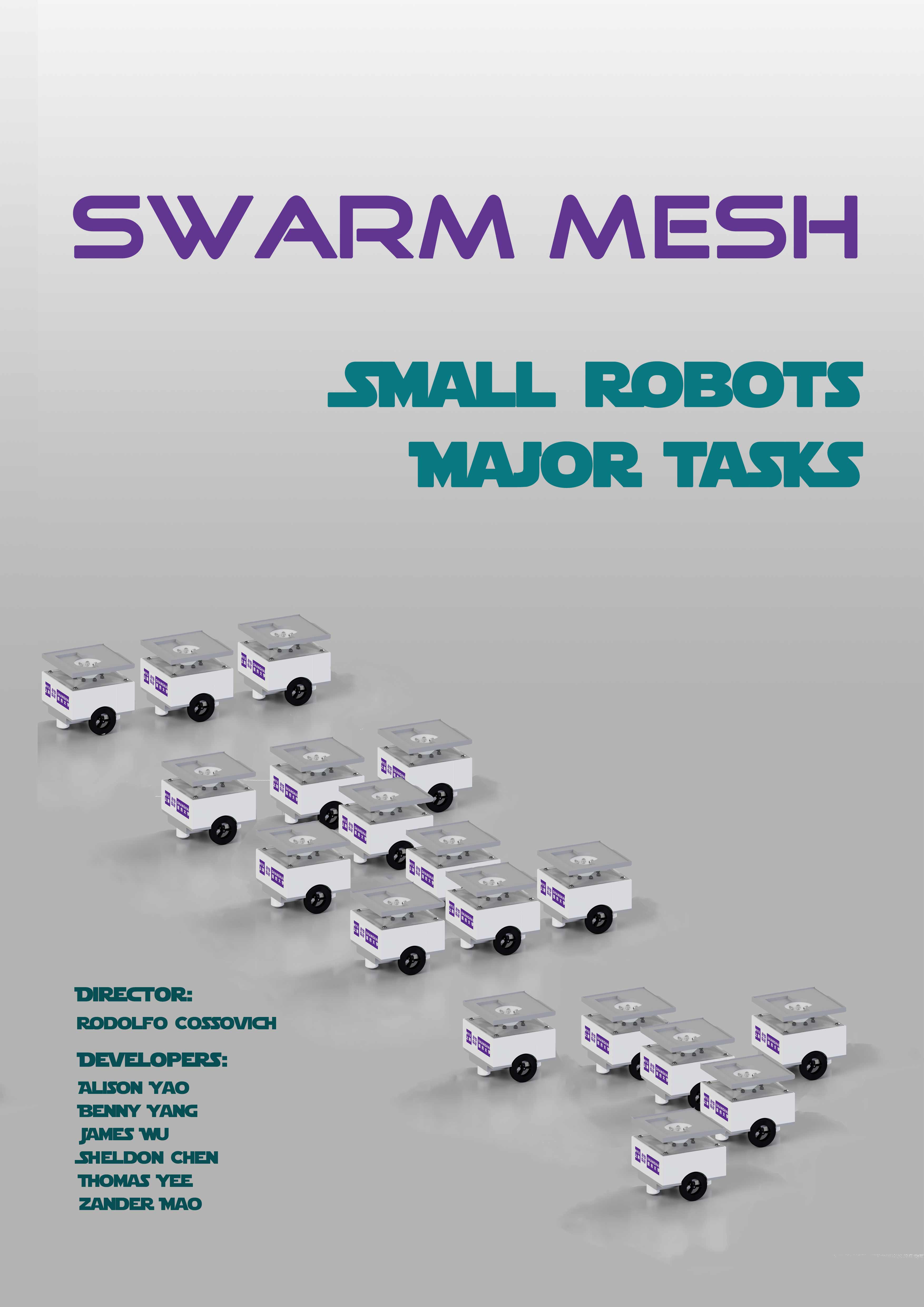
Swarmesh NYU Shanghai
Scalable swarm robot platform using ESP32 MESH capabilities and custom IR location
 Rodolfo
Become a Hackaday.io member
Already have an account? Log in.
Just one more thing
To make the experience fit your profile, pick a username and tell us what interests you.
Pick an awesome username
hackaday.io/
Your profile's URL: hackaday.io/username. Max 25 alphanumeric characters.
Pick a few interests
Projects that share your interests
People that share your interests
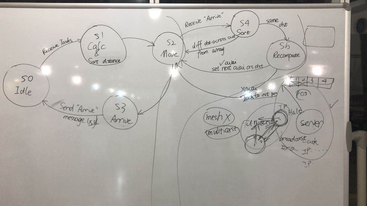
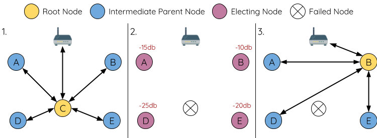
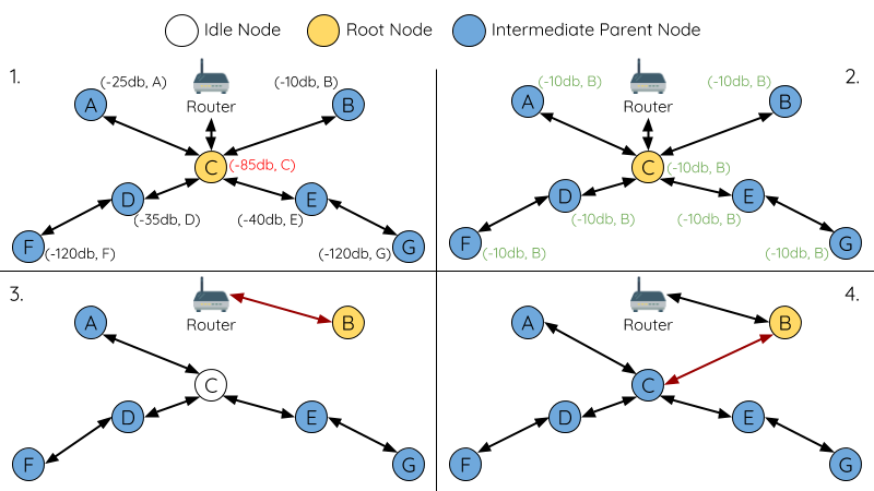
 Figure 1. FLow chart of task assignment


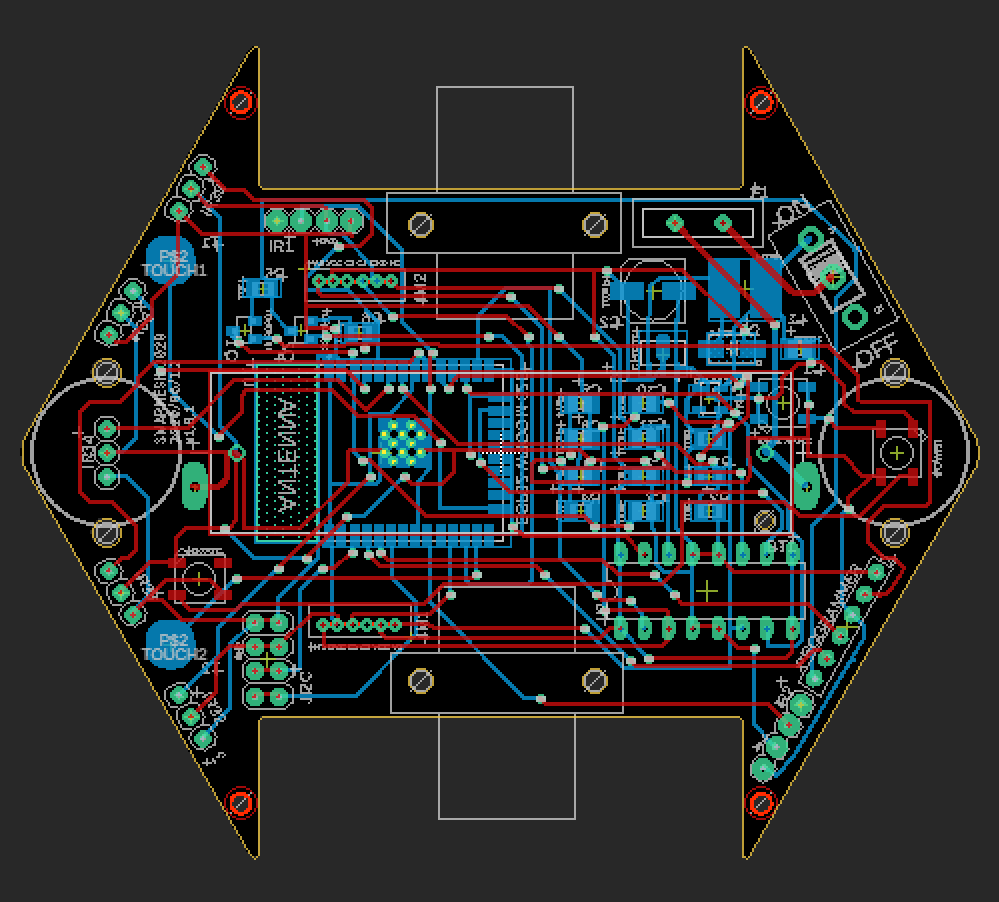
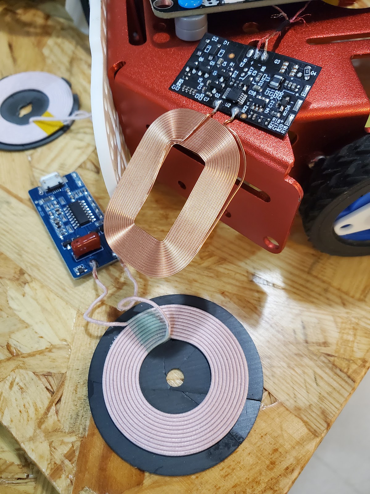
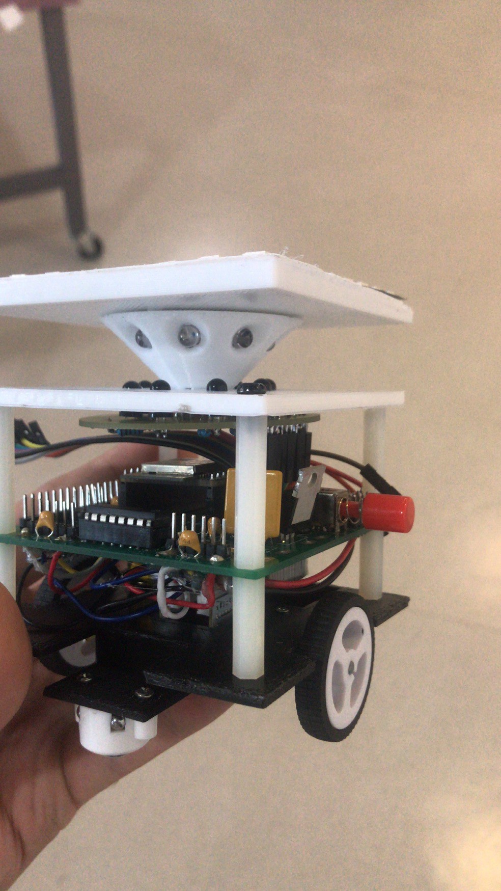
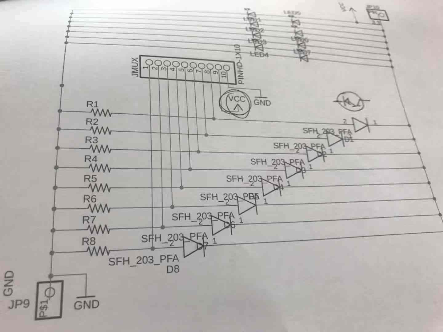
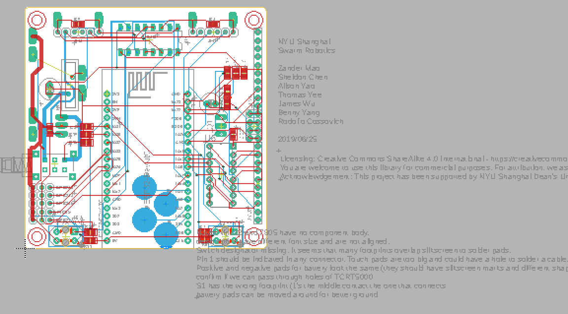
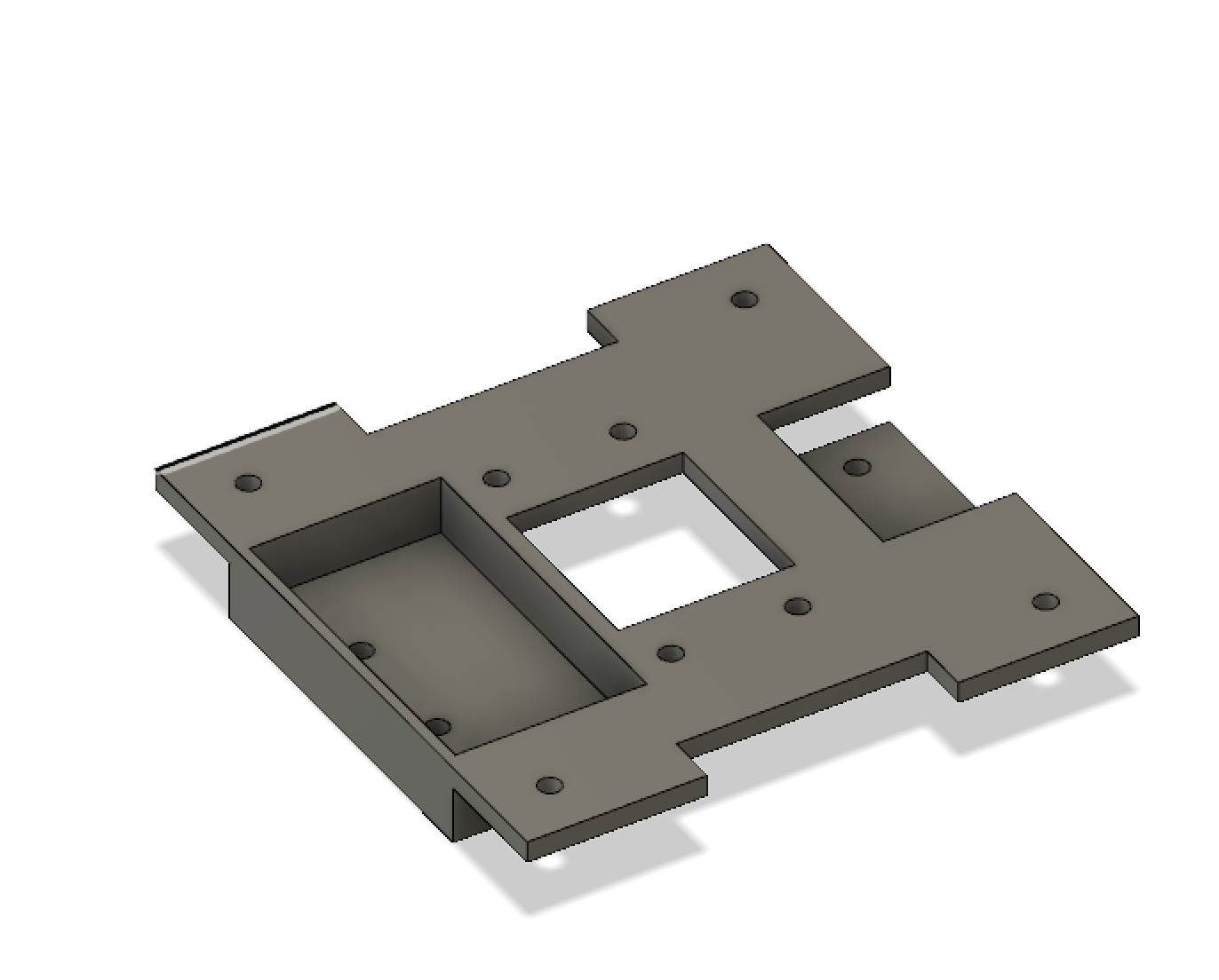
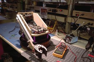
 Figure 3. Receiver plate design
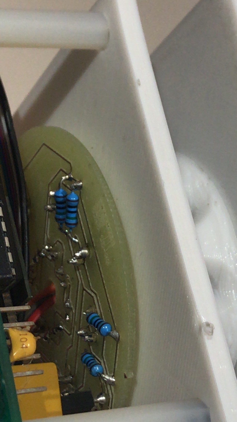
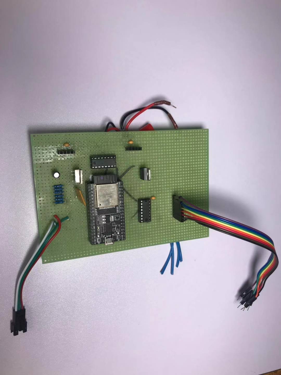
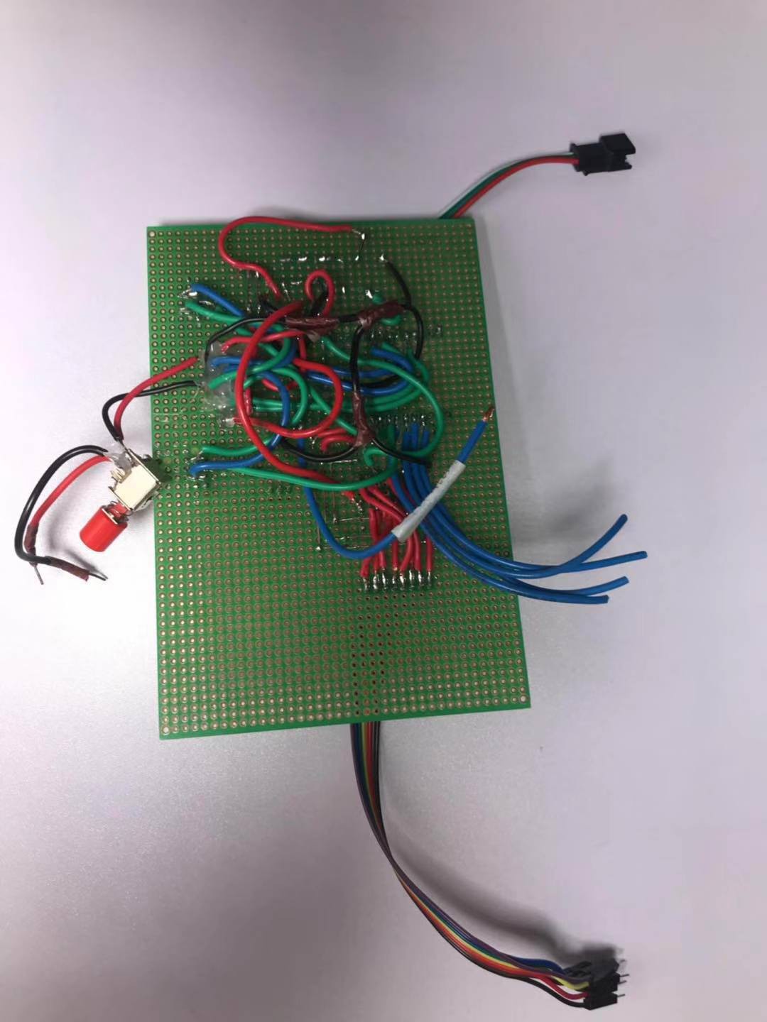
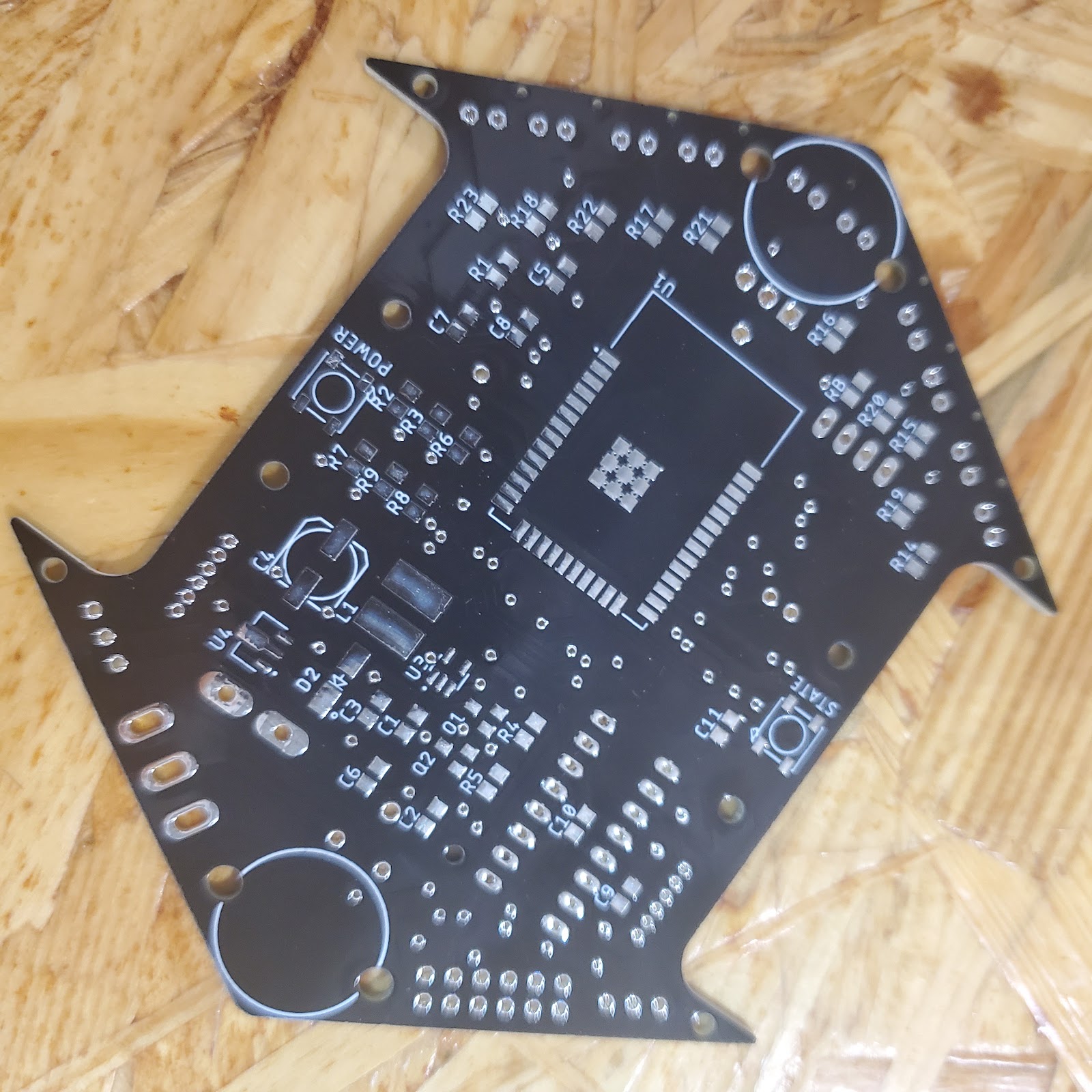 Figure 4. Bottom view of PCB v.1.0.2
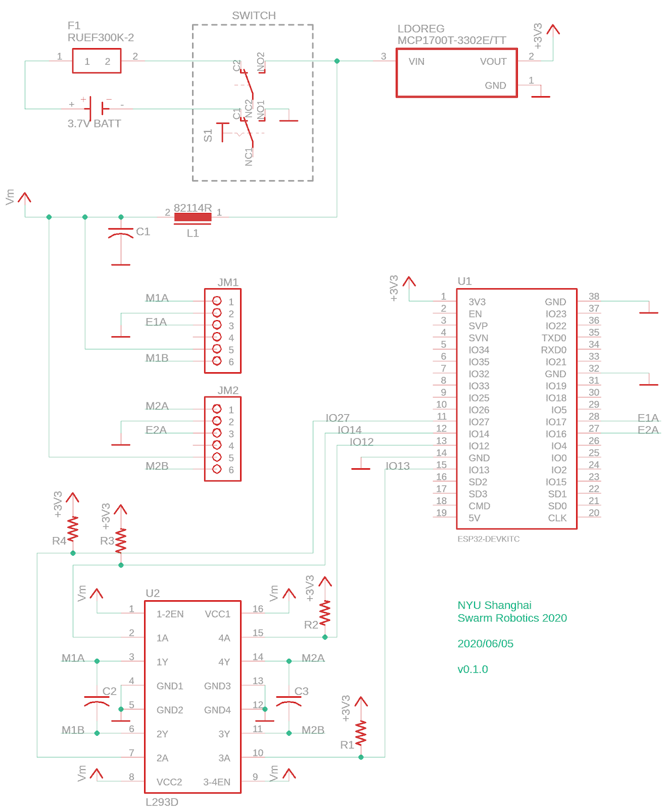
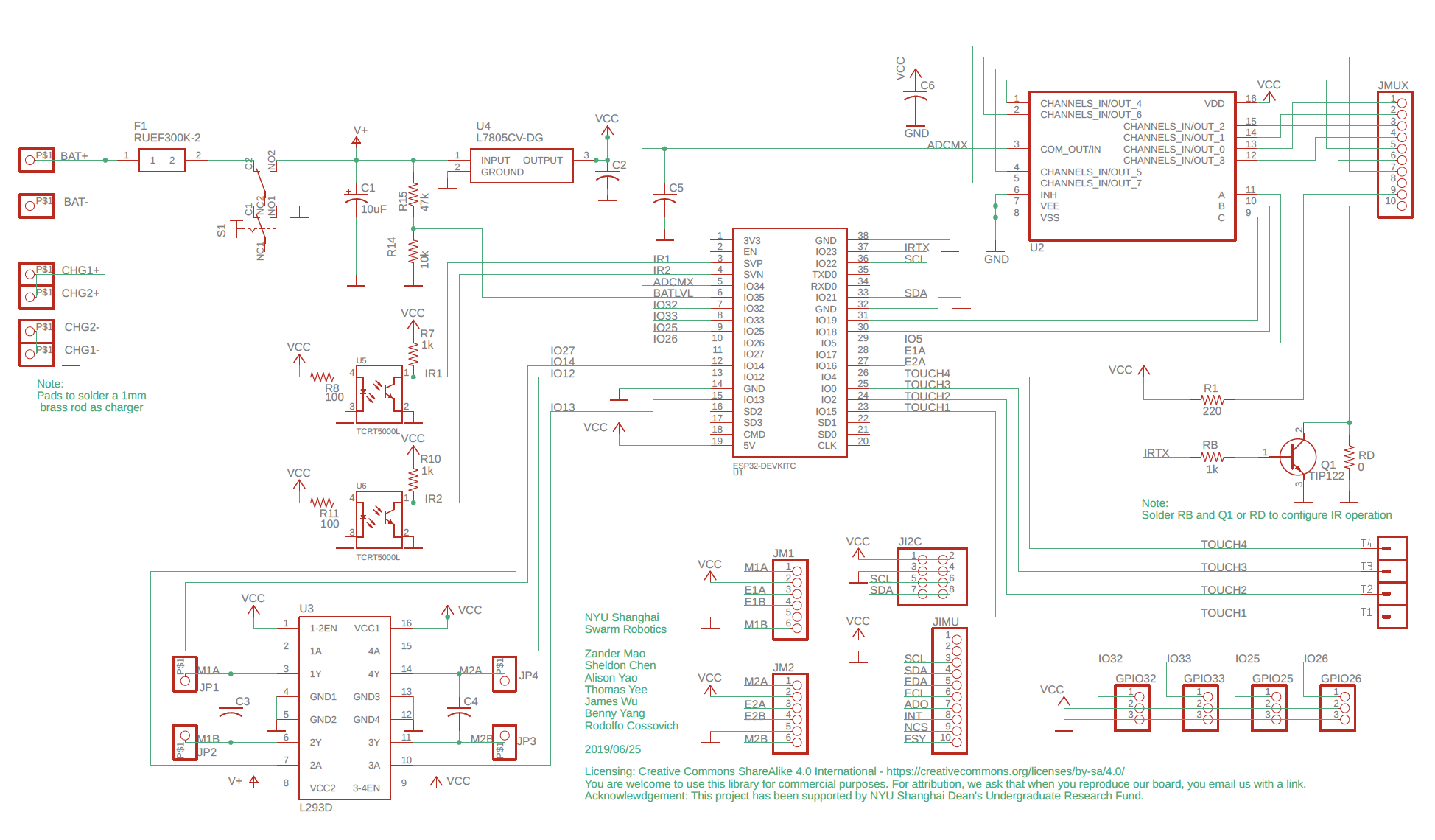
 Figure 5. Ai Thinker USB TO TTL Programmer


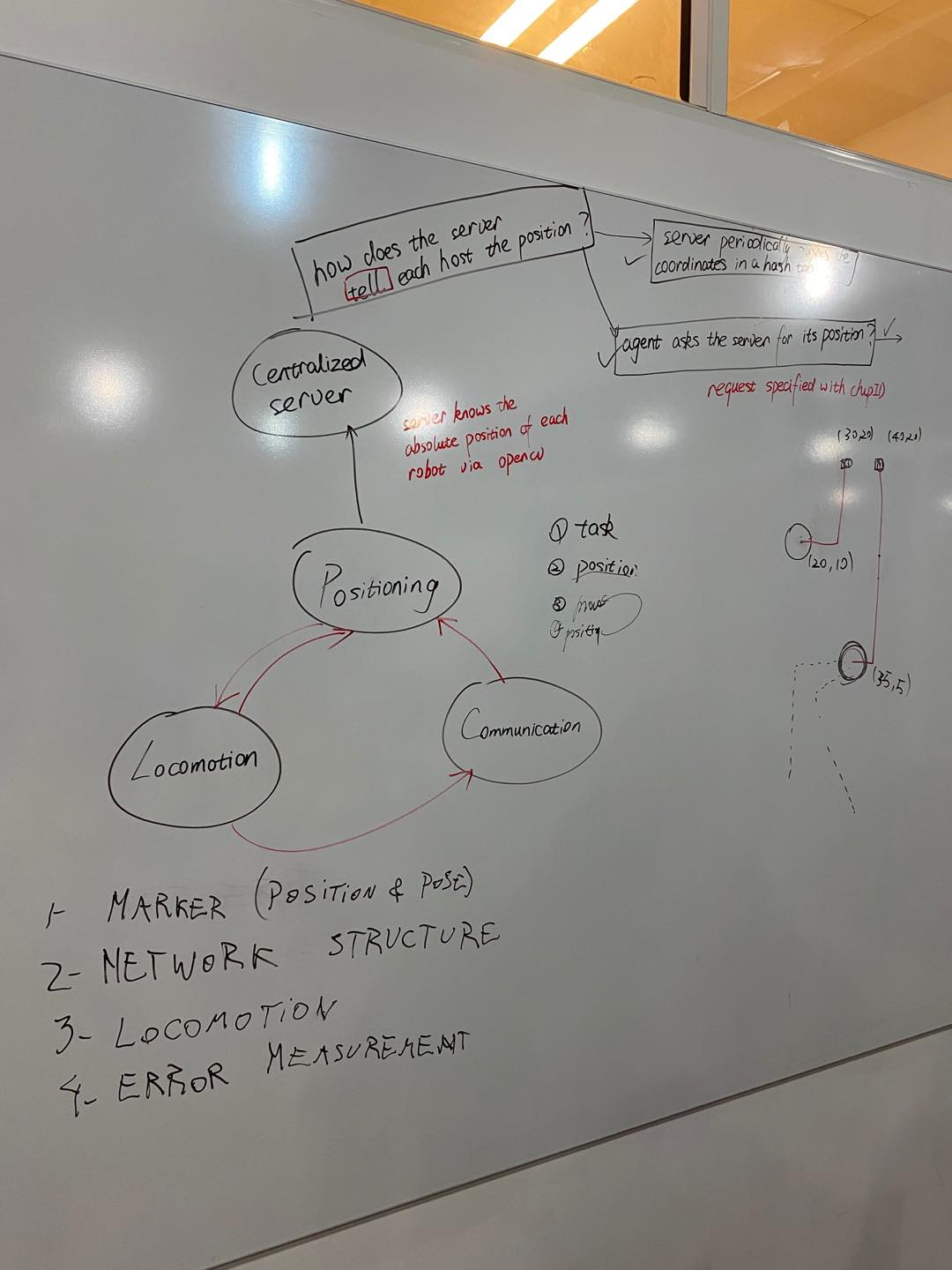
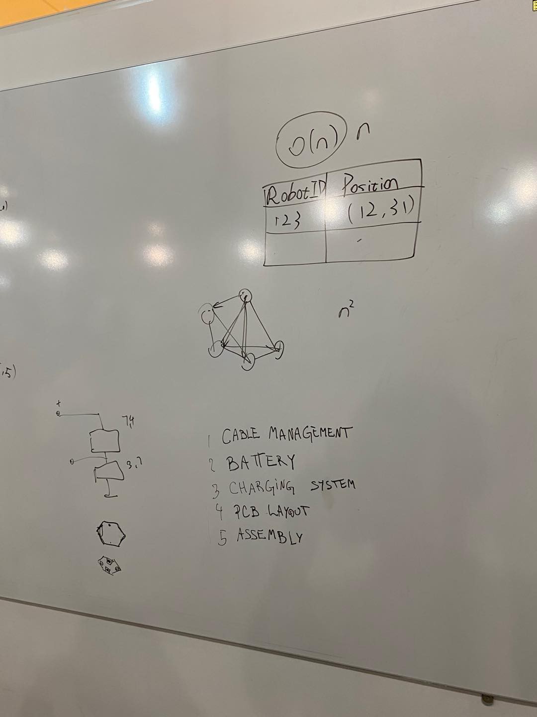

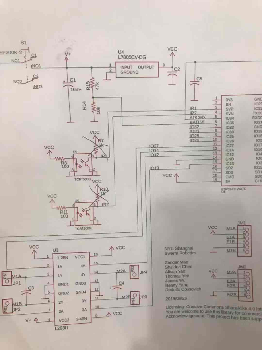
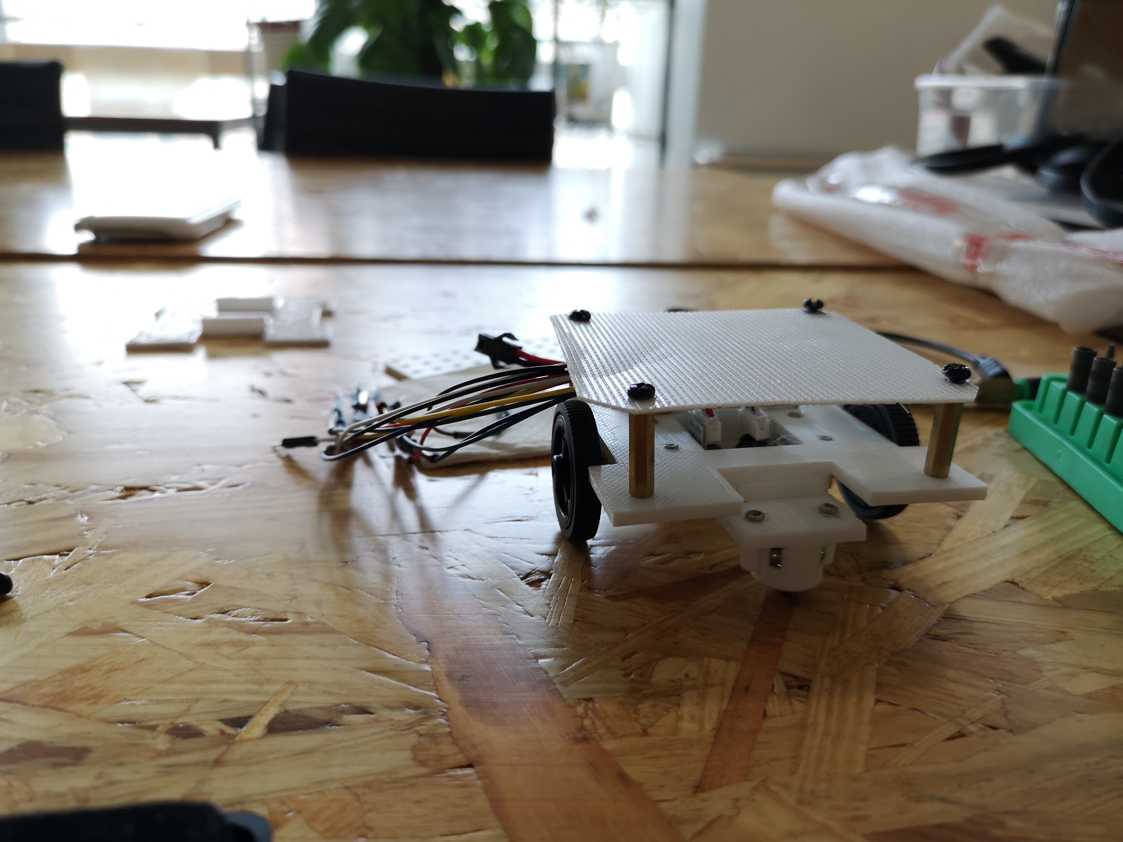
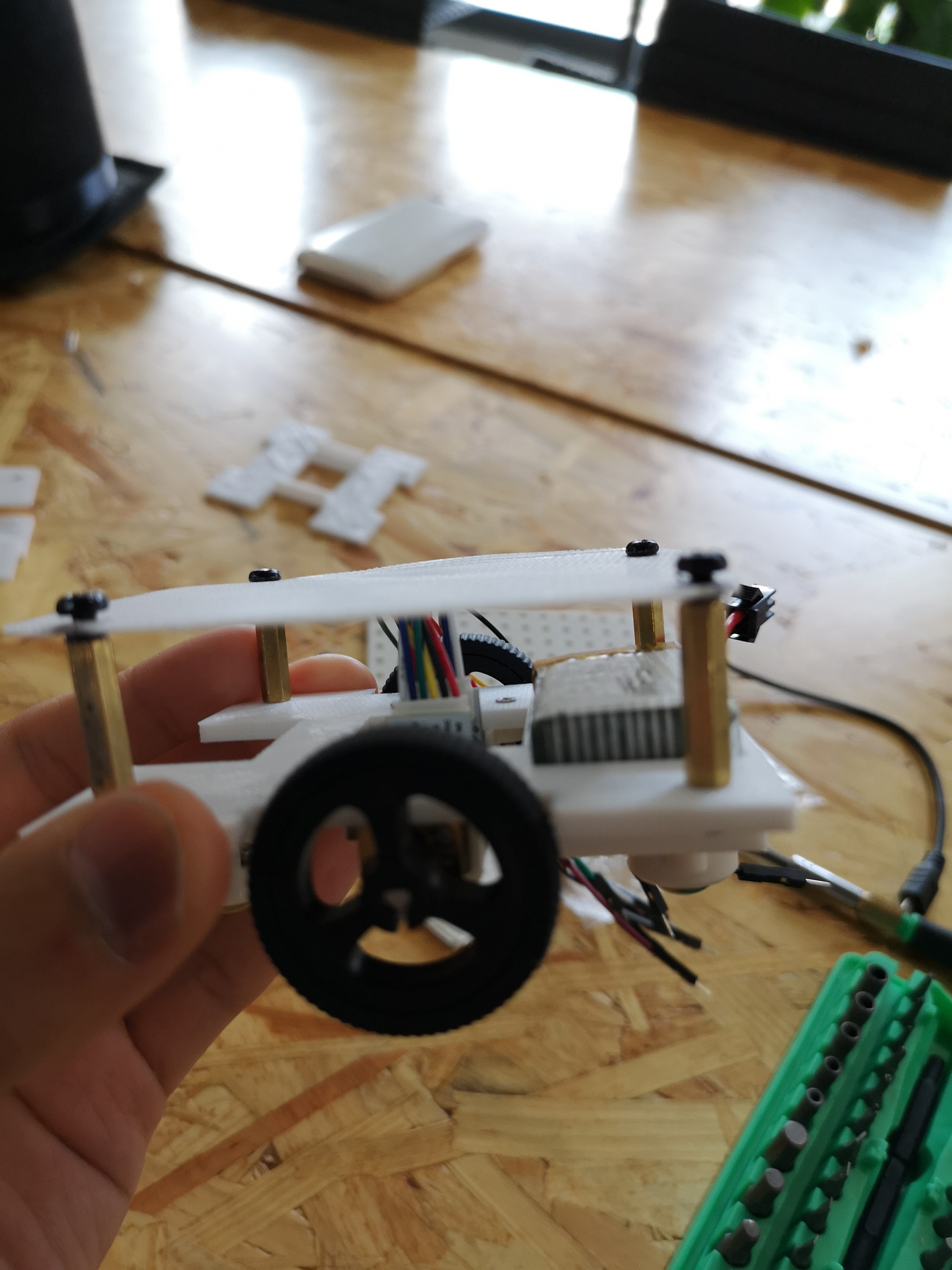
 When we were building the model, we took several things into consideration.
 Jack Qiao
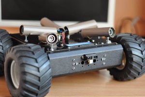
 Radu Motisan
 Keith Elliott
 maks.przybylski
I'm excited to see how this works out!!!