 mras2an
Logs section summary:
Functional diagram
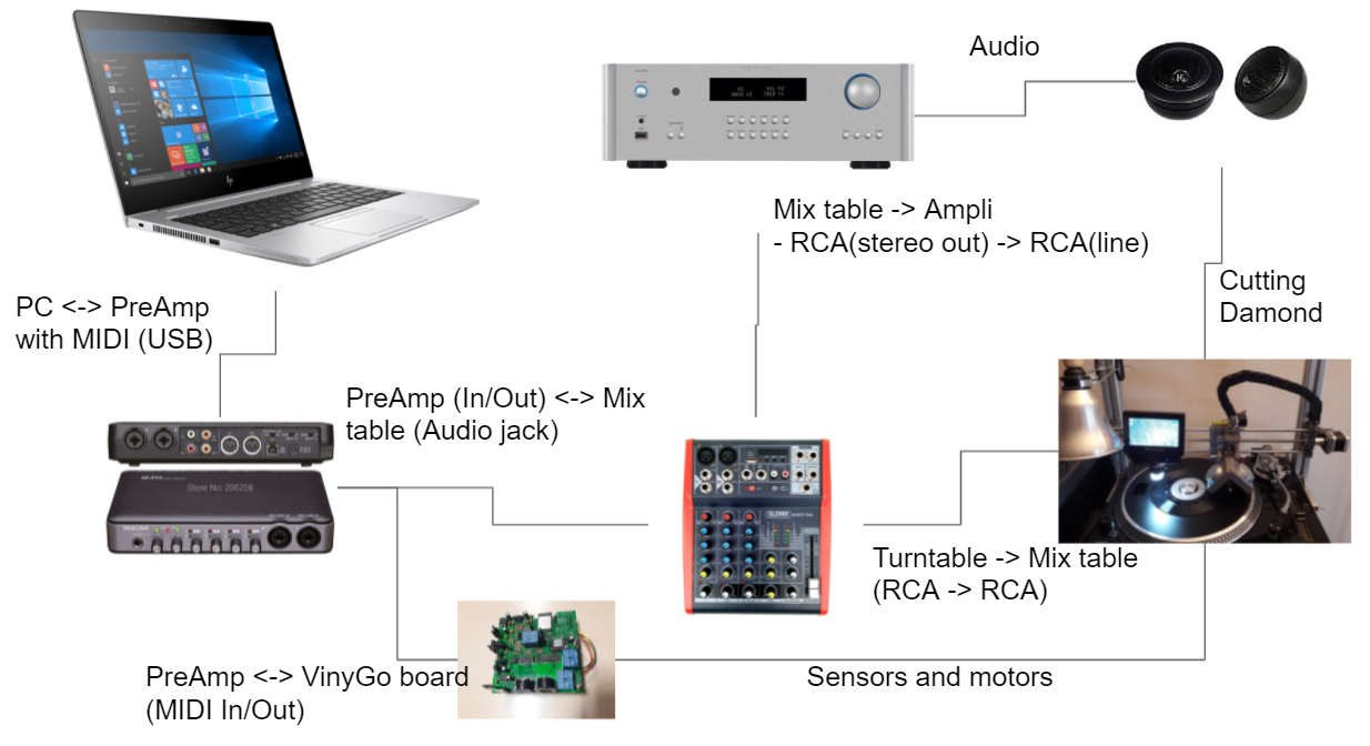
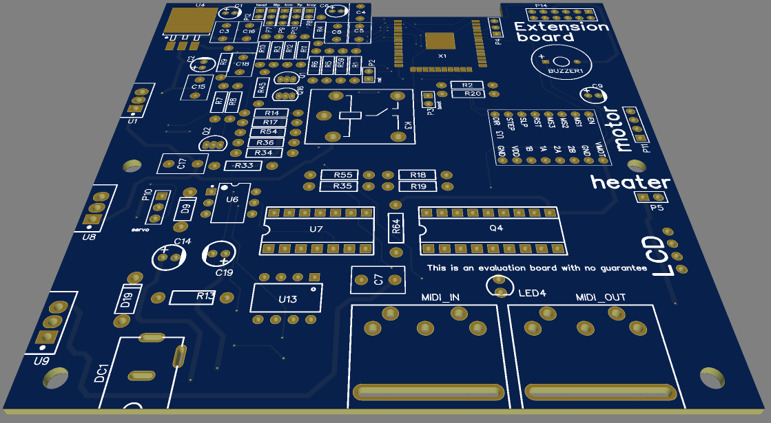
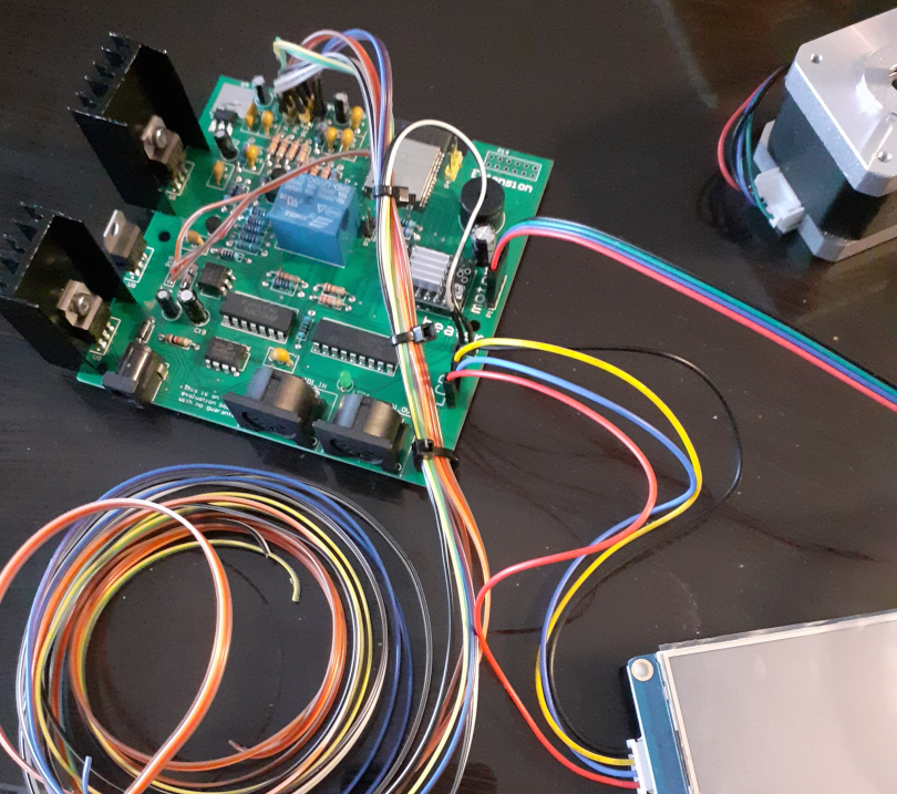
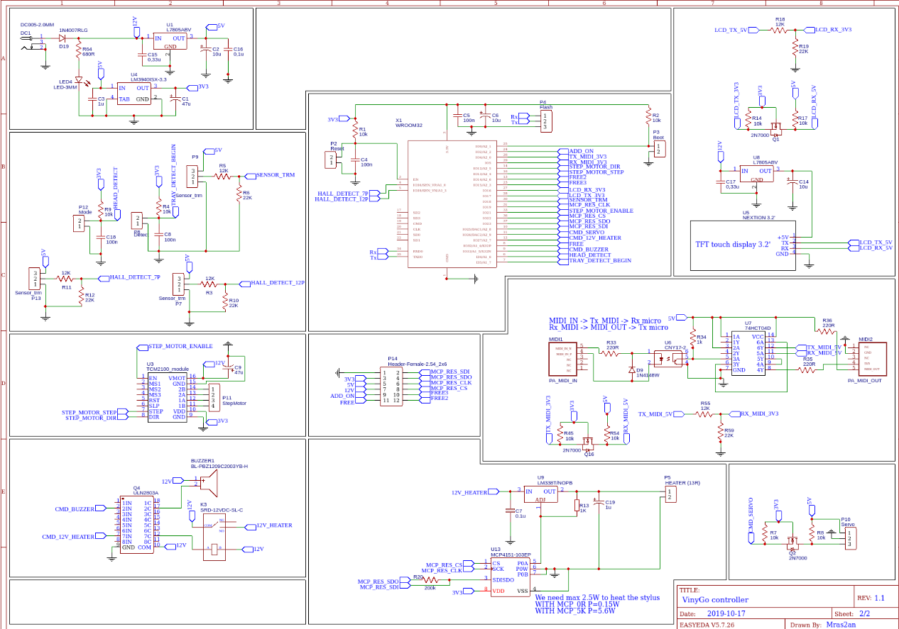
Electronic
The PCB
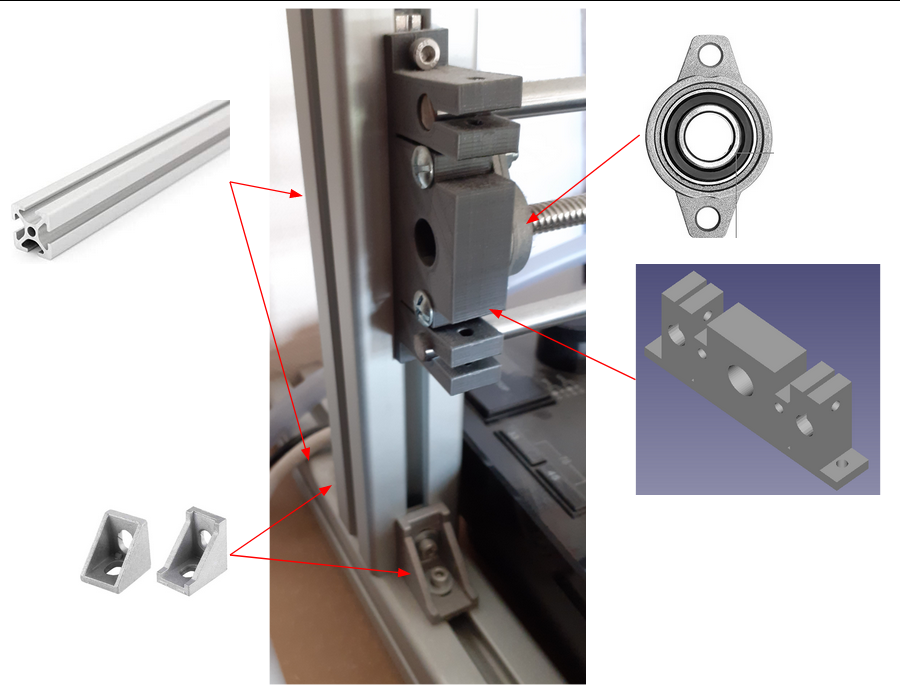
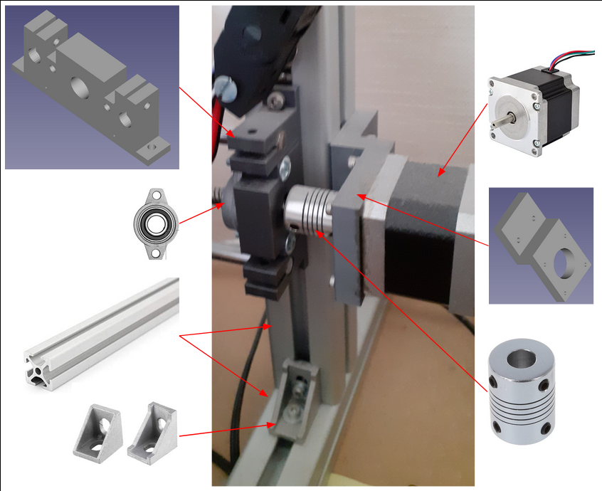
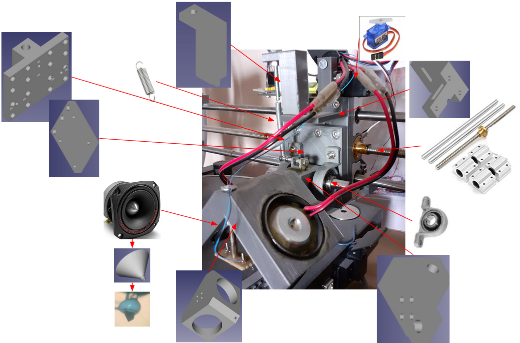
Mechanic V1
Mechanic V2
Software
Flash LCD Nextion
Flash and build ESP32
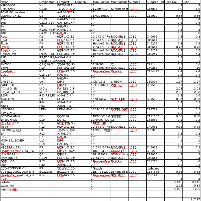
List and cost of components
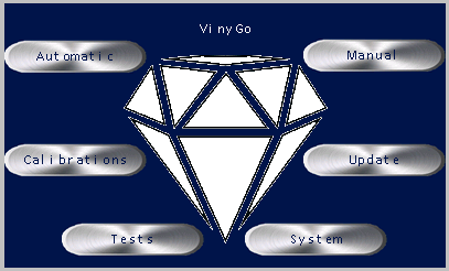
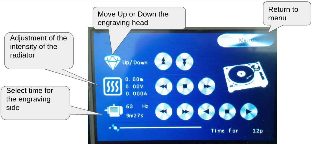
Getting started and functioning
1) Overview
1.1) Opportunity for vinyl recorders
Currently, vinyl disc industry facing to a shortage of polymers. This is due to the fire at the Apollo Masters factory and the covid-19 sanitary crisis. Order delays are very long and the prices have increased about 30% to 40% for industrial vinyl pressing. This leads to an almost impossible access to the small customer because the biggest customers are delivered before. It is therefore the small groups of music which have difficulty in making their own small series of vinyls. Vinyl recorders can solve this problem and make album creation accessible to small music bands (20 or 50 copies).
1.2) What vinyGo offers
Refresh old-fashioned vinyl technology by creating your own vinyls for:
- DJs: Preparing your mixes on vinyl before your party,
- Artists and music bands: Record your album on vinyl for you and your family,
- Vinyl stores and small recording studios: Offers a vinyl engraving service to your customers,
- Music lovers: Your favorite song does not exist on vinyl so create it.
1.3) How a vinyl recorder works
Burn sound on a matrix (vinyl)
It is the engraving of the audio signal by microgrooves on a matrix. Sound recording is in real time. A diamond, connected to two speakers (for stereo), vibrates above the blank lacquer which turns at 33 or 45 turns. The vibration is made by the speaker when the audio signal is played. This means that a groove is the exact representation of the speaker membrane vibration.
Mastering & Cutting
Before cutting the vinyl you have to apply some equalization like an iRIAA to the audio file. For the “cutting” you need to use a specific engraving diamond with an angle of 90 °.
1.4) Video
Note: The video sound is the sound of vinyl!
Sound extract "eye of the tiger" less than 20sec to respect copyright, and show the sound quality:
The proof:
2) Sagittal diagram
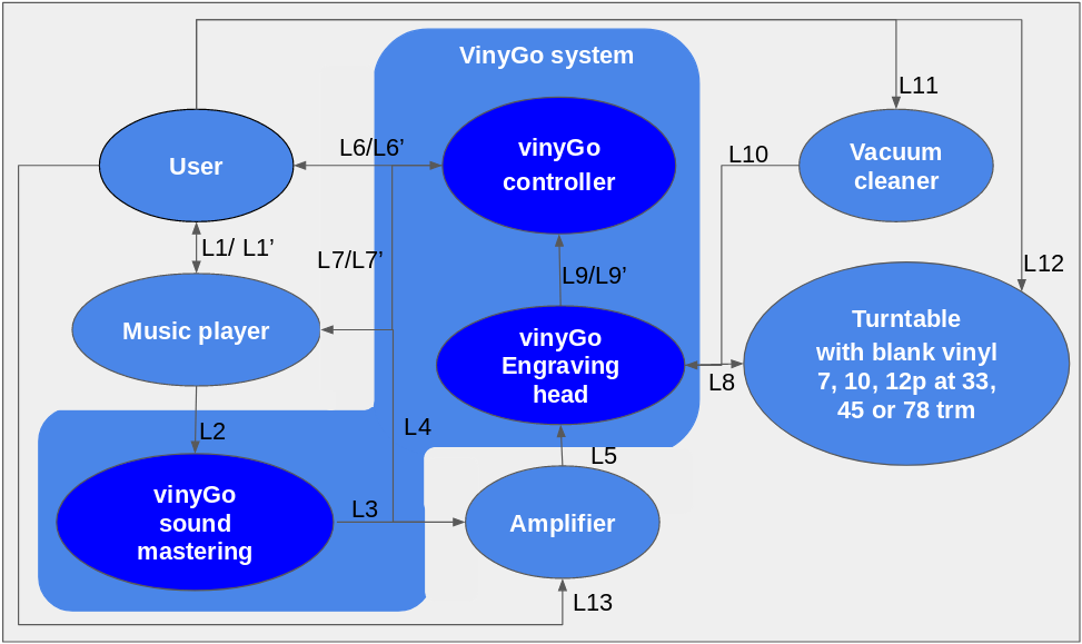
2.1) Description of the links
Note: VinyGo sound mastering can be done by software or by an extended board. Use L4 link if you use sound mastering by software or L2/L3 if you use a VinyGo sound mastering board. In this project presentation we use sound mastering software.
2.1.1) User
L1/L1’ :
- Select a playlist of music on your media player
- Configure the sound mastering
- Configure the MIDI commands of your media player for the start, middle, and end groove
L6/L6’ :
- Input/output to use the test mode
- Input/output to use the calibration mode
- Input/output to use the configuration mode
- Input/output to use the update mode
- Input/output to use the manual mode for the cutting vinyl
- Input/output to use the automatic mode for the cutting vinyl
L11 :
- Power on/off the vacuum cleaner
L12 :
- Turntable configuration (33, 45, 78TRM)
L13 :
- Adjust the sound volume
2.1.2) Media player
L1/L1’ :
- Inform the user of the playlist select
- Inform the user of the MIDI commands select
- Inform the configuration of the sound mastering
L2 :
- Useless (see note above)
L7/L7’ :
- Allows to send MIDI commands to the vinyGo controller to automatically change parameters (like speed motor).
L4 :
- Sound signal with mastering
2.1.3) ViniGo system
2.1.3.1) ViniGo controller
L6/L6’ :
- Inform the user of the current mode
- Inform the user of detected errors
- Depending on the mode, inform the user of the recorder time, position of the engraving head, diamond heating, state of the sensors, ...
L7/L7’ :
- Send MIDI commands to the media player
L9/L9’ :
- Get the information of the sensors
- Raising and lowering the head automatically
2.1.3.2) ViniGo sound mastering
L2 :
- Sound signal without mastering (useless, see note above)
L3 :
- Sound signal with mastering...


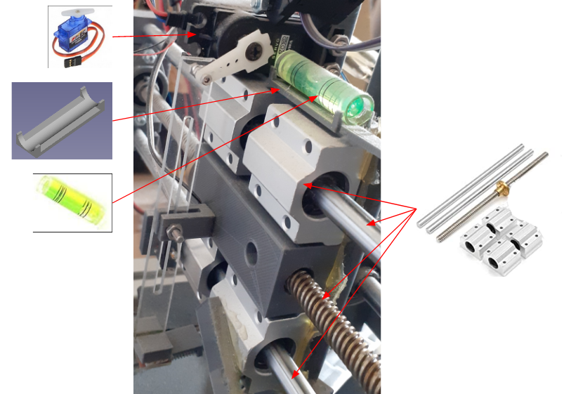
 6.2) Head

 Roland blade


 Clyne
Clyne
 mircemk
Hello I'm looking to buy a machine do you know where I can find a complete one?
Thank you Olivier